http://www.sciencepublishinggroup.com/j/ijecec doi: 10.11648/j.ijecec.20180402.11
ISSN: 2469-8040 (Print); ISSN: 2469-8059 (Online)
Liquid Cooled Technique for Solid State Power Amplifiers in
the Satellite Control Earth Stations
Olufunke Janet Alao
1, Olatunbosun Tafa Yusuf
2, *, Sikiru Yommy Aiyeola
3,
Mosunmola Bosede Sidiku
41
Department of Satellite Ground Control Station, Centre for Satellite Technology Development, Abuja, Nigeria
2
Department of Mechanical Engineering and Manufacturing, Centre for Satellite Technology Development, Abuja, Nigeria
3
Department of Space System, Centre for Satellite Technology Development, Abuja, Nigeria
4
Department of Engineering and Space System, National Space Research & Development Agency, Abuja, Nigeria
Email address:
*
Corresponding author
To cite this article:
Olufunke Janet Alao, Olatunbosun Tafa Yusuf, Sikiru Yommy Aiyeola, Mosunmola Bosede Sidiku. Liquid Cooled Technique for Solid State Power Amplifiers in The Satellite Control Earth Stations. International Journal of Electrical Components and Energy Conversion. Vol. 4, No. 2, 2018, pp. 72-77. doi: 10.11648/j.ijecec.20180402.11
Received: October 1, 2018; Accepted: October 25, 2018; Published: November 29, 2018
Abstract:
Solid State Power Amplifier (SSPAs) excessive thermal dissipation with high failure rate are becoming challenging tasks in the operation of satellite earth stations. Traditionally, forced-air cooled method has been the most well-known method adopted in removing excessive heat from high power SSPAs, but has not really prove so effective to bring down the heat to barest minimum. In this paper, we present the use of a liquid-cooled by developing a robust control system and heat exchanger module using temperature sensor, micro controller and water as coolant. Our design aims to optimize and increase the efficiency of the power amplifiers output and prevent failure or damage. The liquid-cooled thermal control module was built, assembled and tested within and outside the 35°C to 85°C operating temperature ranges of a typical SSPA. The result obtained shown that at the preset temperature of 35°C and below, the fan and pump were in the OFF state. At temperatures above 35°C, the fan and pump went into ON state simultaneously. In the event of fan or pump failure, (i.e. temperature above 85°C), the SSPA will automatically shuts down, the alarm will turn ON and the liquid crystal display (LCD) displayed fault. As the trend towards higher power dissipation and more concentrated heat sources continue in power amplifiers, a more effective solution is to use liquid cooled thermal control module to efficiently reduce heat dissipation in solid state power amplifier. It can be deduced from the overall results that aggressive heat dissipation removal in SSPAs is possible with liquid-cooled thermal control module.Keywords:
SSPA, Heat, Coolant, Forced-Air Cooled, Liquid-Cooled1. Introduction
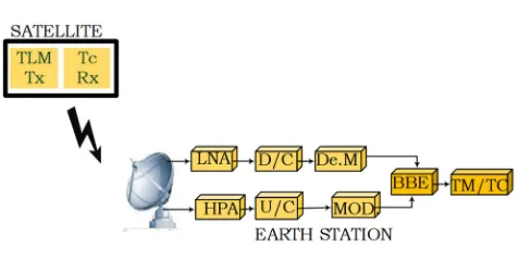
In radio frequency (RF) communication system, antenna is a vital component of an earth station [1]. Telemetries and tele-commands are sent to and received by transmitting and receiving radio waves using transmitters and receivers as shown in Figure.1.
Figure 1. Telemetry and Command.
onboard the spacecraft. It may have either a fixed or itinerant position depending on its designed mission. And also, pumps out RF energy, the electromagnetic channel that allows earth stations to communicate with satellite [2]. The baseband signal from the ground station require high RF power amplifier. Normally, the source signal must be amplified to achieve sufficient frequency and stability. In this modern development, request for high data and frequency have invaded the demands for sophisticated and more powerful power electronics than their predecessors and they communicate at higher frequencies.
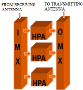
A typical example of high power amplifiers application in satellite and its ground station is depicted in Figure. 2, where it amplifies signals in each channel before the output multiplexer combine, amplified signals and send via the antenna.
Figure 2. Typical Structure of High Power Amplifier.
Figure 3. Power Amplifiers (RF) System.
A typical satellite earth-station’s transmitter includes the baseband signal from the earth station, the modulator to uplink frequency converter and the high-power amplifier as shown in Figure 3. and Figure 4. respectively [3]. The power amplifier's efficiency is a measure of its ability to convert the DC input power into the signal output power (Pout).
Pin = Pout + Pheat (1)
Where Pin is power input, Pout is the power output and Pheat is the heat generated.
Power amplifiers with low efficiency have high levels of heat dissipation, amplifiers output is always governing by temperature, if the temperature is beyond threshold, excess power dissipated, the amplifier gets damaged Thus, Amplifier efficiency (η) is the ratio of the power output (Pout) to the power input (Pin)
η = Pout /(PDC + Pin) (2)
Where, dissipated power Pdiss is
Pdiss = (1-η) PDC (3)
Amplifier Gain (G) in decibels is given by:
G =10 log (Pout/Pin) (4)
The output RF signal is directed towards the antenna feed and radiated
Figure 4. Earth Station Transmitter.
Antennas gain is realized by focusing power of the Effective Isotropic Radiated Power (EIRP). This may vary as a function of direction because of changes in the antenna gain and elevation. The transmitted power Pt of a transmitter at the antenna input is a function of the output power from HPA. The effective EIRP is a product of PtGt of the available power consider at the input of the antenna.
EIRP =10logPt + 10logGt (5)
Power lost before the antenna through the connectors Lcnt and RF interface Lint
Pt = (Pout) (1/Lcnt) (1/Lint) (6)
2. Power Amplifiers Thermal Effect
premature destruction of RF amplifiers.
Figure 5. Heat Dissipation in SSPA [5].
The manufacturers of electronic devices usually specify the rate of heat dissipation and power saturation level for reliable operation of HPA [5] as shown in Figure.6, which defined a 50W triquint HPA power output response at varying temperature. The temperature ranges from -40℃ to +85℃ temperature operating limit. The graph analysis indicates that the amplifier performs better at low temperature.
Figure 6. Solid State Power Amplifiers Performance [6]
3. Liquid Cooling Systems
Liquid cooling method is an electronics-controlled loop that recirculate a coolant at a preset temperature. An efficient cooling system is required to keep SSPA within its operating temperature limit. Ensuring the proper cooling of SSPA performance optimization and achieving a temperature compensation to extends MTBF, effective cooling system must be provided [6] to remove a large amount of heat flux from SSPA.
4. Methodology
The system design comprises of the cold plate and a thermal control unit. It includes a pump to circulate the coolant, a liquid heat exchanger for dissipation of heat to the environment, a microcontroller circuit to execute the cooling commands. The basic diagram for liquid cooling system is demonstrated in Figure 7. SSPA is fixed on the cooling plate with flow channels connected to the heat exchanger. The heat
exchanger extract heat and dissipate it to the environment [7]. A pump is configured to move coolant though the cold plate ad heat exchanger. The coolant continues recirculating and keep the temperature of SSPA within operation temperature.
Figure 7. Base Cooling Unit.
T = ∂Q/∂t (7)
Liquid cold-plate is the major component of the liquid-cooled module in which the heat from the source is removed by the moving fluid [8]. The use of cold plate in a closed loop liquid as shown in Figure 8, is to ensure that temperatures ranges are maintained. Liquid cooled plate design is based on the theory of heat transfer in which the temperature from the heat source is removed by conduction and cooled by convectional liquid flow. Considering the volume of the entire cooling system, the conductivity of the cooling plate is essential.
Figure 8. Cold plate model.
To increase the effectiveness of the cold plate and of the liquid cooling loop, recirculating coolant from the pump was used to chill the SSPA before it heads back to the reservoir and recirculated. The cold plate works base on heat transfer and oxidation principles [9]. Where ∂Q is the rate of heat flow from one side of an object, ∂t is heat transfers by conduction. Heat flow depends on the cross-sectional area of material used, the conductivity of the material and the temperature difference between the two objects.
Qcond = KA ((Thot -Tcold)/L) (8)
Where Q is the heat transfer rate in watts (W), K is the thermal conductivity of the material (WmK) and A is the cross-sectional area of heat path, ∂T/∂x is the temperature gradient in the direction of the flow (K/m). Therefore, the heat transfer rate by conduction through an object can be expressed as:
Q = KA(∂T/L) (9)
Where, L is the conductor thickness or length, ∂T is the temperature difference between one side and the other. The quantity ∂T/L in equation is called the temperature gradient and the quantity L/KA is the thermal resistance (R).
R= ∂/KA (°C) (10)
the thermal resistance depends on the nature of the material, thermal conductivity K and geometry of the body ∂⁄A. Heat transfer rate in conduction is:
Q = ∂t/R (11)
Thus, thermal resistance for conduction can be expressed as:
Rcond = ∂t/Q = L/KA = T/Pd = 1/h (12)
Where, conduction heat transfer coefficient is: h=K/l. If thickness of the cold plate increases with cross-sectional area, thermal conductivity increases, the thermal resistance decreases and heat transfer rate increases.
5. Liquid Cooled Thermal Control
Implementation
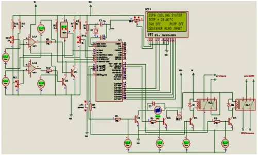
The basic design of the thermal control system includes a digital thermometer, microcontroller, pump and fan as shown in simulation circuit in Figure 9. A cooling fan 12VDC, microcontroller PIC 16F887A as the controlling brain of the cooling circuit. Temperature sensor LM35 allows for the measurement of SSPA temperature with output linearly proportional to temperature °C scale, its output changes by 10 mV per °C and It can operate over -55°C to 150°C temperature range. Equivalent output temperature is displayed using liquid crystal display (LCD). As shown in Figure 8. The circuit simulation was designed using Proteus-8 professional.
Figure 9. Simulated Circuit for Cooling System.
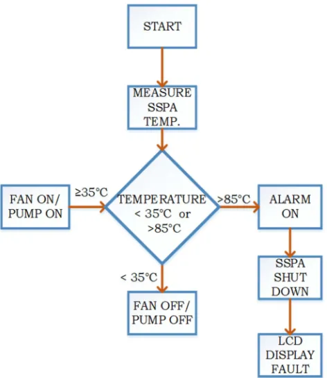
Initially, cooling system was powered up along with SSPA, voltage variation was applied by calibrating the corresponding voltage temperature. It was configured that SSPA has been powered and its temperature rises by varying input voltage. The cooling temperature was set to start cooling from 35°C to 85°C as depicted in Figure.10. The corresponding temperature
Figure 10. Cooling System Control Process.
6. Testing and Result
It has been coded that microcontroller should switch off fan and pump when SSPA temperature is operating within ambient temperature below 35°C. Temperature at 35°C and above, the microcontroller has been tasked to command the fan and pump to switch ON respectably [11], then LCD display “FAN ON and PUMP ON” The SSPA temperature continue cooling gradually at varying temperature with time. It was observed that device temperature was maintained within its designed temperature limit. The output temperature calibrations are tabulated in Table 1.
Table 1. Temperature output measurement.
S/N Thermometer (°C)
Output voltage (10mV/°C)
LCD output display (°C)
1 25 0.25 25.1
2 27 0.27 27.2
3 28 0.28 28..2
4 29 0.29 29.2
5 30 0.30 30.2
6 31 0.31 31.2
7 32 0.32 32.1
8 33 0.33 33.1
9 34 0.34 34.2
10 35 0.35 35.2
11 36 0.36 36.3
12 37 0.37 37.5
Test 1: SSPA Without Cooling System
The cooling system was disconnected from SSPA. It was observed that SSPA temperature continue to rise beyond its threshold range. The SSPA in operation without a cooling system or faulty cooling system is hazardous, hence, distort
the quality of transmitting signal at the receiver. Figure.11 shows the effect of uncontrolled temperature on SSPA as displayed on the graph. This effect triggered buzzer alarm to sensitise the earth station’s operator, LCD displayed, “FAULT” however, to prevent damage to the transmitting device SSPA is programmed to switch off autonomously.
Figure 11. Hot SSPA or Faulty Cooling System.
Test 2: SSPA with Cooling System
A thermal controlled cooling system is applied to SSPA to remove excess heat from the device. From design, cooling system has been programmed to switch ON and start cooling at 35°C and above, SSPA temperature is maintained within its varying operating temperature and gradually dropping as the coolant running in the closed loop system as shown in Figure 12.
Figure 12. A thermal controlled SSPA.
7. Conclusion
technique performed well under all conditions. The study concluded that aggressive heat dissipation removal in SSPA is possible with liquid-cooled thermal control module.
Acknowledgements
We thank the management of the Centre for Satellite Technology Development for their support and contributions toward the success of this work.
References
[1] Faisel EM M Tubbal, Akram Alkaseh and Asem Elarabi, “Telemetry, Tracking and Command Subsystem for LibyaSat-1, University of Wollongong Research Online,” 2015.
[2] Zhang Yinlong, “Satellite control center and china satellite telemetry, tracking and control network,” University of Wollongong Research Online Australia, 2018.
[3] Robert A. Nelson, “Earth station high power amplifiers KPA TWTA OR SSPA, Applied technology institute viasatellite,” 1998.
[4] Akhilesh Jain, P. R, Hannurkar, D. K. Sharma, A. K., Gupta, A. K., Tiwari, M. Lad, R. Kumar, P. D, Gupta and S. K, Pathak,
“Design and characterization of 50 kW solid-state RF amplifier, International journal of microwave and wireless technology, 2012.
[5] http://www.microwavejournal.com/articles/1181-a-compact-ef ficient-25-w-ku-band-power-amplifier/. Retrieved 2013. [6] Adriano da Silva Dias, Diogo Brum Cândido, Anand Placido
Almeida and Joable Andrade Alv, “Cooling methods design for power electronics converters. Juiz De Fora Brazil IEEE Xplore,” 2018.
[7] https://heatsinks.files.wordpress.com/2011/02/cooling-high-po wer-led.pdf/. Retrieved 2018.
[8] https://www.mouser.com/datasheet/2/412/TQP3M9019894309 .pdf/. Retrieved 2018.
[9] http://www.lytron.com/Cold-Plates/. Retrieved 2018.
[10] Jingyan Liu and Shunjing Guo, “Resistance furnace temperature control system based on PIC single chip, 8th International Symposium on Computational Intelligence and Design (ISCID, IEEE Xplore, Hangzhou, China,” 2016. [11] S. R Sharma, P. B. Dahikar, J. M. Pate and K. N.
![Figure 5. Heat Dissipation in SSPA [5].](https://thumb-us.123doks.com/thumbv2/123dok_us/967233.1596126/3.595.312.543.443.583/figure-heat-dissipation-in-sspa.webp)