MICROCONTROLLER BASED CONVERSION OF
SOLAR PV MODULE DC VOLTAGE TO AC USING
OCTOCOUPLER DRIVING THE GATE CURRENT
OF 3 PHASE INVERTER
Devesh U. Sarkar
1and Harshit S. Dalvi
2I.INTRODUCTION
Photovoltaic Module, through photoelectric experience, produce electricity in a nonstop electricity generation way. PV panels are completely silent, noise is not come on producing; as a result, they are a wonderful solution for city areas and for housing applications. Because of that solar power coincides within energy needs for cooling PV Modules can offer an useful solution to power demand peaks – specially in hot summer months where power insist is Peak.
A core of Processor, I/O programmable peripherals & Memory this are includes in a Microcontrollers. NOR flash is a Program Memory which is also frequently built-in on chip, as well as a characteristically tiny amount of RAM. Microcontrollers are designed for embedded applications, in dissimilarity to the microprocessors used in personal computers.
Microcontroller with Solar PV creates a vital role, Programming which is help to make pulses for Inverter means MOSFET, it is considered as a unipolar device and I n this implementation of experimental work uses N-Channel MOSFET because it gets electrons which is having high Mobility.
1
Department of Electrical Engineering G H Raisoni College of Engineering, Nagpur, Maharashtra, India
2
Department of Electrical Engineering G H Raisoni College of Engineering, Nagpur, Maharashtra, India
DOI: http://dx.doi.org/10.21172/1.82.050
e-ISSN:2278-621X
Abstract- In this paper the total work is done experimentally in which Solar PV DC Voltage has been converted into AC. In this Proposed work Microcontroller Plays a very vital role as 3 Phase Inverter needs to be given pulses and for this we have used a 725mA 1ϕ Transformer and the Transformer output which is AC is Converted in DC and this DC is given to the Series Voltage Regulator LM7805 and then the output of this Voltage Regulator is Fed to Microcontroller. Now, the Microcontroller Output is given to TLP250, which is an Octocoupler which drives the Gate Current of 3ϕ Inverter and Pulses is given to the 3 Phase Inverter. Now connect the Solar PV Module to Input of Inverter in which gets Output of 3 Phase Inverter in 120° mode & the Phase Voltage obtained is in the form of Quasi Square Wave.
II. NECESSARYCOMPONENTSOFPROPOSEDWORK
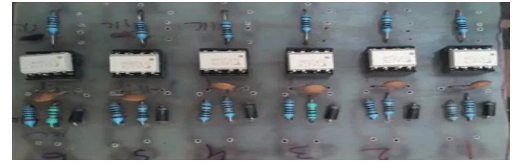
A. Transformers–
Picture1: There are 5 Transformer one is for microcontroller and remaining 4 is for TLP250
According to the Proposed work here uses five Transformer having capacity of 725mA×1, 500mA×4. Transformer is a device which static by nature because of no rotating in it. So it is only work to transform Power from one circuit to another. In this case, 725mA is giving to Microcontroller for +5V supply and 500mA is applied for giving the supply to TLP250 Octocoupler.
B. Microcontroller AT89C52
Picture2: AT89C52 μC which is mounted on a PCB
This is a low-power and having High-performance CMOS 8-bit microcontroller with 8K bytes of Flash programmable and erasable read one memory (PEROM). Atmel’s high-density nonvolatile memory technology is a technology which is used to construct this device and is compatible with the industry-standard 80C51 and 80C52 instruction set and pin out. The program memory to be reprogrammed in a system for that having permission from On-chip Flash, so the On-chip allows it.
C. MOSFET
Picture3: This one is the 14A, 500V, 0.4Ω, N-Channel Power MOSFET
D. TLP250 Octocoupler
Picture4: This is a photocoupler consist of light emitting diode and photo-transistor
This is a one type of Photocoupler consist of LED and a integrated photo detector. DIP is a package which is having 8 lead this is unit of TLP250. TLP250 is suitable for gate driving circuit of power MOSFET. Supply current is 11m ampere, output current is ±5A, Switching time is 1.5μs and also having Isolation voltage is 2500Vrms.
E. Series Voltage Regulators
The LM78XX series of three terminal regulators is available with several fixed output voltages making them useful in a wide range of applications. The local on card regulation from among the series voltage Regulator which deletes the problem by distribution which is associated with the help of Regulation of Single Point. In Hardware implementation uses two type of series Voltage Regulators viz. LM7805 & 06.
III. METHODOLOGY
A. Hardware Explanation by using Circuit Diagram
[a]Microcontroller Designing
Fig. 1 Designing of Microcontroller AT89C52
For every Microcontroller whether it is AT89C51, AT89C52, whether it is AT89C20. For all the cases we need some standard condition, star connection at least power supply section which has been separately discuss where have a step down transformer and then gets 12V AC. 12V AC passes through a bridge rectifier and bridge rectifier gives pulsating DC. Pulsating DC is further filter, so getting a 12V DC here and 12V DC is passes through Voltage Regulator LM7805 and gets +5V DC supply here.
If it is to be operated directly from the battery then there is do not need to do supply as the Microcontroller needs +5V DC. Take 6V Battery and connected diode in series with solve the purpose of supplying +5V to the microcontroller 40 pins, 20 no. pin is always in negative(GND).
P 0.0/A D0
P 0.6/A D6 P 0.5/A D5 P 0.4/A D4 P 0.3/A D3 P 0.2/A D2 P 0.1/A D1
P 0.7/A D7 P 2.0/A 8 P 2.2/A 10 P 2.1/A 9
P 2.7/A 15 P 2.6/A 14 P 2.5/A 13 P 2.4/A 12 P 2.3/A 11
P 3.0/RXD
P 3.6/WR P 3.5/T 1 P 3.4/T 0 P 3.3/INT 1 P 3.2/INT 0 P 3.1/T XD
P 3.7/RD P 1.0 P 1.6 P 1.5 P 1.4 P 1.3 P 1.2 P 1.1 P 1.7 AT 89C52 E A A LE P S EN
RS T X T AL2 X T AL1 7 8 0 5
V I V O
V CC GND TRANSFORMER 230V AC BRIDGE RECTIFIER 1000 UF 12V 12V 33PF 0V 0.1UF
7 8 0 5
V I V O
+5V to TLP250 Input 12MHz CRYSTAL OCCILATOR 33PF 10K ohm 10UF 1 9 1 8 9 3 0 2 9 3 1 1 8 7 6 5 4 3 2 3 2 3 4 3 5 3 3 3 6 3 7 3 8 3 9 2 8 2 6 2 5 2 7 2 4 2 3 2 2 2 1 1 6 1 4 1 5 1 7 1 3 1 2 1 1 1 0
2 0 4 0
The other connections are very standard where crystal which is connected at pin 19 & 18 and there is a 33pf capacitor 2 no. which are connected to the grounds. The RESET pin is necessary, to use the RESET pin with a capacitor which is connected to the positive terminal, the electrolytic capacitor positive terminal & negative terminal is goes to the RESET pin and negative terminal through a resistor is going to the Ground.
This circuit having a switch and call it a RESET switch & the functions are when the supply is switch on, that means whether through battery or through supply. When the supply is switch on, that capacitor from the positive supply starts conducting or charging so this point goes high initially.
After some times the charging current through the capacitor will stop because the charging will take place. The charging current will stop, once the charging current stop, then this point will remains at ground potential because this is in ground potential. So initially at the time of switch ON this point goes high after that is goes to ground that is negative, that is necessary for the program that is written here to starts from the beginning otherwise the program may starts from half. To ensure that the program starts from beginning this arrangement has been made, the RESET arrangement which is a very standard connection for all the microcontroller. Pin no. 31 is to be held that means it is connected to positive that is for the purpose if wish to program it while it is in the circuit then this particular pin use. Since programming it when it is externally when we take it out programming it bring it as per the manufacturer data sheet is required to be connected to positive point so pin 31 is connected to positive point so this are the standard connection.
B. Microcontroller C-Programming
#include<reg51.h>
#include<intrins.h>
#include <stdio.h>
Void delay (int);
Char counter=0;
Unsigned char pulse1,pulse2,pulse3;
unsigned char
pwm[10]={0x01,0x02,0x03,0x04,0x05,0x04,0x03,0x02,0x01,0x01};
bit toggle=0;
sbit r=P2^0; // 21
sbit y=P2^1; // 22
sbit b=P2^2; // 23
sbit ri1=P2^3; // 24
sbit yi1=P2^4; // 25
sbit bi1=P2^5; // 26
Unsigned char volt, pr [10];
Void it_timer0 (void) interrupt 1 using 1 {
TH0=0xD5;
TL0=0x37;
Toggle=! toggle;
if(toggle==1){r=1;y=1;b=1;ri1=1;yi1=1;bi1=1;}
if(toggle==0) {
Counter++;
if(counter>=7)
counter=1;
if(counter==1){
r=0;y=0;b=1;b=pwm[pulse1];_nop_();_nop_();ri1=1;ri1=pwm[pulse1];yi1=1;
yi1=pwm[pulse1];bi1=0;}
if(counter==2){
r=1;r=pwm[pulse1];y=0;b=1;b=pwm[pulse1];_nop_();_nop_();ri1=0;yi1=1;yi
1=pwm[pulse1];bi1=0;}
if(counter==3){
if(counter==4){
r=1;r=pwm[pulse1];y=1;y=pwm[pulse1];b=0;_nop_();_nop_();ri1=0;yi1=0;bi
1=1;bi1=pwm[pulse1]; }
if(counter==5){
r=0;y=1;y=pwm[pulse1];b=0;_nop_();_nop_();ri1=1;ri1=pwm[pulse1];yi1=0;
bi1=1;bi1=pwm[pulse1];}
if(counter==6){
r=0;y=1;y=pwm[pulse1];b=1;b=pwm[pulse1];_nop_();_nop_();ri1=1;ri1=pwm[
pulse1];yi1=0;bi1=0;} }}
void main(void){
TMOD=0x20;//IE=0x82;IE=0x82;TR0=1;TH0=0xDB;TL0=0x37;
while(1); }
void delay(int d){
int i;
for(i=0;i<d;i++)
}}
C. Structure of System Designing with Microcontroller’s +5V DC input
A C1 B1 A1 C B R Y B
-+
SOLAR PV MODULE INPUT F 7815 VI VO TRANSFORMER BRIDGE RECTIFIER 1000 UF 15V 0V 0.1UF 0.1UF 5 5 7 6 3 8 2 +15V +5VKPin no. 21
1k ohm To MOSFET A 1k ohm 7815 VI VO TRANSFORMER BRIDGE RECTIFIER 1000 UF 15V 0V 0.1UF 0.1UF 5 5 7 6 3 8 2 +15V +5VK
Pin no. 22
1k ohm To MOSFET B 1k ohm 7815 VI VO TRANSFORMER BRIDGE RECTIFIER 1000 UF 15V 0V 0.1UF VO 0.1UF 5 5 7 6 3 8 2 +15V +5VK
Pin no. 23
1k ohm To MOSFET C 1k ohm 7815 VI VO TRANSFORMER BRIDGE RECTIFIER 1000 UF 15V 0V 0.1UF VO 0.1UF 5 5 7 6 3 8 2 +15V +5VK
Pin no. 24
1k ohm To MOSFET A1 1k ohm 5 5 7 6 3 8 2 +5VK 1k ohm To MOSFET B1
1k ohm 5
5 7 6 3 8 2 +5VK 1k ohm To MOSFET C1 1k ohm
Fig. 2 Proposed work Methodology Fig. 3 3ϕ Inverter Methodology
Methodology: In this proposed work the Solar PV DC Voltage is converted into AC by 3ϕ Inverter but the 3ϕ Inverter wants the pulses that is giving by TLP 250 which is an Octocoupler and its work is to drive the gate current of MOSFET. Proposed Hardware having 5 Transformer among them one is going to giving supply to Microcontroller and remaining 4 is giving supply to TLP250 circuit.
When the supply from 725mA step down Transformer step down capacity is 12V DC then by LM7805 regulator its convert it in +5V DC and this supply is going to the input of Microcontroller AT89C52 and another LM7805 regulator is giving to the TLP250 input for supply due to this inside on TLP250 LED is on and the photo transistor is on off. After that one 500mA×4 15V step down Transformer is giving the supply to 4 power supply capacitor. After that among 4 power supply capacitor , three power supply capacitor which is passes through LM7815 and gets 15V DC at pin no. 8, and pin no.5 is ground and all 6 TLP250 getting +5V supply from LM7805 which is situated at Microcontroller and giving the symbol ‘K’ to pin no.2 applied to all 6 TLP250. Microcontrollers pin. no.
21,22,23,24,25,26 is going to all 6 TLP250 at pin no.2 by 1KΩ resistor.
Among 5 transformers, one is for microcontroller, three is for three TLP250 and one Transformer is for three TLP250 because that remaining three TLP250 is common terminals for MOSFET.
Three TLP250’s pin no. 6 and 7 is goes to A, B, & C of Power MOSFET with 1KΩ resistor and the remaining Three TLP250’s pin no. which is a common because its pin no. 5 & 8 is gets common so only one transformer is sufficient to supply this remaining Three TLP250 and its output means pin no. 6& 7 is goes to the Common of MOSFET A’,B’ & C’.
So the Now that 4 Transformers for 4 Capacitor which is sufficient to giving supply to 6 TLP250 and now by LM7815 +15V DC output is having on TLP250 and TLP250 is capable to giving pulses to 3ϕ Inverter. Finally, Solar PV module is giving input to 3ϕ Inverter and 3ϕ 120° mode output gets.
IV. TESTINGOFHARDWAREWITHRESULTS
A. Testing of Solar PV Module
B. Testing of Microcontroller & TLP250
Picture6: Check the inputs of Microcontroller and TLP250
[a] Result( Check Microcontroller’sInput
Picture7: Getting Appropriate +5V DC Input from Power Supply
[b] Result(Pulses of TLP250)
Picture8: Getting appropriate input pulses of 15V DC from TLP250 to 3ϕ Inverter
C. Ouput of 3ϕ Inverter when giving DC input from Solar PV Module
[a] Result(Input of Solar PV Module during Testing time)
Picture9: Getting 13.8V DC input of Solar PV Module during Testing Time
Picture10: Getting 15.4V AC output at 3ϕ 120° mode operation of Inverter. Output is a quasi square waveform because here is calculating phase Voltage
D. Overall Synchronised Hardware System
Picture11: Total Hardware of the system design
V. CONCLUSION
When solar PV Module or Battery giving DC supply of 13.8V DC to 3ϕ Inverters input then 3ϕ Inverter makes it in AC form in 120° mode and giving output of 15.4V AC which is Quasi square waveform because inverter is operated at 120° mode Operation, these is because inverter is SPWM in which Microcontroller Role is very Important, it is because TLP250 is giving pulses only due to microcontroller’s input. Solar PV Module is getting 13.8V DC during testing time. Microcontroller AT89C52 gets +5V DC input from 725mA Transformer by using Rectifier and voltage Regulator.
REFERENCES
[1] Ariya Sangwongwanich, Yongheng Yang, and Frede Blaabjerg, “High-Performance Constant Power Generation in Grid-Connected PV Systems,” IEEE TRANSACTIONS ON POWER ELECTRONICS, VOL. 31, NO. 3, MARCH 2016, pp.1822-1825
[2] Behnam Tamimi, Claudio Cañizares, and Kankar Bhattacharya, “System Stability Impact of Large-Scale and Distributed Solar Photovoltaic Generation: The Case of Ontario, Canada,” IEEE TRANSACTIONS ON SUSTAINABLE ENERGY, VOL. 4, NO. 3, JULY 2013, pp.680-688
[3] Rupesh G. Wandhare, Vivek Agarwal, “Reactive Power Capacity Enhancement of a PV-Grid System to Increase PV Penetration Level in Smart Grid Scenario,” IEEE TRANSACTIONS ON SMART GRID, VOL. 5, NO. 4, JULY 2014, pp.1845-1853
[4] Marco Liserre, Remus Teodorescu, Frede Blaabjerg, “Stability of Photovoltaic and Wind Turbine Grid-Connected Inverters for a Large Set of Grid Impedance Values,” IEEE TRANSACTIONS ON POWER ELECTRONICS, VOL. 21, NO. 1, JANUARY 2006, pp.263-272
[6] Rupesh G. Wandhare, and Vivek Agarwal, “Novel Stability Enhancing Control Strategy for Centralized PV-Grid Systems for Smart Grid Applications,” IEEE transactions on Smart Grid, vol. 5, no. 3, May 2014, pp.1389-1396
[7] Habbati Bellia, Ramdani Youcef, Moulay Fatima, “A Detailed modelling of photovoltaic module using MATLAB,” NRIAG Journal of Astronomy and Geophysics, May 2014, pp. 53-61
[8] S.V. Swarna Kumary, V.Arangarajan Aman Maung Than Oo, GM Shafiullah, Alex Stojcevski, “Modeling and Power quality analysis of a Grid connected Solar PV System,” Australasian Universities Power Engineering Conference, AUPEC 2014, Curtin University, Perth, Australia, 28 September – 1 October 2014, pp. 1-6
[9] Chinmay Jain, Bhim Singh, “Solar Energy Used for Grid Connection: A Detailed Assessment Including Frequency Response and Algorithm Comparisons for an Energy Conversion System” IEEE Industry Applications Society, Volume: 23 Issue: 2, December 2016, pp.37-50
[10] G. Deepak, M. Jaya Bharata Reddy, D. K. Mohanta, “Hardware implementation of grid connected PV system with energy management scheme” IEEE, Environment and Electrical Engineering (EEEIC), February 2014
[11] Mohamed Amine Fakhfakh, Moez Ayadi, Rafik Neji, “Implementation of photovoltaic system into microcontroller” IEEE, Renewable Energies and Vehicular Technology (REVET), May 2012
[12] Neha Adhikari, Bhim Singh, A. L. Vyas, Ambrish Chandra, Kamal-Al-Haddad, “Analysis and design of isolated solar-PV energy generating system” IEEE, Industry Applications Society Annual Meeting (IAS), November 2011, PP. 1-6