e-ISSN: 2278-7461, p-ISSN: 2319-6491
Volume 6, Issue 10 [October. 2017] PP: 10-17
Line Follower Robot for Industrial Manufacturing Process
Abhijit Pathak
1,
Refat Khan Pathan
2,
Amaz Uddin Tutul
3,
Nishat Tahsin Tousi
4,
Afsari Sultana Rubaba
5,
Nahida Yeasmin Bithi
61, 2, 3, 4, 5, 6, Department of Computer Science and Engineering, BGC Trust University Bangladesh, Chittagong.
Corresponding Author: Abhijit Pathak
Abstract:
Line follower robot is one kind of autonomous robot which follows a line until that line exists. Generally, the lineis drawn on the floor. It can be either black or white. The line can also be normal visible color or invisible magnetic field or electric field. The robot follows the line by using Infra-Red Ray (IR) sensors. There are five IR sensors which makes it an IR sensor array. These sensors read the line and send that reading to Arduino and then control the robot movement. In this paper, the authors will explain about the robot design, implementation, coding, testing, problems they faced and their solutions.
Keywords
: Line Follower, Arduino Uno R3, Adafruit Motor shield, IR sensor array,DC Power Adapter (9V,2A)
--- --- Date of Submission: 25-09-2017 Date of acceptance: 10-10-2017 --- ---
I.
INTRODUCTION
Line follower robot is autonomous that means it automatically follows a line which is pre-defined. Generally, it follows a black line on a white surface or a white line on a black surface. Some of the basic operation of a line follower is given below:
Reading the pre-defined line by IR sensor array which is installed on the front-down side of the robot and sends those reading to the Arduino. The ATMega microcontroller which is built in on Arduino analyzes those reading and do the particular operations.
The steering mechanism is simple in this robot. Three wheels are used, two wheels are on the back part connected with the motors and one independent wheel on the front-middle part of the robot.
On Straight line, the speed is fast and on a turn, speed is relatively slow depending on turn angel. Good motor quality and good sensing quality will increase the robot movement performance.
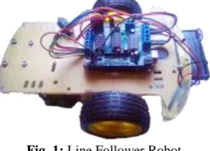
Fig. 1: Line Follower Robot
DC motors Chassis board
Power supply (9V/12V DC)
The IR sensor reads the line and sends the analog reading to the Arduino through the analog pin on Arduino Uno board (A0-A4 pin).On white line analog reading is less than 300 and on black line analog reading is greater than 600. The minimum analog reading is 0 and maximum is 1023 (10 bit binary). That reading distinguishes between black and white colors by which robot senses the line.
Arduino board and other devices get power supply through EXT_PWR pin on Adafruit motor shield by 9V DC battery. If 12V DC battery is used, then a 12V to 9V DC power supply converter also will have to use for device’s safety.
1.1
Digital IR sensor Array
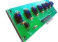
The line follower robot uses 7 array digital IR sensor array to sense the line. Among them, five IR sensors are used because there are six analog pins on Arduino. For balancing left and right side four sensors are used and one middle sensor for line detection. On each IR sensor, there are two diodes. One of them send Infra-red rays and another one receives it. If the receiver receives more reflected light than it is on the white surface and if receives less reflected light (or doesn't receive any reflected light) that means it is on the black surface. One IR sensor includes one infrared transmitter and one receiver. IR sensor array is the combination of five IR reflectance-sensors.
Fig. 2: IR Reflectance Sensor Array
The distance between the surface and the IR sensors array should be less than 5mm and distance between two IR sensors depends on line width. The sensors work well if it is shielded from ambient light.
The IR sensor array has been set up on the bottom side of the chassis. Those sensors are giving analog reading to Arduino depends on the IR ray reflectance. For accuracy left two sensors reading average and right two sensors reading average will decide the movement of the robot. A sample program is given below:
Fig. 3: Sample follower paths
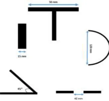
Fig. 4: Angle Detection methods for Sensor
According to the Fig: 4, the width of the line is 15mm. When it will find "T" shape surface, the robot will stop. The top length of the applied "T" shape is 50mm as the IR reflectance sensor's width. This is able to move 120mm diameter of the curve in a circle. It will be forwarded to the break point between two lines is 40mm. If the break point of two lines is larger than 40 mm, it may loss the path.
1.2
Arduino Uno R3
Arduino Uno R3 is a microcontroller board based on the ATmega328P (datasheet). It has 14 digital input/output pins (of which 6 can be used as PWM outputs), 6 analog inputs, a 16 MHz quartz crystal, a USB connection, a power jack, an ICSP header and a reset button. It contains everything needed to support the microcontroller; by simply connecting it to a computer with a USB cable one can program it. It supports 5V DC to 12V DC. The safe power supply is 9V DC. Arduino controls the whole robot actions. The motor shield is placed above it. Motor shield's pins are connected to Arduino's pins.
Fig. 5: Arduino Uno R3
1.3
Adafruit Motor Shield
Authors have chosen the Adafruit motor shield because it suits well with Arduino. Moreover, it has some more quality with classification. There is four connection point for four motors. As authors used two motors, so among four points two points M1 and M2 are used.
The motor shield also has six analog pins (A0-A5). The IR sensors are connected to Arduino through this analog pins (A0-A4). Motor speed is controlled through this motor shield. It allows the motor to spin both clockwise and anti-clockwise. From the EXT_PWR point, external power supply is given by battery.
Arduino send instructions to motor shield and it controls the motors cause's four states. a. Both motors are on and rotating forward causes forward movement.
b. Right motor is rotating forward and left motor is rotating backward causes a Right turn. c. Left motor is rotating forward and the Right motor is rotating backward causes Left turn. d. Both motors are off causes stop point of the robot.
Fig. 7: Adafruit Motor Shield
1.4
Motors and Wheels
Motors are very important part of this robot. Because the movement system is the main part of the line following. Some most important things are that both motors must be the same kind, speed, power supply and smooth. So choosing motors are very important as there are so many kinds of motors available in markets. Here the authors have used 4V DC gear motors. Wheels also have to be same size and radius. Wheel size effects on the robot speed.
Authors are using three wheels. Among them, two are connected back side of the chassis with motors and one wheel is independent and connected to the front side of the chassis.
1.5
Body and the Chassis
Robot body is another important thing. One can use many kinds of chassis but it should be kept in mind that chassis has to support all devices and also has to be strong. It can be made from glass, plastic, aluminum or any other lightweight materials.
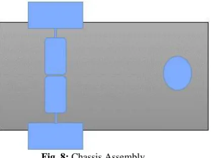
Fig. 8: Chassis Assembly
III.
ASSEMBLY AND PIN CONNECTION
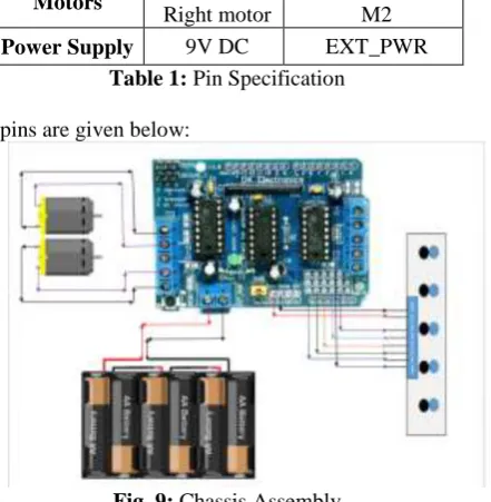
The motor shield is placed above the Arduino connecting Arduino with motor shield. The IR sensor array gets 5V DC power supply from the motor shield's 5V pin, and sensors GND pin is connected to motor shield's GND pin. Sensors pins are added to shield's analog A0-A4 pins. External power supply is given through EXT_PWR pin.
Device Pins Motor Shield
Pins
IR sensor
5V GND
IR1 IR2 IR3 IR4 IR5 SEN
5V GND
A0 A1 A2 A3 A4 D2
Motors Left motor
Right motor
M1 M2
Power Supply 9V DC EXT_PWR
Table 1: Pin Specification
Chassis assembly according to pins are given below:
Fig. 9: Chassis Assembly
IV.
SOURCE CODE
Arduino microcontroller has its own IDE for coding. It supports C as a programming language. Arduino IDE has its own facility to connect Arduino to computer via USB cable and passes enough current and code through it.
As the authors used Adafruit motor shield, there is a library for that motor shield. This library supports motor control functions. The main functional process is given below:
#include <AFMotor.h> //Adafruit Motor Shield Library
AF_DCMotor motor1(1, MOTOR12_8KHZ ); //create motor #1 using M1 output on Motor Drive Shield, set to 8kHz PWM frequency
pinMode(A3,INPUT); pinMode(A4,INPUT); analogWrite(2,255); }
int sp=85; // setting motor speed void loop()
{
int l,r,t=100; //300 is the value that distinguish between black and white
int left; int right; int middle; l=analogRead(A0)+analogRead(A1); r=analogRead(A3)+analogRead(A4); middle=analogRead(A2); left=l/2; right=r/2;
if(left<t && right<t) //move forward { motor1.setSpeed(sp); motor2.setSpeed(sp); motor1.run(FORWARD); motor2.run(FORWARD); l=analogRead(A0)+analogRead(A1); r=analogRead(A3)+analogRead(A4); left=l/2; right=r/2; }
else if(left<t && right>t) //turn right {
while(left<t && right>t) { motor1.setSpeed(sp); motor2.setSpeed(sp); motor1.run(BACKWARD); motor2.run(FORWARD); l=analogRead(A0)+analogRead(A1); r=analogRead(A3)+analogRead(A4); left=l/2; right=r/2; } }
else if(left>t && right<t) //turn left {
while(left>t && right<t) { motor1.setSpeed(sp); motor2.setSpeed(sp); motor1.run(FORWARD); motor2.run(BACKWARD); l=analogRead(A0)+analogRead(A1); r=analogRead(A3)+analogRead(A4); left=l/2;
right=r/2; }}
else if(left>t && right>t && middle>t) //stop {
while(left>t && right>t && middle>t) {
motor2.run(RELEASE); }
} }
V.
LINE FOLLOWER PATHS
Line follower robot follows path drawn on the floor. The line will be mainly black on a white surface. If it occurs any line break on its way, the robot will go forward. If it finds a cross line, the robot will stop. Lines and robot movements can be changed by using programming code easily. Some lines are that the robot can follow:
Fig. 10: Sample path
The robot will follow a bad angle of 45° and cycle or bad curves. It will stop when it finds a cross black line.
Fig. 11: Polygon shape Path
On any kind of Polygon, it can follow the line and maintain a particular speed.
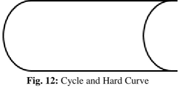
Fig. 12: Cycle and Hard Curve
The line may have cycles and unwanted curves that it has to follow on narrow space or moving one room to another.
VI.
FUTURE WORK
VII.
CONCLUSION
Robotics has a significant role in global economy and everyday life. Another concern of robotics research is to be competitive and design patents for global industries according to their nature of applications. The demand of robotics technology is expanding in wide range of applications and human activities, especially for manufacturing, medical, service, defense, and consumer industries. The Designed robot has five IR sensors, Arduino microcontroller board, and Adafruit motor shield. Arduino mainly controls the robot to follow the line. This line follower robot is the prototype of robots for industrial use. By studying this one can build line follower robot for industrial use. Performance can be improved by using good materials and great sensing power also improves motor movement. The setup cost of line follower robot majorly depends upon the expensive machinery, land, and building and round the clock staff to maintain and use that machinery. In Bangladesh where the population is humongous and resources are scarce.
So, it becomes really difficult to set up such a capital extensive project without any financial supports from private sectors. Skilled staffs are also necessary for that. This is alternate to the existing system by replacing skilled labor with robotic machinery. This robot will be able to handle more goods in a manufacturing process in less time with better accuracy as well as lower per capital cost.
ACKNOWLEDGEMENT
The authors would like to thank Syed Minhaz Hossain for valuable discussion and gratefully acknowledge the facilities of the department of CSE, BGC Trust University Bangladesh.
REFERENCES
[1] https://playground.arduino.cc/Main/AdafruitMotorShield
[2] http://www.buildtronix.com/arduino-uno-evelopment-board-with-atmega328.html
[3] International Journal of Advanced Research in Computer Engineering & Technology (IJARCET) Volume 2, Issue 8, August 2013 ISSN: 2278 – 1323
[4] https://www.slideshare.net/rehnazrazvi/line-following-robot-16014541
[5] Miller Peter, “Building a Two Wheeled Balancing Robot”, University of Southern Queensland, Faculty of Engineering and Surveying. Retrieved Nov 18, 2008.
[6] Datasheets of microcontroller AT89C51, LDR sensor, IR proximity sensor, Motor driver L293D, Comparator, 16*2 LCD, Available: http://www.alldatasheet.com
[7] M. Zafri Baharuddin, Izham Z. Abidin, S. Sulaiman Kaja Mohideen, Yap Keem Siah, Jeffrey Tan Too Chuan,"Analysis of Line Sensor Configuration for the Advanced Line Follower Robot",University Tenaga Nasional.
[8] http://www.roboticsbible.com/simple-line-following-robot.html
[9] Nor Maniha Abdul Ghani, Faradila Naim, Tan Piow Yon, “Two Wheels Balancing Robot with Line Following Capability,” World Academy of Science, Engineering and Technology, pp-634-638, 2011. [10] Author:-Jacob Millman, Christos Halkias, Chetan D Parikh, Publisher-McGraw Hill, Comparator
Page(s)-647
[11] http://www.electrosome.com/line-follower-robot-without-microcontroller/
[12] E-ISBN 974-1-4244-5586-7.Authors:-Pakdaman, M; Sanaatiyan, M.M.; Ghahroudi, M.R.
[13] https://www.researchgate.net/publication/224132741_A_line_follower_robot_from_design_to_implement ation_Technical_issues_and_problems
[14] Cao Quoc Huy, "Line Follower Robot", University UPG din Ploiesti.
[15] P. Heyrati, A. Aghagani, "Science of Robot Disgn and Build Robot" in , Azarakhsh Publication, 2008. [16] https://learn.adafruit.com/adafruit-motor-shield/library-install
.