e-ISSN: 2278-7461, p-ISSN: 2319-6491
Volume 5, Issue 2 [November 2015] PP: 15-19
Reactive Power Compensation Using Various Flexible AC
Transmission System Devices
Shilpa S. Shrawane
1, Dr. Manoj B.Daigavane
2 1GHRCE, Electrical Department, Research Scholar, Nagpur ,India2GHRIETW,Principal,Nagpur, India
Abstract:
The Reactive Power Compensation (RPC) plays a vital role in decreasing the power loss of transmission lines and reducing the voltage deviation. The system load keeps on changing continuously and so results into system parameters changes. Tap changing transformers, capacitor banks and synchronous condensers were conventionally used for the compensation. Flexible AC Transmission System (FACTS) devices are found to be more efficient in this regard. In this paper modeling of Thyristor Controlled Series Capacitor (TCSC) as one of the FACTS devices is considered for solving the RPC problem.Keyword
: FACTS, TCSC, reactive power control, lossI.
INTRODUCTION
The Reactive Power Compensation (RPC) is very important for keeping the voltage profile constant at all the buses in power system for secure and economic operation of power systems. The reactive power generation by itself has no cost but however it affects the total generation cost by decreasing the transmission loss. By the reactive power compensation the transmission loss will be minimized because RPC mainly deals with power factor improvement. So, its consequence is to lower the production cost by satisfying the constraints. Environmental, cost problem are major hurdles for power transmission network expansion. Pattern of generation that results in heavy flows tends to incur greater losses and reducing the stability and security of the power system[1,2].
The increasing Industrialization, urbanization of life style has lead to increasing dependency on the electrical energy, resulted into rapid growth of power systems which resulted into few uncertainties. Power disruptions and individual power outages are one of the major problems and affect the economy of any country. In contrast to the rapid changes in technologies and the power required by these technologies, transmission systems are being pushed to operate closer to their stability limits and at the same time reaching their thermal limits due to the fact that the delivery of power have been increasing. [4,9]The major problems faced by power industries in establishing the match between supply and demand is:
1. Transmission & Distribution; supply the electric demand without exceeding the thermal limit.
2. In large power system, stability problems causing power disruptions and black-outs leading to huge losses. These constraints affect the quality of power delivered. [2,3] However, these constraints can be suppressed by enhancing the power system control. One of the best methods for reducing these constraints is FACTS devices. Recently with the advent in power electronics technology , many FACTS devices have been evolved Hence there is an interest in better utilization of available capacity by installing Flexible AC Transmission System (FACTS) devices such as Thyristor Controlled Series Capacitor (TCSC), Thyristor Controlled Phase Angel Regulator (TCPAR) , Unified Power Flow Controller (UPFC), Static Synchronous Compensator(STATCOM) and SVC help in controlling the flow in heavily loaded lines and enhance system power flow efficiency.
These new devices are more efficient in controlling present transmission and distribution systems of electricity . In this study, Power flow mathematical modeling of TCPAR and UPFC is done for reactive power compensation using MATLAB /SIMULINK environment .
II.
MATHEMATICAL MODELLING OF VARIOUS FACTS DEVICES
(1) where
Similarly the active and reactive power from bus j to bus i is given by
]
(2)
2.1 Thyristor Controlled Phase Angle Regulator (TCPAR)
The voltage angles between the buses i and j could be regulated by TCPAR. The block diagram model of TCPAR with transmission line is shown in Fig 1.
Fig.1 .TCPAR model
[1]The injected real and reactive power injected in buses i and j are :
(3)
(4)
where
2.2
Unified Power Flow Controller (UPFC)
UPFC can be considered as a combination of series connected voltage source for series compensation and shunt connected voltage source for shunt compensation. The inserted voltage has a maximum magnitude of Vt=0.1Vm, Where Vm is the rated voltage of the line, where the UPFC is connected. A series inserted voltage and phase angle of series inserted voltage source which affects UPFC performance when inserted in the network can be modeled as follows.. The block diagram model of UPFC with transmission line is shown in Fig 2.
Fig.2 UPFC model
The real and reactive power injected at buses i and j are:
(5)
(6)
III.
SIMULATION RESULTS AND DISCUSSION
The simulink model for the uncompensated system is shown in Fig. 3. The simulation results of system for real and reactive power flow for uncompensated lines depicts that the real power flow though the line is 0.9417MW and the reactive power is 0.462MW. The result are shown in Fig. 4
Fig. 3 Simulink model for uncompensated transmission line
Fig. 4 Real and Reactive power flow without compensation
The power supplied to the load when FCTCR is considered as a compensation device can be regulated using two factors
1. The magnitude of shunt capacitance C
2. The delay angle of the thyristor controlled reactor.
The firing angle of the FCTCR is varied keeping the value of capacitance constant and vice versa. The effect of varying the parameters of FCTCR on the real and reactive power flow through the line for the insertion of FCTCR can be observed from the results tabulated in Table 1.
The waveform for the real and reactive power supplied to the load is as shown in Fig. 5.
Table 1 Simulation results of real and reactive power flows for insertion of FCTCR by varying its different parameters
S.No. FCTCR with α=60° and C variable FCTCR with C = 250µF and α variable
Capacitance (µF)
P (MW)
Q (MVAR)
Firing angle (α)
P (MW)
Q (MVAR)
Fig. 5 Real and Reactive power flow with FCTCR
Similarly ,the power flow through line using UPFC can be regulated by two factors 1. Series Injected voltage
2. Shunt current source
By controlling the magnitudes of the series injected voltage source and that current magnitude of the shunt current source, the power flow through the line can be regulated .Here for the analysis one parameter is varied at a time keeping the other constant. Therefore when the magnitude of the voltage source is varied, current source magnitude is kept constant and vice versa.
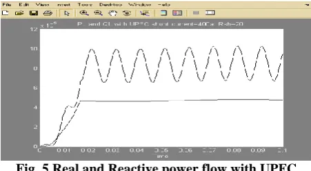
The waveform for the real and reactive power supplied to the load is as shown in Fig. 5.
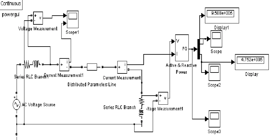
Table 2 indicate the results of using UPFC. Here the value of the shunt current source magnitude, resistance of the shunt current source, magnitude of series voltage source , its phase angle are the parameters based on which the power flow can be regulated . Here for analysis, the simulations are carried out for variation in one of the parameter at a time keeping other constant . The results are depicted in the Table 2 indicate the variation in the real and reactive power for different values of shunt current source and series voltage source of UPFC respectively and the waveforms of the complex power supplied to the load have been found and are as shown in Fig. 6.
Fig. 5 Real and Reactive power flow with UPFC
Table 2 Simulation results of real and reactive power flows for insertion of UPFC by varying different parameters
S.No. Rsh=500Ω ,
Ish= 100A V
and varying φser of Vser =1100V
Ish=300∠0° ,
Vser=0 V
and varying Rsh
Rsh=500Ω ,
Vser= 0 V
and varying Ish
phase angle of Vser in degree
P (MW)
Q (MVAR)
R
sh
in Ω P (MW)
Q (MVAR)
Shunt current source in A
P (MW)
Q (MVAR)
1 0 1.144 0.5717 20 0.9452 0.4752 50 0.9424 0.4711 2 90 0.9818 0.4779 50 0.9492 0.4758 100 0.9442 0.4719 3 120 0.963 0.4826 100 0.9489 0.476 200 0.9469 0.4736 4 180 0.8203 0.3995 200 0.9487 0.468 300 0.9511 0.4741 5 210 0.794 0.3842 500 0.9485 0.452 500 0.9588 0.4801
The simulation is performed on the uncompensated line and the real and the reactive power flow through the transmission line are measured. It can be concluded from the results that , the Real and reactive power flow through the transmission line changes with the insertion of FACTS controllers in the line .Various parameters of these FACTS devices are varied and the results are tabulated. From the simulation results obtained using SIMULINK ,it is observed that real and reactive power supplied to the load is improved by using FCTCR and UPFC as compared to the line without any compensation device. This satisfies the purpose of ORPD which is nothing but to decrease the power loss through transmission and improving the power flow through the line.
REFERENCES
[1]. S.M. Sadeghzadeh, A. H. Khazali, S. Zare; “Optimal reactive power Dispatch considering TCPAR and UPFC”,IEEE 2009,pp577-583
[2]. Dommel, H. W. and Tinney , W. F., Optimal power flow solutions. IEEE Transactions on Power Apparatus and Systems, 1968, 87, 1866–1876
[3]. K . Satyanarayana, B.V. K.Prasad, et al; “Optimal location of TCSC with minimum Installation Cost using PSO”,IJCST,Vol.2,2011,pp 156-160
[4]. C. A. Canizeres,M. Porse; “STATCOM Modelling for Voltage and Angle Stability Studies”, Electrical Power and energy systems 2003,pp1-20
[5]. A. S. Bawankar and V. P. Rajderkar ;”Thyristor Controlled Series Compensator to Resolve Congestion Caused Problems”,IJEE,2009,pp-11-14
[6]. S. Hadjeri,Fatiha G.and et al;“Simulation of a three –level 48 –pulse STATCOM ”, ACTA ELECTROTECHNICA , 2008,pp 189-194
[7]. M. Osman Hassan, S. J. Chenge,“Steady-State Modelling of SVC and TCSC for Power Flow Analysis”, IMECS March 2009,pp1-6
[8]. N. G. Hingorani and L.Gyugi, Hingorani, G. N., Gyugyi, L., “Understanding FACTS.Concepts and Technology of Flexible AC Transmission System”. New York: IEEE Press, 2000. 432 p. ISBN 0-7803-3455-8
[9]. P. Preedavichit and S.C. Srivastava, “Optimal reactive power dispatch considering FACTS devices”, ElectricPower Systems Research. 46 (3),1998, pp. 251–257.
[10]. Xiao-Ping Zhang, Christian Rehtanz, Bikash Pal, “Flexible AC Transmission Systems:Modelling and Control”, Springer Publishers (2006)
[11]. K.R. Padiyar, K. Uma Rao , “Electrical Power and Energy Systems”, 21 (1999) 1±11