Published online March 30, 2014 (http://www.sciencepublishinggroup.com/j/ajae) doi: 10.11648/j.ajae.20140101.11
Robust PID controller design for a modern type aircraft
including handling quality evaluation
Mohammad Salem, Mohammad Ali Shahi Ashtiani
Department of Aerospace Engineering, Aerospace Research Institute, MAUT, Islamic Republic of Iran
Email address:
[email protected] (M. Salem)
To cite this article:
Mohammad Salem, Mohammad Ali Shahi Ashtiani. Robust PID Controller Design for a Modern Type Aircraft Including Handling Quality Evaluation. American Journal of Aerospace Engineering. Vol. 1, No. 1, 2014, pp. 1-7. doi: 10.11648/j.ajae.20140101.11
Abstract:
In this paper we present classical PID controller approach in designing longitudinal Stability Augmentation System and pitch attitude control (SCAS) at nonlinear flight region for a high fidelity F-16 model including aerodynamic uncertainty. In high angle of attack, nonlinear effects of aerodynamic coefficients and atmospheric turbulence are the main challenge in designing and robustness of flight control system. A design scenario that combines deadbeat response and robust control (aerodynamic uncertainties and atmospheric turbulence) is presented. Simulation results show that the designed PI controller exhibits robustness property to system uncertainties.Keywords:
Aircraft Pitch Control, Deadbeat Controller, Robust Controller, Modern Type Aircraft1. Introduction
Nowadays most modern fighter aircraft are designed statically relaxed stable or even unstable in certain modes to allow for extreme maneuverability as “in reference [1]”. Therefore, the stability and control characteristics of an aircraft may be estimated in the context of flying and handling qualities requirements. In the case that the aircraft fails to meet the requirements in some way, then it is necessary to consider remedial action. Quite often the imperfections occur simply as a result of the requirement for the aircraft to operate over an extended flight envelope and not necessarily as a result of an aerodynamic design oversight. Alternatively, this might be explained as the effects of aerodynamic non-linearity. The preferred solution is, therefore, to artificially modify, or augment, the apparent stability characteristics of the airframe as “in reference [2]”. The flight control system (FCS) includes two feedback loops both of which derive their control signals from motion sensors appropriate to the requirements of the control laws. The outputs from the inner and outer loop controllers are summed and the resultant signal controls the aircraft. The inner loop control system alone comprises the SAS, it is usually the first part of the FCS to be designed and together with the airframe comprises the augmented aircraft. The outer loop provides the autopilot which enables the pilot to fly various maneuvers under automatic control. Autopilot control modes vary from the very simple, for example height
hold, pitch hold to the very complex, for example automatic landing as “in reference [2]”.
We know that development and testing of modern fighter aircraft partake a common emphasis on expanding their ability to fly at high angles of attack which mean that the aircraft is flown at angles near or beyond the wings maximum lift and into the post stall region where the lift versus alpha curve is nonlinear and subject to dynamic effects including separated flow as” in reference [3]”. Also angle of attack regions cannot be defined precisely, since the aircraft geometry and free stream conditions will create conditions as” in reference [4]”.
Many control systems are required to track an input demand. For example, an aircraft autopilot system ensures that an aircraft maintains a selected altitude. PID controllers are widely used, partly because they are effective and partly because they are straightforward to design. They are particularly common in systems that exhibit first- or second-order characteristics and for damped stable systems where PID control offers improvements in the system response as” in reference [5]”.
enhanced performance is to be achieved through the operating envelope. The tuning process, whereby the optimum values for the controller parameters are obtained, is a critical challenge.
Many studies were conducted to find the best way for tuning PID parameters in order to get adequate performances such as fast response, zero steady-state error, and minimum overshoot/undershoot. Even though there are only three parameters, PID parameter tuning is a difficult process because it must satisfying complex criteria within the limitations of system actuators. Also, the traditional PID controller only works for lower-order systems and lacks robustness against large system parameter uncertainties. This is due to the insufficient number of parameters to deal with the independent specifications of time-domain response such as settling time and overshooting as” in references [6,18,19]”.
In this paper classic control approach (PI) is used to design SAS and pitch attitude at high angle of attack for a nonlinear, high fidelity F-16 model which satisfies the handling qualities requirements across the entire flight envelope of the model with aerodynamic uncertainties. It is assumed that the aerodynamic force and moment functions of the model are not known exactly and that they can change during flight due to unsteady aerodynamics at high angle of attack as” in reference [1]”.
2. Aircraft Model Description
The aircraft model used in this work is that of the F-16 fighter aircraft with geometry and aerodynamic data as reported as “in reference [7]. The aerodynamic data in tabular form have been obtained from wind tunnel tests and valid for subsonic speed up to Mach number 0.6 for the range of angle of attack (α) and sideslip (β) as
20 α 90
− ≤ ≤ and−30 ≤ ≤β 30 . The wind tunnel tests were conducted on sufficiently close points to capture the nonlinear behavior of the aerodynamic force and moment coefficients.
Let (VT, α, θ, q) ϵR 4
be the state vector where VT is velocity, α is angle of attack, θ is the pitch angle, q is the pitch rate and (FT, δe) ϵ R
2
be the control input vector where FT is the engine thrust and δe the elevator angle. The nonlinear equations of motions of the aircraft longitudinal dynamic from as “in reference [8]” as follows:
(
)
(
)
(
)
1 cos sin 1 cos sin 1 T T T T T TP yV D F mg
m
V D F mg
m q
q M F z
I α γ α γ θ = − + − = − + − = = + ɺ ɺ ɺ ɺ (1)
Where m ,I andy γare the mass, the inertia and the flight
path angle and finallyL D and, M are the aerodynamics
forces lift, drag and pitching moment, respectively.
3. Flight Control Design
The goal of this study is to design a SAS and pitch attitude to track pilot commands with responses that satisfy the handling qualities across the entire flight envelope of aircraft in presence of uncertain aerodynamic parameters.
For the design phase and dynamical analysis, the non-linear model is linearized for a given flight condition of interest. MATLAB LINMOD command generates the Jacobin matrices (A, B, C and D) for the state-space linear aircraft model from nonlinear F-16 aircraft model corresponding to the specified trim condition [9]. The linear models obtained in the trimming points used to design and analyze the controller are composed by following traditional set of linear equations:
xɺ=Ax+Bu (2)
where the states are x=(VT, , , ,α θ δq e,FT) and the control
inputu=
(
δe,FT)
.The actuator model
G
A( )
s
used for this workcorrespond a first order filter as “in reference [10]”;
20.2 20.2
S+ (3)
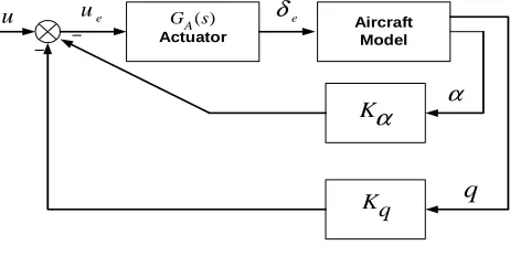
At first, we design SAS where typically uses sensors to measure the body-axis angular rates of the vehicle, and feedback processed versions of these signals to servomechanisms that drive the aerodynamic control surfaces. SAS conventionally designed separately for the longitudinal and the lateral-directional dynamics and this is made possible by the decoupling of the aircraft dynamics in most flight conditions as “in reference [8]”. The purpose of a pitch SAS is to provide satisfactory natural frequency and damping the short period. And if the frequency and damping are both unsatisfactory or the mode is unstable, usually an alpha feedback is necessary. “Fig.1” illustrates pitch axis stability with two feedbacks (q,α).
Aircraft Model Actuator ( ) A G s K
α
Kqu ue δe
α
q
Figure 1. Pitch- axis stability augmentation.
Then, we design PI controller for pitch attitude and the block diagram of pitch attitude is shown in “Fig.2”. Where
( )
c
having the following time domain performances: 1. Zero Steady-State Error (Zero-SSE). 2. Controllable settling time Ts.
3. Minimum rise time Tr90 (0-90% of the step height).
4. Percent Overshoot (P.O) and Percent Undershoot (P.U) less than 2%.
Aircraft Model Actuator ( ) A G s K
α
Kqu ue
δ
eα
q
Attitude Gyro C θθ
( ) c G sFigure 2. Pitch-attitude autopilot.
Fly at nonlinear flight region (high angle of attack); strongly depend to aerodynamic characteristics of aircraft. The designed controller should have an acceptable level of robustness to aerodynamic uncertainty. There are different aerodynamic derivatives in Longitudinal /
Lateral-Directional axis which have their influences in the equations of motion. It is shown that aerodynamic uncertainty data consist of increments or percentage variations in the important aerodynamic coefficients and derivatives as follow as “in references [11, 12]”:
(
50% ;)
(
10% ;)
( 5%) q, q, q(
10%)
L m D L m D
С С С andС С С
α ± α ± α ± ±
(4)
4. Case Studies Simulations
This section presents the simulation results to design SAS and pitch hold using classical PI controller to the high-fidelity F-16 model at high angle of attack including aerodynamic uncertainties as “equation 4”. It is noted that simulation results are showed for linear (“equation 2”) and nonlinear model (“equation 1”) of aircraft at high angle of
attack. In this study, we make an investigation of robustness of designed controller in high angle of attack region for variation of speed between stall speed (Vstall) and minimum controllable speed (Vmin (1.05VStall)) and a mean speed ((Vstall <Vselected <Vmin).Different case studies “Table . 1” are as follow:
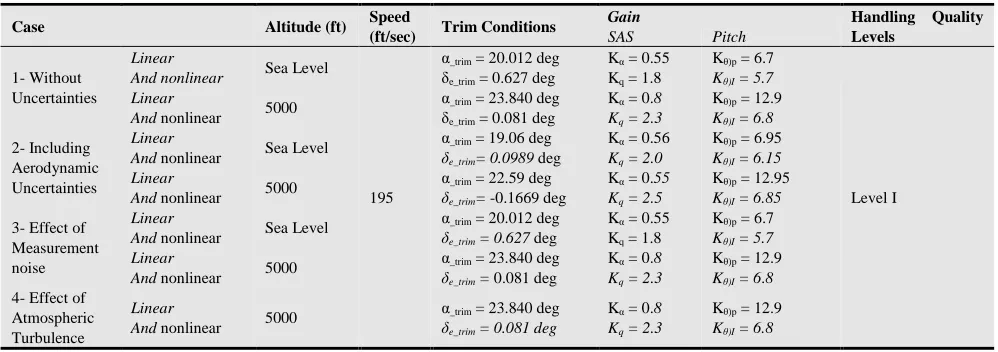
Table 1. Design case studies.
Case Altitude (ft) Speed
(ft/sec) Trim Conditions
Gain Handling Quality
Levels
SAS Pitch
1- Without Uncertainties
Linear
And nonlinear Sea Level
195
α_trim = 20.012 deg
δe_trim = 0.627 deg
Kα = 0.55
Kq = 1.8
Kθ)p = 6.7
Kθ)I = 5.7
Level I Linear
And nonlinear 5000
α_trim = 23.840 deg
δe_trim = 0.081 deg
Kα = 0.8
Kq = 2.3
Kθ)p = 12.9
Kθ)I = 6.8
2- Including Aerodynamic Uncertainties
Linear
And nonlinear Sea Level
α_trim = 19.06 deg δe_trim= 0.0989 deg
Kα = 0.56
Kq = 2.0
Kθ)p = 6.95
Kθ)I = 6.15
Linear
And nonlinear 5000
α_trim = 22.59 deg δe_trim= -0.1669 deg
Kα = 0.55
Kq = 2.5
Kθ)p = 12.95
Kθ)I = 6.85
3- Effect of Measurement noise
Linear
And nonlinear Sea Level
α_trim = 20.012 deg δe_trim = 0.627 deg
Kα = 0.55
Kq = 1.8
Kθ)p = 6.7
Kθ)I = 5.7
Linear
And nonlinear 5000
α_trim = 23.840 deg δe_trim = 0.081 deg
Kα = 0.8
Kq = 2.3
Kθ)p = 12.9
Kθ)I = 6.8
4- Effect of Atmospheric Turbulence
Linear
And nonlinear 5000
α_trim = 23.840 deg δe_trim = 0.081 deg
Kα = 0.8
Kq = 2.3
Kθ)p = 12.9
Kθ)I = 6.8
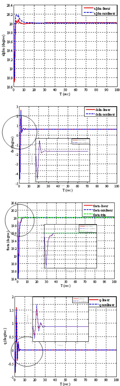
4.1. Case 1
Investigation about effect of linear and nonlinear mathematical model to the designed controller. Simulation results are shown in “Fig 3”. As illustrated in “Fig 3”, type of modeling (linear / nonlinear), have the same time response.
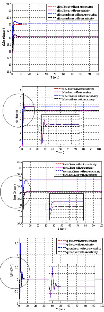
4.2. Case 2
and pitch attitude controller are robust with respect to aerodynamic uncertainty. Also, in “Fig.5”, effect of variation of altitude (from sea level to 30,000 ft.) and speed (from Vstall <Vselected <Vmin at each altitude) on variation of designed gain (e.g. gain scheduling) is presented.
4.3. Case 3
In this case, we make an investigation on time response of the designed SAS and pitch attitude controller to measurement noise and atmospheric turbulence. Measurement noise considers as an unstructured uncertainties where caused by imperfections in the sensors used to measure the output, and usually occurs at higher frequencies than the natural frequencies of the closed-loop system. To reduce the sensitivity of a closed-loop system to measurement noise (or to make the system robust with respect to measurement noise), the frequency response of the closed-loop system must have smaller gains at higher frequencies. Band-Limited White Noise” block for the measurement noise is used in simulation to study the effect of the noise on flight control system. In this paper is used “Noise power” parameter of the “Band-Limited White Noise” block to study this effect (i.e. we select value of 0.0001 for noise power as “in reference [13]”). “Fig.6” illustrates the results for these cases from noise power for linear and nonlinear model together. As indicated in “Fig.6”, the designed SAS and pitch attitude controller are robust with respect to noise.
4.4. Case 4
Finally, we make an investigation about effect of atmospheric turbulence on pitch hold, where atmospheric turbulence implementation are based on Dryden turbulence spectrum and handling qualities levels are defined from MIL_F_8785C as “in references[14 to 17,20]”. In this study Dryden turbulence is generated with the following parameters: flight altitude (H=5000 ft), velocity (V=195 ft/sec), and moderate intensity. “Fig. 7” illustrates the results for these cases from Dryden turbulence with moderate intensity for linear and nonlinear model together.
5. Conclusion and Discussion
In this paper, SAS and pitch attitude control for a modern type fighter has been developed based on classical PI techniques. It is demonstrated in numerical simulations that desirable handling qualities are achieved for high-fidelity F-16 model over a wide nonlinear flight region. Simulation results show that the designed SAS and controller are robust in time response with respect to aerodynamic uncertainties, measurement noise and atmospheric turbulence. Since the controller parameters are computed in advance and the tuning procedure is limited only to the cascade gain, the framework also provides an efficient and practical way for real-time PI parameter tuning.
Figure 4. Aircraft responses at case 2 (V=195 ft/sec; H: Sea Level)
0 10 20 30 40 50 60 70 80 90 100 18.4 18.6 18.8 19 19.2 19.4 19.6 19.8 20 20.2 20.4 T (sec) th e ta ( d e g re e )
theta-linear with noise power=0.0001 theta-nonlinear with noise power=0.0001
0 10 20 30 40 50 60 70 80 90 100 -4 -3 -2 -1 0 1 2 3 4 T (sec) d e ( d eg re e )
delta-linear with noise power=0.0001 delta-nonlinear with noise power=0.0001
Figure 6. Aircraft responses to noise, case 3 (V=195 ft/sec; H: Sea Level).
0 10 20 30 40 50 60 70 80 90 100 22 22.5 23 23.5 24 24.5 T (sec) th e ta ( d e g re e )
theta-linear with turbelence moderate theta-nonlinear with turbelence moderate
0 10 20 30 40 50 60 70 80 90 100 -7 -6 -5 -4 -3 -2 -1 0 1 2 3 T (sec) d e ( d e g re e )
delta-linear with turbelence moderate delta-nonlinear with turbelence moderate
Figure 7. Aircraft responses at Case 4, with turbulence Dryden moderate
model.
References
[1] L. Sonneveldt, E.R. van Ort, Q.P. Chu and J.A. Mulder, “Nonlinear Adaptive Flight Control Law Design and Handling Qualities Evaluation,” IEEE Conference on Decision and Control, China, December 16-18, 2009.
[2] Michael V. Cook, “Flight Dynamics Principles”, Second Edition, ISBN:978-0-7506-6927-6, 2007.
[3] Yake, Bradley Gerald, “Investigation of Fore body Strakes on Aircraft Stability at High Angle of Attack”, Master of Science in aerospace engineering, University of Texas at Arlington 1991.
[4] Russell M. Cummings, James R. Forsythe, Scott A. Morton, , Kyle D.Squires,” Computational challenges in high angle of attack flow prediction”, Aerospace Engineering Department, California Polytechnic State University, San Luis Obispo, CA 93407, USA ,2003.
[5] David Allerton, “PRINCIPLES OF FLIGHT
SIMULATION”, Aerospace Series, ISBN:
978-0-470-75436-8 (Hbk), the University of Sheffield, 2009.
[6] B. Kada, Y. Ghazzawi, “Robust PID Controller Design for an UAV Flight Control System” , Proceedings of the World Congress on Engineering and Computer Science, Vol II, ISSN: 2078-0966 (Online), 2011.
[7] L. T. Nguyen, M. E. Ogburn, W. P. Gilbert, K. S. Kibler, P. W. Brown, and P. L. Deal, “Simulator study of stall post-stall characteristics of a fighter airplane with relaxed longitudinal static stability”, tech. rep., NASA Langley Research Center, 1979.
[8] B. L. Lewis and F. L. Stevens,” Aircraft Control and Simulation”, pp. 1–54,110–115. John Wiley & Sons, 1992.
[9] Chao Wang, “Aircraft Autopilot Design using a Sampled Data Gain Scheduling Technique”, Master of Science, College of Engineering and Technology Ohio University, March, 1999.
[10] Albert Farre Gabernet,” Controllers for Systems with Bounded Actuators: Modeling and control of an F-16 aircraft”, Master of Science, University of California, Irvine, 2007.
[11] Brent R. Cobleigh, “Development of the X-33 Aerodynamic Uncertainty Model”, Dryden Flight Research Center, Edwards, California 93523-0273, NASA/TP-1998 -206544 , 1998.
[12] Jan Roskam,” Airplane Flight Dynamics and Automatic Flight Controls”, Part I, ISBN 1-884885-17-9, Copyright ©1995-2001 by Dr. Jan Roskam in United States of America.
[13] Ashish Tewari, “Modern Control Design with Matlab and Simulink”, Indian Institute of Technology, Kanpur, India, ISBN 0 471 496790, Copyright © 2002 by John Wiley & Sons Ltd.
[14] Military Standard - Flying Qualities of Piloted Airplane, MIL-F-8785C, 1980.
[15] "Dryden Wind Turbulence Model Continous),"
MATHWORKS, [Online]. Available:
[16] P. W. Gibbens,D. P. Boyle, ” FLIGHT MECHANICS 2”, Lecture Notes, AERO 4500, University of Sydney Department of Aeronautical Engineering, 1999.
[17] Borja Martos, “Identifying and Correcting First Order Effects in Explanatory Variables for Longitudinal Real Time Parameter Identification Methods in Atmospheric Turbulence”, University of Tennessee, Knoxville, Trace: Tennessee Research and Creative Exchange, Doctoral Dissertations, Copyright © 2013 by Borja Martos.
[18] Mullapudi Jyothi, Tadikonda Poojitha, Y V Pavan Kumar, Dr. K Babulu, “A Comparative Study on Flight Control Systems Design Using Conventional vs. Statistical Methods”, IJSR
-INTERNATIONAL JOURNAL OF SCIENTIFIC
RESEARCH, Volume : 2 :Issue : 7 • SSN No 2277 - 8179, July 2013.
[19] T.Hanis, V. Kucera, M. Hromcik, "Low Order
H
∞ Optimal Control for ACFA Blended Wing Body Aircraft",EUROPEAN CONFERENCE FOR AEROSPACE
SCIENCES (EUCASS), ACFA2020 special session, 2011.