Impact of Parametric Variations on Chaotic
Behaviour of Indirect Field Controlled
Induction Motor Drives
Mirza Abdul Waris Begh
∗1, Bharat Bhushan Sharma
#2∗Chair of Power Electronics and Drives, Technical University of Munich, Germany #Department of Electrical Engineering, NIT Hamirpur, H.P., India
1
[email protected],[email protected]
Abstract—Controlling complex chaotic systems and analyz-ing their behavior have emerged as an attractive field of exploration in different domains of engineering. Over the years, large number of mathematical tools are developed to identify and control the typical behaviour of these systems. The work presented in this manuscript explores chaos in nonlinear dynamics of an indirect field controlled induction motor drive system. For this exploration, impact of variation in rotor inductance is considered while assuming the load torque to be fixed. Chaotic attractors are first verified by investigating Lyapunov Exponents. The range of parametric variation is explored to check for the events where chaos can creep into the system again. Finally, an attempt is made to measure the transition point between stability and instability of the chaotic system. This is verified using the Lyapunov Exponent measure and the phase plots. The detailed simulation results highlight the efficacy of the methodology to identify the chaotic behaviour of the induction motor.
Keywords—Chaotic behaviour, Field Controlled Induction Motor, Hopf Bifurcation, Chaos Control.
I. INTRODUCTION
The general perception on chaos is equivalent to disorder or complete randomness. It should be noted that chaos is not exactly disordered, and its random-like behaviour is math-ematically governed by a deterministic model or equations that contain no element of chance [1]. The advances in understanding and analyzing nonlinear systems have shown that the phenomenon of typical chaotic behavior may be attributed to certain systematic rules rather than linking it to arbitrariness. The intriguing aspect of chaotic systems is that even though their description can be made by following deterministic models, their sensitiveness to small perturbation in initial conditions renders them almost impossible to ac-curately predict their future behavior [2]. Along with that, plot of the trajectories of these systems in phase plane exhibit their important trait of non-settling to a particular equilibrium point or to a periodic orbit, but still remaining structurally stable while exhibiting strange attractors. Chaotic systems find
reference in variety of fields like chemical systems, physi-cal systems, electronic systems, electro-mechaniphysi-cal systems, biological systems, economical systems etc. Main thrust in all these areas is to identify chaotic behaviour, control and suppression of such behaviour and to utilize the benefits of this aspect in certain application fields like secure communica-tion, encryption/decryption of informacommunica-tion, pattern formacommunica-tion, chemical mixing etc. Various nonlinear control techniques are utilized to achieve all these objectives [3]-[12].
The investigation of chaotic behaviour in electric drives is an area of open interest due to direct applications of these drives in many areas, such as, industrial processes, electrical loco-motives etc.[13]-[18]. For instance, feedback based linear and nonlinear controllers were proposed to control and synchronize the systems with chaotic dynamics by Rafikov et al. [19]. A global feedback control methodology utilizing measurement of the maximum amplitude of associated pattern in the domain of interest, which leads to stability of the system, was proposed by Golovin et al. [20]. The presence of chaos in an induction motor was investigated and a sliding mode technique (SMT) based controller was proposed by D. Chen et al. [21]. In this work, indirect field control based nonlinear dynamical model of induction motor drive was presented and the typical nonlinear behavior of the system model was analysed using bifurcation diagrams, phase portraits etc. Moreover, a sliding mode control method was also presented.
exponents are predominantly used to characterize different behaviours exhibited by nonlinear systems. The number of Lyapunov exponents for a given dynamical system is equal to the number of associated state variables. These Lyapunov exponents may turn out to be positive, negative, or zero. Using Lyapunov exponent plots, we investigate the chaotic nature of the system and then by parameter variation, effort is made to either eliminate the system chaos or chaotify the system. For this purpose, impact of varying rotor inductance is considered while considering the load torque to be fixed. Further, bifurcation analysis is presented to identify the range of parameters for which the induction motor exhibit chaotic behaviour. Detailed simulations are presented in the end to highlight the efficacy of proposed methodology.
The paper is organised as follows. In Section 2, the nonlinear model of induction motor drive with current control, in a reference frame assumed to be rotating at synchronous speed, is discussed. Section 3 presents the method used to compute the Lyapunov exponents. Section 4 discusses the presence of chaos and its elimination from the system using Lyapunov plots. Section 5 discusses the chaotification of the system by parameter variation and this is verified using Phase plots, Hopf bifurcations and Lyapunov exponent plots. Finally, concluding remarks regarding the proposed work are presented in Section 6.
II. DYNAMICMODEL OF THEINDUCTIONMOTOR
The model of a current-driven induction machine (developed by W. Leonhard in 1996) used for the analysis in [21] is reproduced here. This model is expressed in a reference frame which is assumed to be revolving at synchronous speed. The associated mathematical dynamic model is given as follows:
˙
ψqr=−
Rr
Lr
ψqr−ωslψdr+
Lm
Lr
Rriqs
˙
ψdr=−
Rr
Lr
ψdr−ωslψqr+
Lm
Lr
Rrids (1)
˙
ωr=−
Rω
J ωr+
1 J 3 2 Lm Lr
np(iqsψdr−idsψqr)−TL
where Rr is rotor resistance, Lr is rotor self-inductance,
Lm is mutual inductance in a rotating reference frame,np is
the number of pole pairs,ωsl is slip frequency,ωris angular
speed of the rotor, J is inertia coefficient, TL is load, ψqr
is rotor flux component associated with quadrature axis, ψdr
is direct axis component of the rotor flux. The parameters of motor model presented in (1) are substituted with constants defined as below:
c1 =
Rr Lr
, c2=
Lm Lr
Rr, c3=
Rω J , c4=
1 J, c5=
3 2
Lm Lr
np (2)
The state variables and control inputs are defined as:
x1=ψqr,x2=ψdr,u1=ωsl,u2=ids,u3=iqs (3)
Therefore, the dynamics of induction motor drive with indirect field control, in state space form, can be rewritten as follows:
˙
x1=−c1x1−u1x2+c2u3
˙
x2=−c1x2+u1x1+c2u2 (4)
˙
ωr=−c3ωr+c4[c5(x2u3−x1u2)−TL]
In industrial applications associated with regulating the speed of motor, the indirect field oriented control is usually used. This scheme employs a proportional plus integral (PI) speed loop. This control scheme is described as follows:
u1=cb1
u3
u2
u2=u02 (5)
u3=Kp(ωref −ωr) +Ki Z t
0
ωref(ζ)−ωr(ζ))dζ
where cb1 is the estimate for the inverse rotor time constant
c1,ωref is the constant reference velocity,u02 is the constant
reference for the rotor flux magnitude,Kp is the proportional
gain and Ki is the gain associated with integral part of PI
speed regulating element.
Ifcb1= c1 i.e.cb1 is a correct estimation of time constant of
rotor, then control is said to be tuned. Otherwise, control is termed to be detuned. In such case, degree of tuning is taken as k=cb1/c1. Obviously, the controller is tuned and one sets
k= 1. Let us assumex3=ωref−ωrandx4=u3. The above
selections lead to a new fourth dimensional model, which is derived from the model of close loop system represented by equation (4) and the corresponding control strategy (5). The new model can be written as follows:
˙
x1=−c1x1+c2x4−
kc1
u0 2
x2x4
˙
x2=−c1x2+c2u02+
kc1
u0 2
x1x4 (6)
˙
x3=−c3x3−c4
c5(x2x4−x1u02)−TL−
c3
c4
ωref
˙
x4= (ki−kpc3)−kpc4
c5(x2x4−x1u02)−TL−
c3
c4
ωref
III. COMPUTATION OF THELYAPUNOVEXPONENTS (LES)
In case of chaotic systems, Lyapunov exponents are con-sidered as average exponentially convering or diverging rates of nearby trajectories of a given system in phase space. The qualitative behavior of the systems dynamics can be linked to the signs of the Lyapunov exponents. One dimensional systems have a single characteristic Lyapunov exponent which is positive for chaotic regime, zero for a marginally stable orbit, and negative for a periodic attractor. Lyapunov exponents as measure of chaotic nature have been utilized to analyze nonlinear phenomena which are localized in time and/or space. For example, these measures have been used in analyzing fluid mixing along the mixing chamber’s border as highlighted in [29]. The methodology used for the computation of the LEs was motivated by the approach proposed by Bennetin et al [30] and the work highlighted by Shimada et al. [31] for obtaining a complete spectrum from a given differential description. Overall, Lyapunov exponent gives us the average rate of separation of two adjacent orbits of the dynamical system which are very close to each other at time t = 0. Quantitatively, the rate of divergence of two nearby trajectories in phase space with small separation in initial conditions is given as
|δx(t)|=eλt|δxo| (7)
whereλis the Lyapunov exponent.
The above rate of divergence can be different for different orientations of initial separation vector. Thus, the spectra of Lyapunov exponents exists with number of LEs equal to the dimension of the associated phase space. The largest Lyapunov exponent is commonly referred as the Maximal Lyapunov exponent (MLE), because it determines a notion of predictability for a given system. A positive MLE is a indicator of underlying chaotic behaviour of the system.
In case of nonlinear system with evolution dynamicsf(x)
in an n-dimensional phase space, the Lyapunov exponents measures λ1, λ2,..., λn generally are dependent on initial
conditionxo. These Lyapunov exponents characterize the
be-haviour of state trajectories in the tangent space of phase space. These are described in terms of Jacobian matrix computed as follows:
Q(xo) =
df(x)
dxo
x=xo
(8)
TheQmatrix describes how a small perturbation in the initial pointxo propagates in the long run to final point f(xo).The
limit
lim t→∞(Q.Q
T)1/2t
(9)
defines a matrix L(xo). IfΛi(xo)denotes the eigenvalues of
L(xo), then the LEs are expressed as follows [32]:
λi(xo) =logΛi(xo) (10)
IV. ANALYSIS OFCHAOS IN THESYSTEM
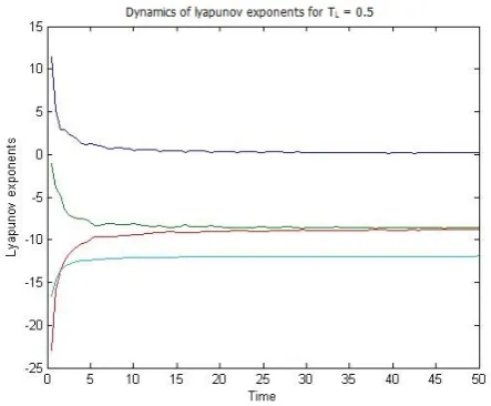
In the work presented in [21] the authors have empha-sized the presence of chaos using phase portraits, bifurcation diagrams and Poincare maps. Lyapunov exponents, which may efficiently indicate whether a system is chaotic or not, were not used. We first present the Lyapunov exponents plot depicting the systems chaotic nature. To simulate the system of equations obtained in (6) the parameters are chosen as, c1 = 13.67, c2 = 1.56, c3 = 0.59, c4 = 1176, c5 =
2.86, u2
0 = 4, kp = 0.001, ki = 1, k = 1.5, ωref = 181.1
with the load torque TL = 0.5 and the initial states set to
x1 = 0, x2 = 0.4, x3 = −200, x4 = 6. The simulations
and results are shown in Fig. (1). From Fig. (1), it is clearly
Fig. 1: Dynamics of Lyapunov exponents atTL= 0.5.
concluded that one of the Lyapunov exponent measure is positive in the given range, irrespective of the time, which implies that the trajectories are diverging continuously with time. It indicates that the system is behaving in a chaotic manner for very small loads. When the load is increased to a higher value(> TL= 8.5), then as indicated by the Lyapunov
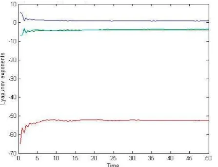
exponent plot in Fig. (2) all the values are negative depicting nonchaotic behaviour.
From Fig. (2) we observe that by increasing the motor load significantly all the Lyapunov exponents turn out to be negative thereby concluding that system chaos can be affected by increment in the load.
V. CHAOTIFICATION OF THESYSTEM USING PARAMETERVARIATION
In this section, the chaotic behaviour onset is explored for the induction motor by using parameter variation. To induce chaos, the Lyapunov exponents of the closed loop system should evolve in such a way that at least one of these Lyapunov exponent measures remain positive.
Fig. 2: Dynamics of Lyapunov exponents at TL= 8.5.
reluctance) the system behaves chaotically irrespective of the load TL. To decrease the rotor inductance (Lr), parameters
c1, c2, c5 must change asLris common in all of them. If the
modified rotor inductance is L0r , the new set of parameters will be:
c1=
Rr L0r
, c2=
Lm L0r
Rr, c3=
Rω J , c4=
1 J, c5=
3 2
Lm L0r
np (11)
Let us define a new ratio r=Lr/L
0
r. To decrease the rotor
inductance ratioris set as10and the modified set of param-eters used for analysis becomesc1 = 136.7, c2= 15.6, c3 =
0.59, c4 = 1176, c5 = 28.6, u20 = 4, kp = 0.001, ki = 1, k = 1.5, ωref = 181.1 with the load torque TL = 8.5 and the
initial states set tox1= 0, x2= 0.4, x3=−200, x4= 6.
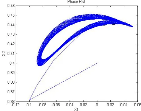
The phase portraits obtained by simulating the system (6) using the parameters given above are shown in the figures (3)-(6):
Fig. 3: 2-dimensional phase portrait betweenx2 andx4.
Fig. 4: 2-dimensional phase portrait betweenx1 andx2.
Fig. 5: 2-dimensional phase portrait betweenx1 andx4.
From figures (3)-(6), we clearly infer that the system exhibits chaotic nature because the response settles in an attractor, which is a distinctive feature of chaotic systems. The analysis presented here considers the parametric variations arising from assuming rotor inductance as variable with load torque as fixed whereas the chaotic behaviour of field oriented control based induction motor model for variable load and by varying parameters of PI controller can be found in [13]. To justify the chaotic nature of the system as investigated above, using phase portraits, we now try to present the analysis using Hopf Bifurcations.
Fig. 6: 3-dimensional phase portrait between x1 and x2 and
x3.
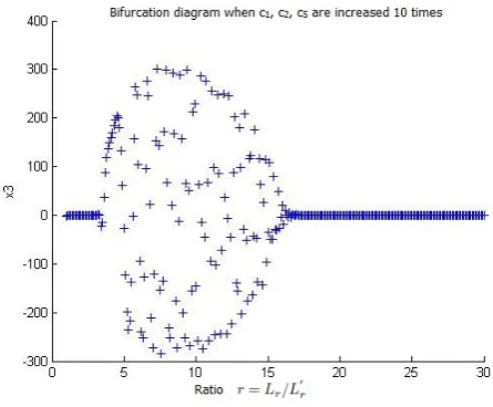
The bifurcation plots in figures (7)-(10) are plotted for varying ratio of rotor inductance w.r.t. state variables. From figures (7)-(10) we observe that the system loses its periodicity and shows chaotic behaviour whenever the rotor inductance is decreased by the ratio lying within{5, 15}. This implies that the system is not chaotic when ratio is higher than 15.
Fig. 7: Hopf bifurcation for state x1 v/s r with c1, c2, c5
increased 10 times.
The analysis is further extended by observing the Lyapunov exponents plot for the system with new set of parameters and we can see from Fig. (11) that one of the exponents is always positive proving that by parameter variation chaos can creep into a non-chaotic system. To justify the inexistence of chaos whenever the rotor inductance is decreased by a ratio higher than 15, we present a Lyapunov exponent plot in Fig. (12) which clearly shows that system is not chaotic.
Fig. 8: Hopf bifurcation for state x2 v/s r with c1, c2, c5
increased 10 times.
Fig. 9: Hopf bifurcation for state x3 v/s r with c1, c2, c5
increased 10 times.
VI. CONCLUSION
Fig. 10: Hopf bifurcation for state x4 v/s r with c1, c2, c5
increased 10 times.
Fig. 11: Variation of Lyapunov exponents with time at TL = 8.5and ratio r= 10.
REFERENCES
[1] K. T. Chau and Z. Wang. Chaos in electric Drive Systems Analysis, Control and Application, Wiley-IEEE Press,Singapore (2011).
[2] Mohamed Zribi, Ahmed Oteafy and Nejib Smaoui, Controlling chaos in the permanent magnet synchronous motor, Chaos, Solitons and Fractals, 41, 1266-1276 (2009).
[3] R. Femat, R.J. Ortiz, and G.S. Perales, A chaos based communication scheme via robust asymp- totic feedback, IEEE Trans. on Circuits and Systems, Part I, vol. 48, no. 10, pp. 11611169, (2001)
[4] S. Callegari, R. Rovati and G. Setti , Chaos-based FM signals: applica-tions and implementation issues, IEEE Trans. on Circuits and Systems, Part I, vol. 50, no. 8, pp. 11411147, (2003).
[5] B.B. Sharma and I.N. Kar, Parametric convergence and control of chaotic system using adaptive feedback linearization, Chaos, Soliton and Fractals, vol. 40, pp. 1475-1483, (2009).
[6] B.B. Sharma and I.N. Kar, Contraction theory based adaptive synchro-nization of chaotic systems, Chaos, Soliton and Fractals, vol. 41, no. 5, pp. 2437-2447, (2009).
[7] M.T. Yassen, Controlling chaos and synchronization for new chaotic system using linear feedback control, Chaos Solitons Fractals vol. 26, pp. 913920, (2005).
Fig. 12: Variation of Lyapunov exponents with time at TL= 8.5 and ratior >15.
[8] Y. Wang, Z.H. Guan and H.O. Wang, Feedback and adaptive control for the synchronization of Chen system via a single variable, Phys. Lett. A, vol. 312, pp. 3440 (2003).
[9] H. Handa and B.B. Sharma, Novel adaptive feedback synchronization scheme for a class of chaotic systems with and without parametric uncertainty, Chaos, Soliton and Fractals, vol. 86, pp. 50-63, (2016). [10] H. Handa and B.B. Sharma, Simple synchronisation scheme of chaotic
Chuas systems with cubic nonlinearity in complex coupled networks, Int. J. Applied Nonlinear Science, Vol. 1, No. 4,pp. 300-311, (2014). [11] C. Wu, and Y.C. Lee, Observer-based method for secure communication
of chaotic systems, IET Control Theory Applications, vol. 36, no. 22, pp. 18421843, (2000).
[12] F. Zhu, J. Xu, M. Chen, The combination of high-gain sliding mode observers used as receivers in secure communication, IEEE Trans. on Circuits and Systems, Part I, vol. 59, no. 11, pp. 27022712, (2012). [13] N. Jabli, H. Khammari, M. F. Mimouni, R. Dhifaoui, Bifurcation and
chaos phenomena appearing in induction motor under variation of PI controller parameters, WSEAS Transactions on Systems, vol. 9, no. 7, pp. 784-793, (2010)
[14] R. Sangrody and S.M. Shariatmadar, A Lyapunov Function for Vector Control Drives in Induction Machines, Engineering, Technology Applied Science Research, vol. 6, no. 5, pp. 1167-117, (2016).
[15] M. Zribi, A. Oteafy and N. Smaoui, Controlling chaos in the permanent magnet synchronous motor, Chaos, Solitons and Fractals, vol. 41, pp. 12661276 (2009).
[16] Y. Huang, Controlling Chaos in Permanent Magnet Synchronous Motor, Chemical Engineering Transactions, vol. 46, pp. 1183-1188 (2015). [17] J.K. Seok, J.K. Lee and D.C. Lee, Sensorless speed control of nonsalient
permanent-magnet synchronous motors using rotor-position-tracking PI controller, IEEE Trans. Ind. Appl., no. 53, pp. 399-405 (2006). [18] H. Trabelsi and M. Benrejeb, Control of chaos in permanent magnet
synchronous motor with parameter uncertainties: a Lyapunov approach, International Journal of Innovation and Scientific Research, Vol. 13 No. 1, pp. 279-285 (2015)
[19] M. Rafikov and J. M. Balthazar, Control and synchronization in chaotic and hyperchaotic systems via linear feedback control, Communications in Nonlinear Science and Numerical Simulation, vol.13, no.7, 1246-1255 (2008).
[20] A. A. Golovin, Y. Kanevsky and A. A. Nepomnyashchy, Feedback control of subcritical Turing instability with zero mode, Physical Reiview E, vol.79, no.4, 046218 (2009).
[21] Diyi Chen, Peng Shi and Xiaoyi Ma, Control and synchronization of chaos in an induction mo- tor system, International Journal of Innovative Computing, Information and Control, Volume 8, Number 10(B), 7237-7248 (2012).
[23] A. Wolf, J. B. Swift, H. L.Swinney, J. A. Vastano, Determining Lya-punov exponents from a time series, Physica D:16, 285317 (1985). [24] W. Kinsner, Characterizing chaos through Lyapunov metrics, IEEE Trans
Syst Man Cybernet , 36(2), 141151, (2003).
[25] C. Li, G. Chen, Estimating the Lyapunov exponents of discrete systems. Chaos: An Interdisci- plinary J Nonlinear Science, 14(2),343-346 (2004). [26] A.Stefanski , T. Kapitaniak. Estimation of the dominant Lyapunov exponent of non-smooth systems on the basis of maps synchronization, Chaos, Solitons and Fractals, 15(2),233-244 (2003).
[27] S.L.T De Souz, I.L. Caldas, Calculation of Lyapunov exponents in systems with impacts, Chaos, Solitons and Fractals, 23(3), 569579 (2004). [28] O. Alvarez-Llamoza, M.G. Cosenza, G.A. Ponce, Critical behavior of the Lyapunov exponent in type-III intermittency, Chaos, Solitons and Fractals, 36, 150156 (2008).
[29] A. Jayaraman , J. Scheel , H. Greenside , P. Fischer, Characterization of the domain of chaos convection state by the largest Lyapunov exponent, Phys Rev E,74(016209) (2006).
[30] G. Benettin, L. Galgani, A. Giorgilli and J.-M. Strelcyn, Lyapunov Char-acteristic Exponents for Smooth Dynamical Systems and for Hamiltonian Systems; A Method for Computing All of Them, Meccanica 15 (1980). [31] I. Shimada and T. Nagashima, A Numerical Approach to Ergodic
Problem of Dissipative Dy- namical Systems, Prog. Theor. Phys. 61, 1605,(1979).
[32] M. Cencini, Chaos From Simple models to complex systems,World Scientific, ed.(20101)