http://www.sciencepublishinggroup.com/j/ijmsa doi: 10.11648/j.ijmsa.20190802.13
ISSN: 2327-2635 (Print); ISSN: 2327-2643 (Online)
Two Different Loading Directions to Determine the Shear
and Longitudinal Modulus of Elasticity
Edson Fernando Castanheira Rodrigues
1, *, André Luis Christoforo
21
School of Civil Engineering, University of Uberaba, Uberaba, Brazil
2Department of Civil Engineering, Federal University of São Carlos, São Carlos, Brazil
Email address:
*
Corresponding author
To cite this article:
Edson Fernando Castanheira Rodrigues, André Luis Christoforo. Two Different Loading Directions to Determine the Shear and Longitudinal Modulus of Elasticity. International Journal of Materials Science and Applications. Vol. 8, No. 2, 2019, pp. 30-34.
doi: 10.11648/j.ijmsa.20190802.13
Received: May 7, 2019; Accepted: June 6, 2019; Published: July 4, 2019
Abstract:
The large-scale abundance of wood in Brazil combined with the advantages of its use stimulate many studies to be encouraged in order to make use of this raw material in a more optimized and adequate form. Compared with concrete and steel, wood presents an excellent relation between mechanical strength and its mass, beauty, low energy consumption for its processing, good thermal insulation and easy workability. Objectifying the best use of wood, this work proposes that the equivalence between longitudinal and transversal modulus of elasticity values with radial (ELR; GLT) and tangential load application (ELT; GLR) in the 3 and 4-point bending tests used for their determinations. The test of equivalence used in the analysis of the results for the modulus of elasticity was the Tukey’s test, by which the statistical equivalence between values of longitudinal (ELR x ELT) and transversal (GLT x GLR) modulus of elasticity with the radial and tangential load application, respectively. It was concluded that for the species of the hardwood group: Peroba Rosa (Aspidosperma polyneuron) with 35 specimens, Eucalyptus Tereticornis (Eucalyptus tereticornis) with 33 specimens, Jatobá (Hymenaea courbaril) with 28 specimens and Canafístula Peltophorum dubium) with 12 test specimens, tested in this work, there was no significant influence of the direction change of the loads on the values of the calculated modulus of elasticity.Keywords:
Equivalence Test, Hardwoods, Radial Load, Tangential Load, Different Directions1. Introduction
Wood was always one of the materials of civil construction most used by the human being. The physical and mechanical characteristics and relative abundance of this material enable its application for uses from interior finishes to large structures such as pavilions, roofs and bridges. Wood presents environmental advantages when compared to other building materials (cement, concrete, steel and aluminum), because it is recyclable, renewable, biodegradable and requires low energy needs for its processing [1-4].
In relation to other materials such as concrete, plastic, steel and aluminum, wood has a number of advantages, such as beauty, high mechanical resistance to mass, low energy consumption for its processing, good thermal insulation, easy workability [5].
Getting to know the importance of wood, it is important to carry out studies on obtaining its physical and mechanical characteristics. In the last case, wood can be used even as a fuel substituting the diminishing fossil energy carriers. [6]
Regarding the mechanical characteristics, we have the elasticity modulus that measures the stiffness of the specimens, however, it is necessary to carry out tests with the maximum of accuracy, as an example of this, the definition of the direction of application of the load in the test.
Among the mechanical properties of materials used in the design of a structure, highlights the modulus of elasticity (MOE), enabling the setting to provide displaced and deformations in structural components subjected to the action of the imposed loads (limit state) [7-9].
of elasticity of wood through the 3-point bending test, which can be found in its Annex B as well as the measurements of the specimens used and the test procedure. In this test a specific direction of application of the load is not stipulated, this load can be either in the radial or tangential longitudinal direction.
The Brazilian standard imposes that the deformations (arrows) in the bending test should be a maximum of L/200, (L being the length between supports), so that the piece of wood tested does not extrapolate the elastic regime for the plastic.
Icimoto et al. [8], performed tests varying the direction of load application (sides A, B, C and D) on test specimens tested by 3 point bending, as prescribed by the Brazilian standard, for 6 specimens for each species of Corymbia Citriadora (hardwood) and Pinus Elliottii (conifer), and each test specimen was tested 4 times. The results were compared by analysis of variance and it was found that for these species the position of the load application did not significantly change the values of longitudinal modulus of elasticity, but with an observation that this analysis can not be extended to other species, since wood is an orthotropic material.
Lahr et al. [11] tested some species of the hardwood group: Cedrinho (Erisma uncinatum), Peroba Rosa (Aspisdosperma polyneuron), Eucalyptus Tereticornis (Eucalyptus tereticornis), Canafístula (Cassia ferruginea), Jatobá (Hymenaea stilbocarpa). The 3- and 4-point bending tests were performed with tangential and radial load application to determine the longitudinal and transversal modulus of 20 specimens per species. The results were compared using the Anderson-Darling test, which showed equivalence between the longitudinal and transversal moduli of elasticity ELT × ELR and GLR x GLT, respectively.
Icimoto et al. [12], seven different species of the hardwood group were studied: Cambará Rosa (Erisma sp.), Eucalyptus Grandis (Eucalyptus Grandis), Cupiúba (Goupia Glabra), Eucalyptus Citriodora (Corymbia Citriodora), Ipe (Tabeluia sp.), Jatobá (Hymenaea stilbocarpa), Angico Rosa (Anadenanthera falcata) and one of the group of Conifers: Pinus Elliottii (Pinus Elliottii). Eight specimens were tested for each species, each specimen was tested 4 times, being a total of 4 different sides of the load application, so that all the faces of the specimen were tested. The results were tested by the least square methods and it was verified non-equivalence between the longitudinal modulus of elasticity with loads applied in different directions for the species studied.
Stolf et al. [13] performed a test to determine the longitudinal modulus of elasticity in three different positions (tangential, radial and radial farther from the core) in the equipment developed by Siqueira (1986), based on the FPL type machine (developed by the forest products laboratory-USA) using a modified Charpy pendulum. The principle of operation is characterized by kinetic energy provided by a pendulum via flexible current with a support at its end. The rupture of the tested piece is obtained by a simple movement of the pendulum. The calculations for stiffness determination were performed according to [14] ASTM D143-52 (ASTM 1981) for each species studied in the
hardwood group: Angelim Saia (Parkia pendula) with 13 pieces, Eucalyptus grandis with 32 pieces, Corymbia Citriodora with 20 pieces and conifers: Pinus elliottii with 35 pieces. The results were tested by Kruskal-Wallis non-parametric hardness analysis, and it was demonstrated that there was no significant change in the values with the load direction variation applied in the test.
2. Material and Methods
Three-point and four-point flexural tests were carried out to determine the values of the longitudinal modulus of elasticity with load application in the radial (ELR), tangential longitudinal (ELT) and transversal elastic modulus with load application in the tests in the radial (GLT) and tangential (GLR) longitudinal directions, remembering that ELR is referring to GLT and ELT referring to GLR, since G is always orthogonal to E.
The 3-point bending test performed is prescribed by ABNT NBR 7190 (Wood Structures Design) in Annex B, which shows the dimensions of the specimen as well as the test procedure, and the 4-point bending test according to [15] ASTM D 198-15 (Standard Test Method of Static Tests of Lumber in Structural Sizes) in an adapted manner, since the test pieces were not in structural size.
The species studied were: Peroba Rosa (Aspidosperma polyneuron) with 35 specimens, Eucalyptus Tereticornis (Eucalyptus tereticornis) with 33 specimens, Jatobá (Hymenaea courbaril) with 28 specimens and the Canafístula (Peltophorum dubium) with 12 specimens.
The values of ELR, Elt, GLT and GLR were taken into account for the species of the studied hardwood group. These results were compared by means of statistical analysis to prove the equivalence between ELR with ELT and GLT with GLR.
All tests were carried out on the Laboratory of Wood and Wood Structures (Laboratório de Madeira e de Estruturas de Madeira-LaMEM), at the São Carlos Engineering School (EESC), University of São Paulo (USP).
Initially, the four-point bending test was performed, based on ASTM D 198-15 (Standard Test Method of Static Tests of Lumber in Structural Sizes) for determination of modulus of elasticity in bending (E), expressed by equation 1. The arrow always limited to L/200 so that it does not exceed the limit of proportionality required in the Brazilian standard.
Source: author's collection.
Source: author's collection.
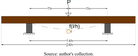
Figure 2. Representation of the 3-point bending test with its respective comparator clock.
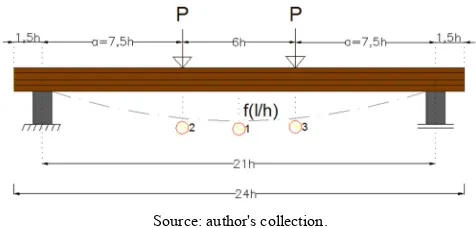
The arrows were measured by comparator clocks located only in the middle of the span (point 1 for 3-point bending test) and besides the middle of the span at the two points of load application (points 2 and 3 for 4-point bending test), P is the value of the applied loads, a is the distance from the load to the nearest support, L the length of the gap between supports (21h in the 4-point bending test and 14h in the 3-point test), can be seen in Figures 1 and 2.
The procedures for the two different tests performed to obtain E and G, which are the 4-point bending and the 3-point bending tests are described ahead.
2.1. Four-point Bending Test
The test specimens tested in 4-point bending followed the scheme of figure 1. According to the equation of the elastic line for this situation (equation 1), the appropriate formulations were used for the arrow at each required point.
(
² ²)
( ) 3 3
6 P a
v x L x x a
E I ⋅
= ⋅ ⋅ − ⋅ −
⋅ ⋅ (1)
In equation 1, v(x) is the arrow value at a given position, x is the position of the arrow analyzed, P is the value of the applied loads, a is the distance from the load to the nearest support, L the length of the span between supports, E the longitudinal modulus of elasticity and I is the moment of inertia.
It can be seen that in the central region between the loads, pure bending is generated when this type of test is performed, the total arrow in the center (point 1) was found according to equation 2. 4117, 5 (1) P v E b ⋅ =
⋅ (2)
Where P is the value of the applied loads, E the longitudinal modulus of elasticity found in the 4-point bendind test and b is the value of the cross-section base of the specimen.
Equation 3 represents the calculation of the arrow at load application points 2 and 3.
3826, 25
(2) (3) P
v v
E b ⋅
= =
⋅ (3)
Where, v(2) and v(3) are the arrows in positions 2 and 3 respectively, P is the value of the applied loads, E the longitudinal modulus of elasticity and b the value of the cross-sectional base of the specimen.
Getting to know the value of the total arrow in the middle of the span, the average between the two arrows at load application points 2 and 3 was subtracted from the total arrow, resulting in equation 4, which represents the relative arrow caused only by the flexion in the middle of the span [v(1rel)].
281, 25
(1 ) P
v rel
E b ⋅ =
⋅ (4)
Which, v(1rel) is the arrow in position 1 relating only to flexure, P is the value of the applied loads, E the longitudinal modulus of elasticity and b the value of the cross-sectional base of the specimen.
By isolating the only unknown value (E) from equation 4, we obtain equation 5. With this consideration the real E is found for any specimen.
281, 25 (1 )
P E
v rel b ⋅ =
⋅ (5)
2.2. Three-Point Bending Test
After the 4-point bending test, another test is performed, this time the simple 3-point bending test for the determination of G, which is shown in figure 2 presented before.
The 3-point bending test was performed as prescribed by ABNT NBR 7190 (1997) in its appendix B (determination of the properties for the structural design), but with a span between supports of 14h, in order to have the arrow with shear influence, allowing G to be found, since the real E has already been determined.
The Virtual Force Method (MFV) is used on the structural model of static bending at three points, aiming to find the expression for the calculation of the displacement below, the point of application of the force (equation 6), considering, therefore, the portion of the bending and shear stresses.
3 3 (1)
48 10
P L P L
v
E I G A
⋅ ⋅ ⋅
= +
⋅ ⋅ ⋅ ⋅ (6)
Which, v(1) is the arrow in the middle of the span, P is the applied point force, E is the longitudinal modulus of elasticity or Young's modulus, I is the moment of inertia of the cross section, G is the transversal modulus of elasticity, A is the cross-sectional area, L the useful length of the beam (distance between supports), b is the measurement of the base and h the height of the cross section respectively and A the value of the area.
Since the real E value has already been determined in the 4-point bending test, and that L = 14h, the only unknown value to be determined is G, thus turning into equation 7.
(
²)
126
30 (1) 1715
P h E I G
A E I v P h
⋅ ⋅ ⋅ ⋅ =
⋅ ⋅ ⋅ − ⋅ ⋅ (7)
3. Results and Discussion
and transverse elastic tests with radial (ELR e GLT) and tangential (ELT and GLR) load, respectively. The equivalence between the values of the elastic moduli by the Tukey’s test is confirmed by a value marked with the same letter in the level of 5% of reliability. In these tables the coefficient of variation (C. V.) can be seen for each group of test specimens tested.
Table 1. Equivalence analysis Through the Tukey’s test for the results of ELT
and ELR, with tangential and radial load application respectively in the tests.
ELT e ELR-Unity (MPa)
Medium Values ELT C. V. ELR C. V.
P. Rosa 10651 A 0,225 10870 A 0,153
E. Tereticornis 15610 A 0,146 15453 A 0,146
Jatobá 21237 A 0,283 21282 A 0,266
Canafístula 14788 A 0,160 14801 A 0,160
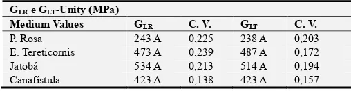
Table 2. Equivalence analysis Through the Tukey’s test for the results of GLT e
GLR, with radial and tangential load application respectively in the tests.
GLR e GLT-Unity (MPa)
Medium Values GLR C. V. GLT C. V.
P. Rosa 243 A 0,225 238 A 0,203
E. Tereticornis 473 A 0,239 487 A 0,172
Jatobá 534 A 0,213 514 A 0,194
Canafístula 423 A 0,138 423 A 0,157
The results of Table 1 for the values of longitudinal modulus of elasticity with tangential and radial load application indicate through the Tukey equivalence test that for all species tested there were equivalence for their respective modules (ELR x ELT), thus indicating that there is no need to perform the test with a load in a specific direction. This conclusion can be extended to Table 2, which for the transversal modulus of elasticity with radial and transverse loading, the values of the modulus were equivalent for all species tested (GLT x GLR), thus reaffirming there is no need for the application of the load in the bending test in an specific direction
Tables 1 and 2 diverge from the one presented by the study [12], where the change of direction of the load was preponderant for the tests, calling attention to the Jatobá species that in the present paper obtained equivalence between the different modulus with the change of load direction.
In the work [7, 11, 13], it was concluded that the change of direction of the load in the test to obtain the longitudinal modulus of elasticity did not influence to a significant change, thus being in agreement with the results verified in this present work.
4. Conclusions
The results of this study permit us to conclude:
1.According to Tables 1 and 2, which statistical analysis was used by Tukey's method, the load application position in the bending tests does not interfere in the results of the transversal and longitudinal elastic modulus of elasticity for the wood of the hardwood group tested, as well ELR x ELT and GLT x GLR being equivalent to each other.
2.Based on the results, it’s important to state that the
bending test can be procedure in any direction to the grain, which facilitates the execution of the test. 3.The present work suggests that more studies should be
carried out in the objectifying to have greater certainty about the non-influence of the direction of the load in the tests to obtain the longitudinal and transverse modulus of elasticity, since for the same species (Jatobá) there were divergent values in the literature.
References
[1] Segundinho, P. G. A.; Regazzi, A. J.; Poletti, F. S.; Paula, M. O.; Mendonça, A. R.; Gonçalves, F. G. Variação dos módulos de elasticidade e ruptura em madeira de Cedro-Australiano por meio de ensaios não destrutivo e destrutivo, Ciência Florestal, Santa Maria-RS, v. 28, n. 3, p. 1163-1178, jul./set. 2018. [2] Marques, L. E. M. M. O papel da madeira na sustentabilidade da
construção. 2008. 111 f. Dissertação (Mestrado Integrado em Engenharia Civil)-Departamento de Engenharia Civil, Faculdade de Engenharia da Universidade do Porto, Porto, 2008.
[3] Georgiopoulos, P. and Kontou, E. Τhe effect of wood‐fiber type on the thermomechanical performance of a biodegradable polymer matrix, J. Appl. Polym. Sci., v. 132, p. 1-10, march. 2015.
[4] Aydemir, D.; Kiziltas, A.; Kiziltas, E. E.; Gardner, D. J.; Gunduz, G. Heat treated wood–nylon 6 composites, Composites Part B: Engineering, v. 68, p. 414-423, 2015. [5] Vidal, J. M.; Evangelhista, W. V.; Silva, J. C.; Jankowsky, I. P.
Preservação de madeiras no Brasil: Histórico, cenário atual e tendências, Ciência Florestal, Santa Maria-RS, v. 25, n. 1, p. 257-271, jan./mar. 2015.
[6] Karin, H.; Bernhard, S.; Gabriele, W. B.; Klaus, R. LCA-based optimization of wood utilization under special consideration of a cascading use of wood, J. Environ. Manage, v. 152, p. 158-170, April. 2015.
[7] Icimoto, F. H.; Ferro, F. S.; Almeida D. H.; Christoforo, A. L.; Lahr, F. A. R. Influence of the wood specimen position on calculus of bending modulus of elasticity, International Journal of Materials Engineering, v. 3, n. 3, p. 41-46, may. 2013. [8] Carrillo. M. and Carreón, H. Ultrasonic determination of the
elastic and shear modulus on aged wood, Proc. SPIE 10971, Nondestructive Characterization and Monitoring of Advanced Materials, Aerospace, Civil Infrastructure, and Transportation XIII, 109711Z, april. 2019.
[9] Guan, C.; Liu, J.; Zhang, H.; Wang, X.; Zhou, L. Evaluation of modulus of elasticity and modulus of rupture of full-size wood composite panels supported on two nodal-lines using a vibration technique, Construction and Building Materials, v. 218, p. 64-72, 2019.
[10] Associação Brasileira De Normas Técnicas-ABNT. NBR 7190: 1997. Projeto de estruturas de madeira. Rio de Janeiro, 107 p., 1997.
[12] Icimoto, F. H.; Ferro, F. S.; Almeida, D. H.; Christoforo, A. L.; Lahr, F. A. R. Influence of specimen orientation on determination of elasticity in static bending. Maderas, v. 17, n. 2, p. 229-238, 2015.
[13] Stolf, D. O.; Bertolini, M. S.; Almeida, D. H.; Silva, D. A. L.; Panzera, T. H.; Christoforo, A. L.; Lahr, F. A. R. Influence of growth rings orientation of of some wood species to obtain toughness. Revista Escola de Minas, Ouro Preto-MG, v. 68, n. 3, p. 265-271, jul./set. 2015.
[14] American Society for testing and materials. I98 I. Testing small clear specimens of timber. ASTM D 143-52 Philadelphia, PA. [15] ASTM D198-15, Standard Test Methods of Static Tests of