6572
Hw/Sw Design And Fpga Implementation Of The
Gcm For An Efficient Text Extraction From
Complex Images
Anis Boudabous, Mohamed Amine Ben Atitallah, Rostom Kachouri, Ahmed Ben Atitallah
Abstract: The Gamma Correction Method GCM is used as an important task in the text extraction process. In this paper, we propose a co-design implementation of the GCM using an FPGA board. This HW/SW implementation uses VHDL and C language to build a real embedded system validation. The implementation methodology performs an optimized run time of the GCM for text extraction in complex images. Our experiments are based on an FPGA HW/SW board. The obtained results showed that the proposed method can help to improve the performance of the GCM for text extraction by using the NiosII processor and hardware custom instructions. The proposed architecture enables to gain of 35% of the run time.
Index Terms: Text extraction, Gamma correction, HW/SW design, FPGA implementation, SOPC, NIOS-II processor, custom instructions.
————————————————————
1
INTRODUCTION
Recently, it has been noted that many interesting research studies that have focused on text mining in complex images, have been proposed. In our current research, we particularly deal with multi-scale algorithms or the Gamma Correction Method (GCM). To do so, we refer to some research studies, such as [1], which used the techniques of Liquid Cristal Display, [2] and [3] which presented image enhancement methods using GCM with three levels of threshold. [4] proposed a new adaptive gamma correction method. While [5] described an adaptive gamma correction for contrast enhancement in dark images. In [6] the authors illustrated an OCR correctness enhancement in manuscript images. On the other hand, [7] focused on contrast enhancement using a range-limited bi-histogram equalization with Adaptive Gamma Correction for color Images. In 2014, Devi et al. [8] presented a comparative study of different text extraction methods from images. A recent work by Sumathi et al [9] has proposed a method for the extraction of texts from complex images based on the GCM. Moreover, it has exhaustively described the different blocs existing in the extraction of the text from the image and proposed a new algorithm for the extraction of text from a complex image. This method proposes to eliminate the background of the image based on the gamma correction method. In fact, this method showed a lot of effectiveness in resolving this difficulty. Overall, the texts integrated in images can be divided into different categories. Some artificially cover the images and therefore, are considered as a legend. Furthermore, these texts are incorporated in the image which makes it more difficult to extract them.
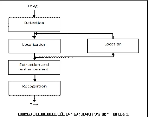
Before defining the steps of the extraction of a text embedded in a complex image, it is important to know the basic properties of texts; geometry, color, movement, edge and compression. In fact, text extraction generates several problems, such as detection, location, identification, extraction, enhancement and recognition. In general, the first three steps can be confused, but in reality they are quite distinct. The detection step determines whether or not texts are present in a given image while localization is a process determining the location of a text in an image and generating frames around the text. This identification is performed to reduce the processing time of localization and memorize the original location of the text in the image. In fact, the extraction turns the text into a binary image by extracting it from the background of the initial support. As a result, the text will be improved to give a better resolution. The recognition process, using the technique of optical character recognition (OCR), transforms the printed text (analog) into a digital file consisting of ASCII characters instead of pixels (analog file). In this context, it is important to note that in our study, we are interested mainly in detecting, locating and extracting the text boxes from the scanned documents and colored images using the Gamma Correction Method (GCM). For instance, in figure 1, we show the basic steps of text extraction from images. Moreover, many related algorithms are used in color image processing, which are usually software implementations. On the other hand, the hardware feature will typically increase the processing speed. Then, through the technology advances in the system integration, we can propose the system design as some functional blocs with at least one processor (as a processing unit). The general idea behind this is to attribute complex computing tasks to the hardware (here FPGA). This attribution helps to exploit the parallelism and pipeline algorithms, and operate the software flexibility, which results in a context of "codesign".
______________________________________
• Anis Boudabous, College of Computer and Information Sciences, Jouf University, Kingdom of Saudi Arabia, and LETI (E.N.I.S.), University of Sfax, Tunisia.
• Mohamed Amine Ben Atitallah, National Engineering School of Gabes, University of Gabes, and A3SI, ESIEE Paris, CNRS, Paris-Est University, France
• Ahmed Ben Atitallah College of Engineering, Jouf University, Kingdom of Saudi Arabia, and LETI (E.N.I.S.), University of Sfax, Tunisia.
6573
Fig. 1. Basics steps for extracting texts from images. In this work, we are interested particularly in the design of a System on Programmable Chip or SOPC using the EP2S60F672C3 FPGA board. We propose in this work a Custom Instructions integrated in our HW/SW system. This implementation will be made to speed up the overall execution time of the algorithm relating to the Gamma Correction Method (GCM). Therefore, this paper is organized as follows: Section II presents the method and theory of Gamma Correction Method (GCM). Section III deals with a preliminary complexity study of GCM. Then, in section IV, we propose a SOPC system based on the NiosII processor. This section also reports on a software implementation and profiling which was performed using the NiosII processor in a SOPC context. In section V, we explain and detail the hardware implementation of contrast and energy. The HW/SW implementation of the Gamma Correction Algorithm using the Altera NiosII development board is the subject of section VI. Finally, the conclusions are drawn in the last section
2 THE
GAMMA
CORRECTION
METHOD
The Gamma Correction Method (GCM) is a well-known technique applied in color images and particularly in text extraction. More precisely, it eliminates the background and focuses mainly on the text region. As a consequence, the correlation between the existing input (x) and output (y) can be represented by the following equation (1):
𝑦 = 𝑥 (1)
Inside the perfect case, γ= 1, the input and output values are the same. Therefore, if the gamma values deflect from ‗1‘, we detect a major intensity difference in the input and output values. While if gamma comes close to zero, the output pixels turn dark. On the other hand, if gamma tends to infinity, the pixels become brighter. In fact, the diagram below, (figure 2), indicates the different stages of GCM designed for text extraction from complex images. We begin by generating the adapted (or modified) image from the original one for the different gamma values (γ =0.1…10) using the following equation:
pm(i) = ((0.5 + (
) ) ∗ GRAYLEVEL − 1) (2)
pm(i): is performed to modify all pixels in the original image and create the adapted or modified image, for each gamma value.
The GRAY LEVEL represents the pixel density. After that, for each image, we define the image threshold by producing four Gray Level Co-occurrence matrixes, GLCM, (for 0, 45, 90 and 135 degrees). In fact, these co-occurrence matrices calculate the occurrence probability P(j, i, δ, θ) of the pair values of pixels situated at some distance within the test image. As for the occurrence probability, it defines the number of times, anywhere, a color intensity i of one pixel appears at a distance equal to 1 (δ = 1) from another pixel with color intensity j. We consider this, along with all the orientation values (θ = 0, 45, 90 and 135 degree). The characteristics extracted from the co-occurrence matrices contain the homogeneity information, the linear dependencies between the gray levels, the contrast and the image complexity. The matrices obtained according to the four directions are calculated as shown below:
𝑃(𝑖, 𝑗, δ, 0) = |{ ((𝑘, 𝑙), (𝑚, 𝑛)) ∈ (𝑁 ∗ 𝑀)
𝑤𝑖𝑡ℎ(𝑘 − 𝑚 = 0, |𝑙 − 𝑛| = δ, I , = 𝑖, l , = 𝑗)}|
𝑃(𝑖, 𝑗, δ, 45) =
|{
((𝑘, 𝑙), (𝑚, 𝑛)) ∈ (𝑁 ∗ 𝑀)
𝑤𝑖𝑡ℎ (𝑘 − 𝑚 = δ, l − n = −δ)⌵(𝑘 − 𝑚 = −δ, l − n = δ), I , = 𝑖, l , = 𝑗
}|
𝑃(𝑖, 𝑗, δ, 90)
= |{ ((𝑘, 𝑙), (𝑚, 𝑛)) ∈ (𝑁 ∗ 𝑀)
𝑤𝑖𝑡ℎ (|𝑘 − 𝑚| = δ, 𝑙 − 𝑛 = 0, I , = 𝑖, l , = 𝑗 )}|
𝑃(𝑖, 𝑗, δ, 135) =
|{
((𝑘, 𝑙), (𝑚, 𝑛)) ∈ (𝑁 ∗ 𝑀)
𝑤𝑖𝑡ℎ (𝑘 − 𝑚 = δ, l − n = δ)⌵(𝑘 − 𝑚 = −δ, l − n = −δ), I , = 𝑖, l , = 𝑗
}|
where:
(k, l) are the coordinates of color intensity i ∈ [0,nmax-1]. (m, n) are the coordinates of color intensity j ∈ [0,nmax-1]. This enabled us to calculate the energy and contrast values [3][4].
6574
2.1 Energy and Contrast
The energy value (E), which is also defined as uniformity or ASM (Angular Second Moment), describes the smoothness of the image. It performs the uniformity of texture which is in fact the pixel pair duplications. The energy is then given by equation (3):
E = ∑ ∑ p(i, j) (3) p(i,j): GLCM pixel
Ng: the maximum of gray level
The contrast (C) estimates the local gray level deviation (equation 4) the value of which indicates the spatial frequency of the image and a diverse moment of GLCM.
C = ∑ n ∑ ∑ ,| | p(i, j) (4) The gray level image will then be transformed into a binary image by means of Otsu‘s technique.
2.2 Otsu’s technique
Roughly speaking, Otsu‘s technique [3] looks for the adequate threshold (denoted by T) that decreases the variance within the class, (the intra-class variance), distinguished as a weighted addition of the two class variances, as described in equation (5):
σ (T) = ω (T)σ (T) + ω (T)σ(T) (5) 𝜎 , 𝜎 : corresponds to the inter-class variance
𝑤: corresponds to the probability to be in classes 1 or 2.
Moreover, Otsu proved that reducing the intra-class variance is a matching concept to capitalize an inter-class variance specified by equation (6):
σ (T) = σ − σ (T) = ω (T)ω (T)[μ (T) − μ (T)] (6)
μ : corresponds to the mean value for separation,
ω1(t) corresponds to the class probability, which is calculated in equation 7 using the image histogram:
ω (T) = ∑ p(i) (7) p(i) : density of the probability,
Where the class mean is μ1(T), as presented in equation (8): μ (T) = (∑ p(i)x(i))/ω (8) x(i) : is a vector from (0) to (maximum of gray level -1) This process will be repeated 100 times (MGLCM, contrast, energy, and threshold) for all the gamma values. After that, we guess the optimum value of Gamma based on the contrast, energy and threshold. Finally, the corrected and the binary images are created. In the next section, we will discuss in details how to deduce the most favorable Gamma value.
2.3 Gamma estimation
To approximate the Gamma value, we apply several rules extracted from paper [3]. This expected value of gamma was applied in the image input to generate a corrected image. In conclusion, Otsu's algorithm was used to evaluate the threshold and apply the value needed to produce the output image. Figure 3 shows a diagram illustrating the GCM rules.
3
PRELIMINARY
STUDY
OF
GCM
Our previous research has focused on the complexity of this efficient algorithm for text extraction from complex images based on the GCM [10]. Initially, our C/C++ algorithm study of gamma correction was made on a personal computer i3, 2 GHz. We
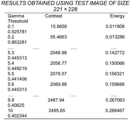
calculated an execution time equal to 2s for an image of 221 × 228 pixels. Then, the performance of our C/C++ algorithm was compared to C code written using the OpenCV library. This later is provided in the framework of cooperation with the computer lab Gaspard Monge, ESIEE Paris. In fact, a comparison between the execution time of our C code and the C code using OpenCV has been cited in the previous work [10]. We therefore obtained an important optimization of the execution time (50%) using our C code. Our code gave the same value of gamma compared to the code using an OpenCV. Finally, the basic purpose was to develop a C/C++ algorithm regardless of the OpenCV library. This new version of this algorithm makes it possible to implement the gamma correction method on an FPGA board in the context of HW/SW design. To validate the Gamma correction algorithm (or Gamma estimation), we used a standard image having a size of 221 × 228 pixels. The implementation of the different stages of the GCM (see figure 2) was determined for each gamma value, contrast, energy and threshold. Table I provides an overview of the values generated using a test image (figure 14 (a1), size 221 × 228 pixels). By means of these results, we can estimate the optimal gamma value using the rules 1, 2 or 3 (see figure 3). Therefore, in the case of the image in figure 14 (a1), Rule 2 has been applied for γ = 1 (original image) then, the energy value is <0.05 and the contrast value> = 1000. This rule helps to resolve the optimum value of gamma (γ = 10) which helps to remove the image background (figure 14 (b1)) and therefore the selection of the threshold value (T = 0.402344) which is used to convert the grayscale image into a binary image (figure 14 (c1))However, in the image presented in figure 14 (a2), Rule 3 has been applied for γ = 1 (original image); where the energy value <0.05 and the contrast value <1000 therefore γ = 6 (figure 14
(b1)), T=0.292969 (figure 14 (c1)). This new version of algorithm can be implemented in a HW/SW design based on ―System on Programmable Chip‖ (SOPC) in order to improve its performance. In the following sections, we will define and discuss the SOPC system design.
4 PROPOSED
SOPC
SYSTEM
BASED
ON
TABLE1
RESULTSOBTAINEDUSINGTESTIMAGEOFSIZE 221×228
Gamma Contrast Energy Threshold
0.1 15.8656 0.011908 0.925781
0.2 55.4663 0.013286 0.863281
…. …. …. ….
5.3 2046.98 0.142772 0.445313
5.4 2056.77 0.150066 0.449219
5.5 2078.57 0.156321 0.441406
5.6 2089.88 0.159688 0.445313
…. …. …. ….
9.9 2487.94 0.267063 0.40625
6575
NIOSII
PROCESSOR
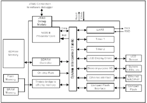
In general, a SOPC or an embedded system is designed to perform one or more functions that are defined in the specifications. For the software part, the C/C++ language is generally used. For the hardware part, the VHDL or the Verilog language are usually operated as they help with description in the RTL (Register Transfer Level). An important stage of validation and testing of the good functionality of the described circuit is then performed. The Quartus II software was proposed by the Altera (actually Intel-FPGA) Company [11] for the complete management of the FPGA design flow. The IDE Quartus II (Integrated Design Entry) integrates a SOPC Builder tool which is used to build the SOPC system besides, this tool integrates various I/O devices such as the NiosII processor, the SRAM and SDRAM controller, a DMA controller (Direct Memory Access). Figure 4 illustrates the different devices connected to the NiosII processor through the Avalon bus for a typical SOPC system [12].
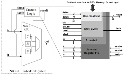
Fig. 4: Typical implementation of a SOPC system Similarly, we can integrate our component in the design as an external IP block (camera interface, VGA, hardware accelerator ...). We can also integrate many devices as many as we like but they are just limited by the number of pins and logic cells of the FPGA. At the final step of the SOPC system, Quartus II generates the project by integrating all IP modules. After making a synthesis, we get the FPGA programming file corresponding to our SOPC design. On the other hand, we have a software development kit that includes the entire C files (.c and .h) to control the peripheral I/O Altera. The co-design advantage appears here, with the opportunity to develop some parts of the design via a hardware or a software. The NIOSII embedded processor is a software firmcore processor which is exclusively devoted to the Altera family. In fact, the embedded software processor NIOSII is configurable and upgradeable, enabling developers to have a flexible and robust SOPC solution. Moreover, the NiosII processor is a totally synchronous RISC processor which has a Harvard internal architecture and a maximum of six pipeline stages with a 32-bit bus width. Its performance is 30 to 80 MIPS (Million Instructions per Second). However, it is possible to accelerate some processes by adding custom instructions to the NIOSII processor, as described in VHDL. In this way, it is possible to realize the operator overload or simply extend the instruction set. From figure 5, it is clear that we can add two types of instruction: Combinatorial (one
cycle) or sequential (multi cycle) [12], to the Arithmetic Logic Unit (ALU) of the NiosII processor. To evaluate the speed performance of the gamma correction algorithm on an embedded design, we have implemented a SOPC system based on the NIOSII embedded processor, which is shown in figure 6. This system consists of the NIOSII processor, the Avalon bus and some devices (memory controller, UART, timer ...). The NIOSII processor is the heart of the system. It is clocked at 100 MHz, and multiplication and division are wired. Moreover, the size of the instruction cache and data is 64KB. This processor is connected to various devices through the Avalon bus. The interface of this bus is automatically generated by an Altera NIOS generation tool (SOPC Builder). This embedded system is implemented on a Stratix II FPGA EP2S60F672C3, which provides 48352 ALUTs, 310 KB of embedded memory, 288 DSP blocs (9bits x 9bits), 6 PLLs and 493 inputs/outputs.
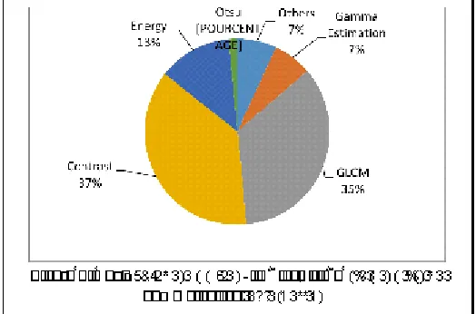
6576 Figure 8 shows the average CPU run-time of the different
blocs of the gamma correction algorithm for some images of 221x228 pixels. We also noticed that complexity is highly located in the three processing blocs: GLCM (35% of CPU time), contrast (37% CPU time) and energy (13% of CPU time).
Fig. 7: The EP2S60F672C3 board
These results allow a first hypothesis on the hardware and software partitioning: blocs to be totally or partially realized in the hardware (hardware IP) and blocs that may be implemented in the software. In fact, for the good equations regularity contrast and energy, they can be implemented in the hardware using the custom instructions of the NiosII processor. Moreover, the GLCM block must be completely wired from its intensive memory access. This block is an excellent candidate for hardware implementation as a co-processor. Finally, the two remaining blocs (Gamma Estimation and Otsu) do not require a lot of resources and are therefore, achieved through the software. In fact, we are limited in this research project to the implementation of the blocs of contrast and energy in the hardware which require 50% of the CPU time.
Figure 8: The average CPU run-time of different blocks of the gamma correction algorithm
5 HARDWARE
IMPLEMENTATION
OF
CONTRAST
AND
ENERGY
In this section, we propose a hardware implementation as a policy of ALU equations of energy and contrast data that are illustrated as follows:
𝑛 𝑦 = (∑ ∑ 𝑝(𝑖, 𝑗)
)
𝑜𝑛𝑡 𝑡 = ( ∑ 𝑛
∑ ∑ 𝑝(𝑖, 𝑗)
,| |
)
Ng : Maximum gray level=256. P(i,j) : the pixels of GLCM. n : (i-j)2
In order to implement the equations of contrast and energy, combinatorial instructions are used. They consist of different I/O signals to communicate with the Arithmetic Logic Unit and the NIOSII processor. The signals, dataa and datab inputs as well as the output result, are implemented using 32 bits. An appropriate declaration and good instancing of contrast and energy instructions give you a good real time connection between the hardware and the software part. The execution and the validation use the SOPC Builder tool. Figures 9 and 10 show the architecture developed for the hardware implementation of the contrast and energy equations, respectively. In fact, we have developed an architecture for the contrast (figure 9) and the calculation of the ((𝑖 − 𝑗) × 𝑃(𝑖, 𝑗)) and ((𝑖 − 𝑗 − 1) × 𝑃(𝑖, 𝑗 + 1)) of two pixels of the matrix GLCM then perform their summation. For this reason, we use in our architecture dataa and datab as two input signals. DataA signal contains the concatenated values of i and j, which are 8 bits each. On the other hand, datab signal contains the concatenated values of P (i, j) and P (i, j + 1). These values are 16 bits each while the final result was obtained by combining 32 bits. The same architecture is applied in the case of energy (figure 10) to calculate 𝑃(𝑖, 𝑗) of two pixels of the matrix GLCM. Indeed, DataA and DataB contain 𝑃(𝑖, 𝑗) and 𝑃(𝑖, 𝑗 + 1), respectively. The final result is obtained by adding them. The implementation
TABLE2
FPGAIMPLEMENTATION RESULTS OF THE PROPOSED SOPC
SYSTEM WITHOUT CUSTOM INSTRUCTIONS Resources Required
ALUTs 4,416/48,352 (9%)
Blocs RAMs 1, (65%) 645,824/2, 544,192
DSPs Blocs 8/288 (7%)
Pins I/O : 126/493 (26%)
PLL 1/6 (17%)
6577 results for the contrast and energy instructions on Stratix II
FPGA EP2S60 are given in table III. These results show a low use of hardware resources on FPGA for the contrast and energy architectures.
Fig. 9: Hardware architecture of the contrast instructions
Fig. 10: Hardware architecture of the energy instructions
TABLE3
HARDWARE IMPLEMENTATION RESULTS OF CONTRAST AND ENERGY
Contrast Energy ALUTs 58 (<1%) 32 (<1%)
I/O 96 (28%) 96 (28%)
Blocs DSPs 6 (6%) 4 (4%)
6 HW/SW
IMPLEMENTATION
OF
THE
GAMMA
CORRECTION
ALGORITHM
In this section, we will evaluate the gamma correction algorithm performance in a HW / SW context. Indeed, the assessment will be made before and after the integration of
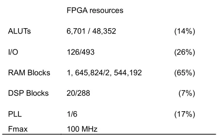
the hardware instructions of the contrast and energy in the ALU of the NIOSII processor as Custom instructions. In fact, figure 11 illustrates the NIOSII embedded system after the integration of the contrast and energy instructions. The results of the implementation of our embedded system NIOSII FPGA II Startix EP2S60 are given in table IV. These results also show that the implementation of various devices constituting this system leaves enough resources in the FPGA to add other IP blocs. The percentage measures and the use rate of the processor, depending on the different processing block gamma correction algorithms, are illustrated in figures 12 and 13. We represent the software solution and the HW / SW solution for an image of size 106 × 160 pixels and 221 × 228 pixels.
Fig. 11: Architecture of the NIOSII embedded system using Custom instructions
TABLE4
HW/SWIMPLEMENTATION RESULTS OF THE NIOSII EMBEDDED SYSTEM USING CUSTOM INSTRUCTIONS
FPGA resources
ALUTs 6,701 / 48,352 (14%)
I/O 126/493 (26%)
RAM Blocks 1, 645,824/2, 544,192 (65%)
DSP Blocks 20/288 (7%)
PLL 1/6 (17%)
Fmax 100 MHz
6578 instructions for the contrast and energy) allowed 35% of
optimization in run time compared to the SW solution. This is true for the image sizes 106 × 160 pixels and 221 × 228 pixels. In conclusion, these two architectures allow a speed gain about 35%. This is due to the halving of the iteration number at the software level. In addition, this is due to the minimization of the complexity of calculation when we apply arithmetic operations in hardware while the contrast and energy instructions have taken only 1% of the FPGA area.
7 CONCLUSION
In this paper, we have proposed an acceleration method of the GCM algorithm based on the HW/SW co-design platform. This implementation is based on an embedded NiosII FPGA board, which is a methodology that takes into account the dependency between GCM components. The obtained results of HW/SW implementation are interesting. Indeed, since the whole run time of the method fell by 35% and preserved the same image quality. In fact, the algorithm was applied to multiple images taken from the ICDAR database. However, this model has a deficiency caused by is due to the memory occupation in the different stages of the GCM. Therefore, the integration of the GLCM helps to ameliorate the hardware implementation opportunity by adding a new IP (intellectual property) in the design. This idea is very interesting not only for our case study, but also for other similar algorithms.
8
ACKNOWLEDGMENT
We would like to thank our colleagues from ESIEE Paris, who provided us with insights and expertise that greatly assisted us to conduct this research work and then, improve it.
REFERENCES
[1]. Sanja Juric , Vedran Klepac ―Gamma and Gamma Correction in Television Production‖ 51st
International Symposium ELMAR-2009,
September 2009, Zadar, Croatia p.p. 28-30 [2]. Xu Guan, Su Jian, Pan Hongda, Zhang Zhiguo,
Gong Haibin,
[3]. ―An Image Enhancement Method Based on Gamma Correction‖ Second IEEE International Symposium on Computational Intelligence and Design, p.p. 60 - 63, 2009
[4]. Jinfang Shi , Yong Cai,―A Novel Image Enhancement Method Using Local Gamma Correction with Three-level Thresholding‖ IEEE 6th International Conference on Information Technology and Artificial Intelligence (ITAIC), p.p. 374 - 378, 2011
[5]. Mahmood Farshbaf Doustar and Hamid Hassanpour, ―A locally-adaptive approach for image gamma correction‖. 10th International Conference on Information Science, Signal Processing and their Applications (ISSPA 2010) pp.73-76
[6]. Ajay Khunteta, D. Ghosh, Ribhu "Fuzzy Rule-based Image Exposure Level Estimation and Adaptive Gamma Correction for Contrast Enhancement in Dark Images" IEEE 11th
International Conference on Signal Processing (ICSP), p.p. 667 - 672, 2012,
[7]. ElHarraj and N. Raissouni ―OCR accuracy improvement on document images through a novel pre-processing approach‖ Signal & Image Processing : An International Journal (SIPIJ) Vol.6, No.4, August 2015
[8]. ChhayaGautam, NeerajTiwari ―Efficient Color Image Contrast Enhancement Using Range Limited Bi-Histogram Equalization With Adaptive Gamma Correction‖ IEEE International Conference on Industrial Instrumentation and Control (ICIC) India. May 28-30,2015
[9]. G.G. Devi and Sumathi C.P. "Text Extraction from Images using Gamma Correction Method and different Text Extraction Methods – A Comparative Analysis" International Conference on Information
Communication and Embedded Systems
(ICICES), 27-28 Feb. 2014
[10]. Sumathi C.P. and G. Gayathri Devi, ―Automatic text extraction from complex colored images using gamma correction method‖ Journal of Computer Science 10 (4), 2014 p.p. 705-715
[11]. Mohamed Amin Ben Atitallah, Anis Boudabous, Ahmed Ben Atitallah and Rostom Kachouri, "Complexity study of the Gamma correction method for text extraction from complex images" 16th International Conference STA 2015 December 21-23, 2015 Monastir, Tunisia
[12]. https://www.altera.com
6579
Fig. 3: The GCM rules
6580 (a)
(b)
(a)
(b)
Fig. 12. CPU runtime using the SW solution (a) and HW/SW (b) using image size 106 × 160 pixels
Fig. 13: CPU runtime using the SW solution (a) and HW/SW (b) using image size 221×228 pixels
(a1) (b1) (c1)
Contrast= 2495.65 , Energy= 0.268467
6581
Fig. 14. (a) original Image (b) gamma correction effect (c) Output image
(a2) (b2) (c2)
Contrast= 745.576 , Energy= 0.00184619
γ=6 T=0.292969
(a3) (b3) (c3)
Contrast= 820.318 , Energy= 0.00102407