Research article
Available online www.ijsrr.org
ISSN: 2279–0543
International Journal of Scientific Research and Reviews
Determination of Hydrodynamic Forces in Rectangular Storage Tanks
under Seismic Action
Michel Faridkhouri
1* and
Wassim Joseph Elias 21
Department of Civil Engineering, Branch II, Lebanese University, Roumieh, Lebanon
2
Research Engineer at Optimal Engineering Consulting & Contracting, Roumieh, Lebanon
ABSTRACT
In designing reinforced concrete rectangular storage tanks, it is important to evaluate the hydrodynamic fluid pressures generated during earthquakes.Codes and investigators suggested procedures to evaluate hydrodynamic effects on rectangular tank structures; the complications of these procedures and the factors involved make them difficult to use. This article provides a simplified method to solve wall forces in rectangular storage tanks subjected to earthquake loading. Comparing the suggested procedure with Housner’s and ACI methods, it is observed that the results of these equations are accurate and reliable. Consequently, a step-by-step procedure that is very useful for structural engineers and designers is presented to evaluate wall forces.
KEYWORDS:
Rectangular tanks, convective component, impulsive component, liquid-containingstorage tanks, zone acceleration factor.
*Corresponding Author:
Michel Farid Khouri
1. INTRODUCTION
To calculate the hydrodynamic forces in liquid-containing tanks during lateral seismic excitation,
a reduced model is used that is composed of a spring-mass system shown in Figure 1 which simulates
the impulsive and convective modes of vibration of a tank-fluid system.
Figure 1.Spring-mass Model.
Under earthquake loading, tank walls and liquid are subjected to horizontal acceleration. In the lower
region of the tank, the liquid behaves like a mass that is rigidly connected to the tank walls. This mass is
termed as impulsive liquid mass which accelerates along with the wall and induces impulsive
hydrodynamic pressure on the tank walls and similarly on the base1. In the upper region of the tank, the
liquid mass undergoes sloshing motion. This mass is termed as convective liquid mass and exerts
convective hydrodynamic pressure on the tank walls and base1.
Consequently, the total liquid mass gets divided into two parts, impulsive mass and convective mass.
In the spring-mass model of the tank-liquid system presented in Figure 1, these two liquid masses are to
be properly represented. The dynamic movement induces impulsive component where the mass
generates pressure and suction; these effects will produce the impulsive force Pi applied at height hi from
the bottom of the tank, whereas the convective pressures on the tank walls will induce the convective
force PC applied at height hC.
The main parameters that affect the response of the liquid containing concrete rectangular tanks
arepresented in Figures 2.a &2.b; these are:
B = Width of the rectangulartank,
L = Half Length of the rectangulartank and
Notice that B is less than L, and if L is less then B a permutation procedure between L and B is adopted
in all the equations.
Figure 2.a Geometry of the Rectangular Tank.
Figure 2.b Geometry of the Rectangular Tank.
Usually, when (L/H) is greater than 0.66,the tank is considered a shallow tanks. If (L/H) is smallerthan
0.66 the tank is considered a deep tank. The authors have treated a similar problem for shallow circular
storage tanks2. On the other hand, for deep tank structures that contain solid material, a different
concept is applied and the tank is treated like a silo3.
2. BACKGROUND
Hydrodynamic forces in liquid storage tanks have been considered by various investigators.
In addition, ACI 350-011 presents a seismic design of liquid containing concrete structures which
contain the seismic zone factor in addition to many other factors that affect the design.The parameters of
the spring mass model depend on tank geometry and were originally derived by Housner6, and used in
the ACI code1.
Similar to ACI1, a comprehensive study was made by NZC 31067; it is based on assuming that
the tank is rigid. Another method generated by TID 70248; it is based on an average velocity response
spectrum.
The above methods are a bit complicated to apply. They suggest equations that require various
data and constants that may be complicated to get and/or apply.
There are many other dimensions to the problem where many investigators have worked in this area
such as Zhou et al.9 who studied the effect of impact loading on liquid tanks as compared to seismic
loading. Also, Sezena et al.10 studied the supporting system using a simplified three-mass model along
with a finite element model. Chen et al.11 on the other hand, proposed a model that considers the effect
of the flexibility of tank walls on hydrodynamic forces, and Ghammaghami et al.12used the finite
element method to study the effect of wall flexibility on the dynamic response using the scaling of
El-Centro earthquake, while Cheng et al.13derived dynamic fluid pressure formulas based on the velocity
potential function of liquid movement.
The objective of this work is to make use of the above models and codes to generate a sequential
system of equations that estimate forces and components needed in the design of rectangular tank walls;
these components are then used to come up with a simplified design method that can be used by
engineers and designers.
3. ANALYSIS
There are various important factors that need to be determined when performing the analysis.
These factors are the impulsive and convective components, frequency of liquid oscillation, wave
amplitude, base shear and moments. These are determined in the following sections.
3.1 Impulsive component
As far as the vibration of the tank walls,our interest is with the first mode which is activated by the impulsive mass of the liquid and the geometry of the tank.
(1)
where the stiffness k and mass m are given by:
(2)
(3)
Ec= modulus of elasticity of concrete (MPA),
tw= average wall thickness (mm),
h = height of the wall (mm),
mw= mass of the tank wall (T), and
mi = impulsive mass of contained liquid of a circular tank (T).
It is assumed that the tank walls are rigid and it is important to note that wall flexibility does not affect
convective pressure distribution, but can have substantial influence on impulsive pressure distribution in
tall tanks.
3.1.1 Equivalent mass
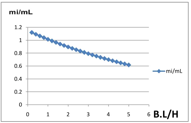
The equation that relates mi/mL to B.L/H is given by:
where, (4)
mL= Total mass of the stored liquid, and
mi= Equivalent mass of the impulsive component stored liquid.
The graph relating mi/mL to BxL/H is presented in Figure 3. Notice that the effect of the impulsive
seismic mass decreases as BxL/H increases. This is due to the fact that when the tank becomes deeper
(BxL/Hdecreases) the fluid in the tank behaves like it is rigidly connected to the tank wall so the fluid
mass mi moves with the tank walls as they respond to the ground motion and the impulsive mass
Figure 3. Equivalent mass of the impulsive component stored liquid versus BxL/H.
3.1.2 Load application level
For the load application levels, formulas (5) and (6) give hi/H with Excluding Base Pressure (EBP) and
Including Base Pressure (IBP) as a function of L/H, respectively.
These equationsare:
(5)
(6)
Figure 4. Height of the impulsive seismic forces versus L/H with H = 1m&az= 0.3.
0 0.2 0.4 0.6 0.8 1 1.2
0 1 2 3 4 5 6
B.L/H
mi/mL
0 0.2 0.4 0.6 0.8 1 1.2
0 0.2 0.4 0.6 0.8 1 1.2
hi/H(EBP)
In Figure 4, an example is presented for H=1m and zone acceleration factoraz=0.3 with variable L shows
the application level of the impulsive component including and excluding base pressure. It increases
with L/H for (IBP) and decreases somewhat for (EBP) due to the reduction of the impulsive mass
relative to the static fluid mass. It is more critical to design the tank wall when excluding base pressure
(EBP).
On the other hand, including base pressure is very significant for the base and foundation design
because it will change the location of the impulsive resultant force and tends to increase with increasing
L/H as presented in Figure 4.
3.1.3 Lateral pressure
During an earthquake, the force Piapplied at hichanges direction several times per second,
corresponding to the change in direction of the base acceleration, this causes the overturning moment
generated by Pi to be basically ineffective in tending to overturn the tank.
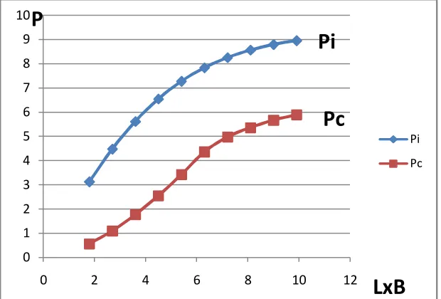
The equation that relates Pi to LxB and H is given in Tons by:
(7)
Pi = Total lateral impulsive force associated with mi
az= Zone acceleration factor,Sezena, H., Livaoglu. et al.
α and β are coefficients that depend on B & H;they are calculated using equations 8 and 9.
(8)
(9)
Where the coefficients , , , and are calculated using equation (10).
Figure 5. Total impulsive and convective forces associated with mi versus L x B with H = 3m&az=0.3.
Figure 5 relates P to LxBwhere the zone acceleration factor istaken equal to 0.3 and H=3m; notice that
the impulsive force and the convective force increases with LxB and the latter curves up higher than the
former which significantly influences the design.
3.2 Convective Component
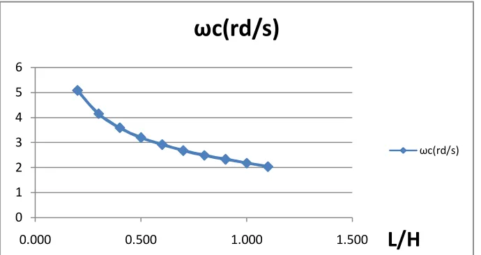
3.2.1 Circular frequency
The circular frequencyωcof the first convective mode in rad/s of the spring-mass system shown
in Figure 1 is given by:
= . ln + (11)
The coefficients a and b of equation (11) are calculated using equation (12).
(12)
0 1 2 3 4 5 6 7 8 9 10
0 2 4 6 8 10 12
Pi
Pc
P
LxB
Pc
Figure 6.Circular frequency of oscillation of the first convective mode versus L/H.
Figure 6shows thatωc decreases as L/H increases so that the wave oscillation tends to be slower as L/H
increases.
3.2.2 Equivalent mass
The convective pressures on the tank walls with resultant force Pc that acts at a height hc above
the tank bottom is produced by the equivalent mass mCof the oscillating fluid. In the model, the force Pc
fluctuates sinusoidally with a period of vibration that depends on the dimensions of the tank and can be
several seconds or longer. The mass mc is considered to be fastened to the tank walls by springs that
produce a period of vibration corresponding to the period of the vibrating liquid as presented in Figure 1.
The equation that relates mc/mL to R/H is given by:
(13)
A graph relating mC/mL to BxL/H is presented in Figure 7. Notice the convective seismic mass
increases with BxL/H opposite to what is shown in Figure 3 where the impulsive seismic mass decreases
with BxL/H. This is due to the geometry of the tank, when the tank becomes shallower (BxL/H
increases), the fluid in the tank becomes less connected to the tank walls so the fluid will oscillate easily
and the convective mass controls the forces.
0 1 2 3 4 5 6
0.000 0.500 1.000 1.500
ωc(rd/s)
ωc(rd/s)
Figure 7. Equivalent mass of the convective component stored liquid versus B.L/H.
3.2.3 Load application level
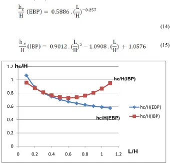
The equations that relate hc/Hto (L/H) are:
(14)
(15)
Figure 8.Height of the applied convective seismic forces versus L/H.
0 0.05 0.1 0.15 0.2 0.25 0.3 0.35 0.4 0.45
0 1 2 3 4 5 6
mc/mL
mc/mL
0 0.2 0.4 0.6 0.8 1 1.2
0 0.2 0.4 0.6 0.8 1 1.2
hc/H(EBP)
Figure 8 shows the application level of the impulsive component including and excluding the base
pressure.Notice that hc/H(EBP) decreases with L/H while hc/H(IBP) behaves in a parabolic manner
decreasing with L/H (minimum about L/H=0.66) and then increasing as L/H increases. This is because
when including base pressure, the rectangular tank is considered as a rigid and stiff structure when L/H
is too small so that the impulsive mass mi controls the design while the convective mass generates a
bending moment on the rectangular tank walls different to the behavior seen in circular walls tank,
Khouri, M. F. et al, where the internal circular walls forces are axial loads; that is why hc/H curve
decreases while L/H increases. Notice that when the value of L/H becomes greater than 0.66, the height
hc of the convective force begins to increase while L/H increases as a result of the oscillating convective
mass mc.
3.2.4 Lateral pressure
The total lateral convective forcePcthat is associated with mccan be represented as a function of
LxB and H as follows:
(16)
where Pc is in Tons, and the coefficients γ and δthat depend on H and B are given as follows:
(17)
(18)
In plotting P versus BxLfor the convective force, a pattern similar to the pattern shown in Figure 5 can
be observed.
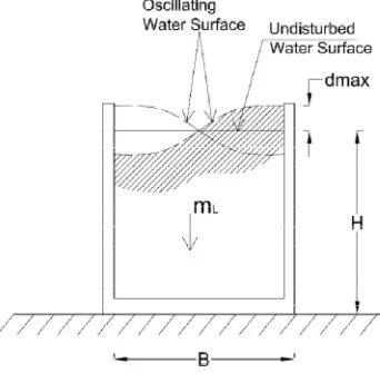
3.3 Wave oscillation
The contained fluid vibrates to a maximum amplitude dmax above the rest fluid flat surface level when
subjected to horizontal earthquake acceleration. In order not to allow any over spills during
earthquakes,this amplitude should stay below the unfilled free height of the tank.
Figure 9.Maximum wave amplitude.
The maximum wave amplitude dmax shown in Figure 9 due to the earthquake acceleration is
calculated in meter using the following equation:
(20)
The coefficients c,d and e are calculated using the following equations:
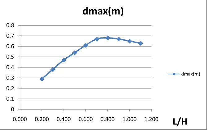
Figure 10.Maximum wave amplitude in terms of (L/H).
A graph relating dmax to L/H is presented in Figure 10, where the wave oscillation increases as
L/H increases from 0.2 to 0.80; when L/H passes the value of 0.80 the wave oscillation decreases due to
the fact that as the length of the tank increases, the wave is dampened due to the longer travel distance
which will decrease the amplitude of the oscillating wave.
3.4 Base shear and moment
The base shear V of the seismic forces, due to liquid effects applied at the bottom of the tank
wall, shall be determined by combining the base shear in impulsive and convective modes by Square
Root of Sum of Squares (SRSS) and is given in Tons as follows:
(22)
Vi = Pi = Base shear in impulsive mode (23)
Vc = Pc = Base shear in convective mode (24)
The base bending moment on the entire tank cross section M just above the base of the tank wall
excluding base pressure shall be determined by combining the base moment in impulsive and convective
mode; it is given in Ton-meter as follows:
0 0.1 0.2 0.3 0.4 0.5 0.6 0.7 0.8
0.000 0.200 0.400 0.600 0.800 1.000 1.200
dmax(m)
dmax(m)
(25)
Mi = Pi x hi(EBP) (26)
Mc = Pc x hc(EBP) ` (27)
The overturning moment at the base of the tank M* just above the base of the tank wall shall be
determined by combining the base moment in impulsive and convective modes (IBP) is given in
Ton-meter as follows:
(28) Mi
*
= Pi x hi(IBP) (29)
Mc *
= Pcx hc(IBP) (30)
4. DESIGN PROCEDURE
Given rectangular storage tank with L/H ratio the tank is to contain a certain fluid volume along
with a zone acceleration factoraz, a design procedure would look as follow:
Step 1:Find the impulsive force Pi and the corresponding application positions (EBP) and (IBP) from
the eq (7), eq (5) and eq(6) respectively after finding the coefficients from the eq (10), eq (8) and eq (9)
respectively.
Step 2: Find the convective force Pc and the corresponding application positions (EBP) and (IBP) from
the eq (16), eq (14) and eq (15) respectively after finding the coefficients from the eq (19), eq (17) and
eq (18) respectively.
Step 3: To design the tank wall against the bending moment, find the base moments in impulsive and convective modes (EBP) from eq (26) and eq (27) respectively, and then calculate the base bending
moment M just above the base of the tank wall using eq (25).
Step 4: Find the base moments in impulsive and convective modes (IBP) from eq (29) and eq (30) respectively, and then calculate the overturning moment M* just above the base of the tank using eq
(28).
Step 5: To calculate the base shear, find the shear in impulsive and convective modes from eq (23) and eq (24) respectively, and then calculate the base shear due to seismic forces using eq (22).
amplitude for a given site zone acceleration factor as, use eq (20) after finding the coefficients from the
eq (21).
Notice that the force pressures applied on dimension B of the rectangular tank walls
perpendicular to the direction of the earthquake are calculated using the above design procedure, while
the force pressures applied on dimension L are calculated using the same design procedure with
permuting B with L and vice versa during the calculations.
5. COMPARISON
Table 1.Comparison of the results obtained from the suggested equations with ACI and Housner.
Dimensions Codes Housner ACI 350-01 Khouri& Elias
B = 3 m H = 4 m L = 4 m az = 0.2
Impulsive Force
Pi = 10.76 (T) Pi = 10.40 (T) Pi = 8.36 (T)
Convective Force
Pc = 4.59 (T) Pc = 5.04 (T) Pc = 6.32 (T)
Convective
Circular Frequency ωc= 2.05 (rd/s) ωc= 1.89 (rd/s) ωc= 1.77 (rd/s)
Maximum wave
amplitude dmax= 1.13 (m) dmax= 0.43 (m) dmax= 0.65 (m)
B = 4 m H = 4 m L = 3 m az = 0.3
Impulsive Force
Pi = 16.15 (T) Pi = 15.61 (T) Pi = 12.54 (T)
Convective Force
Pc = 7.45 (T) Pc = 7.56 (T) Pc = 9.48 (T)
Convective
Circular Frequency ωc= 2.05 (rd/s) ωc= 1.89 (rd/s) ωc= 1.77 (rd/s)
Maximum wave
amplitude dmax= 1.13 (m) dmax= 0.65 (m) dmax= 0.98 (m)
B = 4 m H = 6 m L = 8 m az = 0.2
Impulsive Force Pi = 33.80 (T) Pi = 27.25 (T) Pi = 22.40 (T)
Convective Force
Pc = 8.58 (T) Pc = 7.69 (T) Pc = 8.51 (T)
Convective
Circular Frequency ωc= 1.61 (rd/s) ωc= 1.27 (rd/s) ωc= 1.17 (rd/s)
Table 1 shows an example that compares the values of the impulsiveseismic force, convective
seismic force,convective circular frequency and maximum wave amplitudeusing different codes. Various
dimensions for shallow tanks and zone acceleration factors are analyzed using the suggested equations
in this article and compared to the method presented by ACI and Housner. It can be observed that the
valuesare very close for similar tank dimensions and Zone acceleration factor.
It is important to realize the simplicity of the application of the equations as well as the design procedure
which can be used by engineers and designers of liquid containing storage tanks.
6. CONCLUSION
In analyzing rectangular tanks, it is important to observe the length to height ratio (L/H). For
L/H<0.66 the rectangular tank behaves like deep tank that vibrates like a cantilever beam with impulsive
components controlling the movement taking into consideration that B is always less than L.
On the other hand, if L/H>0.66, the tank is treated as shallow tank and controlled by convective
components action.
The impulsive pressures are generated by the seismic accelerations of the tank walls so that the force Piis
applied as a pressure force on the wall accelerating the fluid into the wall, and a suction force
accelerating the fluid away from the wall. During an earthquake, the force Pi changes direction several
times per second, corresponding to a change in the direction of the base acceleration; this causes the
overturning moment generated by Pi to be basically in-effective in tending to overturn the tank.
In evaluating the equations presented above for rectangular tanks, the behavior can be summarized by
the fact that seismic forces dominate the design of liquid tanks. Also seismic forces are affected by two
main components which are the dimensions of the tank and the zone acceleration factor az.
Moreover, the results obtained by the suggested equations match very well with those obtained using
Housner and ACI350 in any seismic zone.
Finally, the simplicity of the equations in this design procedure make them very easy to use or program
by engineers and designers who are working in this field.
ACKOWLEDGEMENTS
The authors thank Optimal Engineering Consulting and Contracting, (OECC) who sponsored the major
part of this work, and special thanks to the Lebanese University, Faculty of Engineering, Branch II for
REFERENCES
1. ACI 350.3.Seismic design of liquid containing concrete structures, American Concrete Institute,
Michigan; 2001.
2. Khouri, M. F. and Elias, W. J., On the Evaluation of Hydrodynamic Forces in Shallow Circular
Storage Tanks due to Seismic Action, AES Technical Reviews, Part C, International Journal of
Advances and Trends in Engineering Materials and their Applications (IJATEMA), Ottawa;
2012; 1 (1):73-80,
3. Khouri, M. F., Analysis of Silo Walls without Friction, AES Technical Reviews, Part B,
International Journal of Advances in Mechanics and Applications of industrial Materials
(IJAMAIM) Ottawa., 2010; 1 (1): 69-79.
4. Haroun, M. A. and Housner G. W., Seismic design of liquid storage tanks, Journal of Technical
Councils of ASCE, 1984; 107( TC1): 191-207.
5. NSF Report, Earthquake design criteria for water supply and wastewater systems.NSF Report on
Environmental Quality Systems Inc., Maryland; 1980.
6. Housner, G. W., b., The dynamic behavior water tanks, Bulletin of Seismological Society of
America, 1963; 53(2): 381-387.
7. New Zealand Standard, Code of practice for concrete structures for storage of liquids. NZS
3106:1986, New Zealand; 1986.
8. TID-7024, Nuclear reactors and earthquakes, Prepared by Lockhead Aircraft Corp. and Holmes
and Nurver, Inc. U.S. Atomic Energy Commission; 1963.
9. Zhou, Y. and Zhou, L., Studying of Dynamic behavior of water in a vibrating tank, Journal of
Testing and Evaluation (JTE), ID: JTE01736, Penselvania; 2009.
10.Sezena, H., Livaoglu, R. and Dogangun, A., Dynamic analysis and seismic performance
evaluation of above-ground liquid-containing tanks, Engineering Structures, Elsevier, 2008; 30:
794-803.
11.Chen, J.Z., Ghaemmaghami, A.R. and Kianoush, M.R., Dynamic analysis of concrete rectangular
liquid storage tanks, The 14th Conference on Earthquake Engineering, 12-17 October, Beijing,
China; 2008.
12.Ghaemmaghami, A.R. and Kianoush, M.R., Effect of wall flexibility on dynamic response of
13.Cheng, X.S. and Du Y.F., The dynamic fluid pressure of reinforced concrete rectangular