International Journal of Advanced Engineering, Management and Science (IJAEMS) [Vol-2, Issue-8, Aug- 2016] Infogain Publication (Infogainpublication.com) ISSN : 2454-1311
www.ijaems.com Page | 1372
A Study Regarding the Impact of RF Repeaters
on Cellular Networks
Georgian Grigore
1Faculty of Electronics, Telecommunication & Information Technology, “Gheorghe Asachi” Technical University of Iasi, Bd. Carol I, no. 11, Iasi,700506, Romania
Abstract— Lately, the development of mobile communications connected with the exponential growth of social media applications and their usage imposed in the telecom market an acute need for coverage and services. Due to objective or subjective reasons, in some areas it might be possible to have a lack of coverage with signal or services. Since the price of electronic equipments
capable of enhancing the coverage decreased
dramatically, the end-users can acquire a RF repeater in order to improve the coverage of the network in a specific area. Even though at a first sight, introducing RF repeaters in the mobile networks looks benefical, looking in more detail it can be observed that the draw-backs are bigger, due to the fact that they can introduce interferences in the networks. This study tries to evaluate the impact of a RF repeater over a cellular network (GSM and WCDMA), through simulations in SEAMCAT©.
Keywords— GSM, RF repeater, SEAMCAT, WCDMA.
I. INTRODUCTION
The use of mobile devices has become lately a routine in personal and business life. The market’s “explosion” of very performant and various kind of devices, connected with the exponential growth of social media applications [1] and the roll out of high-speed mobile technologies [2] has made their use widespread, and not only for voice and text applications. Whilst mobile coverage has always been incomplete, expectations have risen and dissatisfaction (which is a subjective issue) with poor coverage/low throughput has grown.
So, in a short, as mobile devices are used more and more so the impact of gaps in coverage are felt more acutely by the user.
In the last years, the development of mobile networks is allowed under technological neutral condition. This means that National Regulator Authority, after allocating a specific frequency band to an operator for mobile communication services, does not impose the use of a specific technology (e.g. 2G, 3G or 4G) in that band. Under this approach, network operator is free to deploy the network according to his economic strategy, but in the same time according to the local market power and needs.
There are also technical reasons why the certain areas areas has a lack of coverage. The walls of buildings, metallisation of windows for thermal reasons, and the use of underground spaces are some of those reasons. The attenuation of the signal caused by the above mentioned reasons will lead to a reduction of throughput in 3G and 4G systems, and to a loss of connection in all systems in the worst case scenario.
In order to encrease the coverage or the capacity of the network, there are 2 possibilities: to install a pico-cell or to install a RF repeater. A pico-cell is a small, low power version of a conventional mobile phone base station to give fill-in coverage in a limited area, thus beeing more expensive than a RF repeater, which just picks up a signal from the base station, amplifies and re-transmits it in the area of poor coverage (similarly it amplifies and re-transmits the signal from a mobile in the affected area to the base station).
Pico-cells are always operated under the direct control of the mobile operator, while RF repeaters are not, thus transforming them into a source of interference to the other users. The problem is that the wideband noise transmitted by the high gain amplifiers used in a repeater can desensitise a base station where the repeater and the base station are within a few hundred metres of each other. Given the number of cellular base stations which can be affected, there is a large area where we can face the degradation of coverage for other users.
So, even though at a first sight, introducing RF repeaters in the mobile networks looks benefical, looking in more detail it can be observed that the draw-backs are bigger, due to the fact that they can introduce interferences in the network.
The aim of this paper is to evaluate the level of the interferences introduced by the RF repeaters in cellular networks.
International Journal of Advanced Engineering, Management and Science (IJAEMS) [Vol-2, Issue-8, Aug- 2016] Infogain Publication (Infogainpublication.com) ISSN : 2454-1311
www.ijaems.com Page | 1373 These gains extend from simply reducing downlink
power usage per user, to enhancing the achieved MCS, to further improving MIMO gains under LOS conditions. For today’s cellular systems, properly deployed repeaters offer an efficient and low-cost solution for both coverage and capacity problems.
The main effect of repeater is to enhance the SINR of an area, which it achieves in the following ways:
• If an area originally does not have sufficient signal (“coverage hole” or “dead spot”), the result of adding a repeater will be hole-filling, or coverage extension. • If an area has signals from multiple BSs without a dominant server (known as “pilot pollution” or the “no dominant server” problem), adding a repeater will create a dominant server (by boosting the SINR of the dominant server while suppressing the SINR of others).
• For 4G systems with MIMO, repeaters can create artificial multipath which enhances MIMO gain under LOS conditions.
All the above enumerated enhancements can be achieved if the repeaters are operated under the direct control of the mobile operator. Otherwise, in the case that the repeaters are deployed outside the direct control of the mobile operator, they will became a source of interference to the other users.
The problem is that the wideband noise transmitted by the high gain amplifiers used in a repeater can desensitise a base station where the repeater and the base station are within a few hundred metres of each other. Taking into account the number of base stations which can be affected, there will be a large area where we can face the degradation of QoS KPI’s.
The most common type of repeater which can cause interference is the one which takes the signals from an entire frequency band, amplifies and retransmits them. Signal strengths and noise levels across the whole band will be increased, and since the frequency band for mobile communications is allocated/shared between different operators, this means that all networks operating in that frequency band are affected. Besides that, the signal levels obtained from the repeater are not planned in the way that they are with a pico-cell. This means that what was intended to be a fix for the coverage problem for a small number of users can result in degrading of QoS for a much larger number of users.
The degradation of QoS will commence to appear because a repeater will contribute in increasing the noise floor both on uplink and downlink, in some cases will block the base station due to overloading and will be a source of oscillations and spurious emissions.
One of the limiting factors in any radio system is the level of electronic noise. This is generated in any circuit by basic physical effects. The noise is “white” at all
frequencies of interest i.e. its power is constant with frequency and proportional to the bandwidth being measured.
In the case of a repeater, the noise at the input is amplified along with the wanted signal. The amplifier itself also adds some noise. The internal noise is usually quoted as the Noise Figure, which is the ratio of SNR at the input to SNR at the output, expressed in dB.
Assuming there are no external noise sources, the thermal noise power at the input, Pin, is given by:
= (1) where k is Boltzmann’s constant, T is the absolute temperature and B is the bandwidth.
At room temperatures this gives a power of -174dBm/Hz. The bandwidth is expressed in dB as
= 10 log (2)
This is then amplified by the gain, G, and the amplifier’s noise figure, NF, is added.
The noise power at the output, Pout, is given by:
= −174 + + + (3)
A normal repeater will have a noise figure of around 6dB average at maximum gain, and a gain of 60dB in the uplink. In the GSM receiver case, which has a bandwidth of 200 kHz ( 53dBHz), the output noise power using the formula deducted above is:
Pout= -174+53+60+6 dBm= -55 dBm (4) According to ETSI technical specification [3], the reference sensitivity of a GSM base station is -104dBm. The noise power from the repeater, as seen by the base station, will be above this limit if the path loss between the repeater and base station is less than 49dB.
So, if there is a relatively small path loss from the repeater to the base station, the noise transmitted by the repeater can be above the sensitivity level of the base station’s receiver, leading to a reduced effective sensitivity of the base station. The manifestation of such a phenomena is reflected in the increased number of lost uplink connections (dropped or blocked calls), especially with the mobiles at the edge of the cell (those mobiles are operating on the upper end of their power control range). The mobile is at the cell edge so the interference mostly affects mobiles that are some distance away from the repeater.
International Journal of Advanced Engineering, Management and Science (IJAEMS) [Vol-2, Issue-8, Aug- 2016] Infogain Publication (Infogainpublication.com) ISSN : 2454-1311
www.ijaems.com Page | 1374 in the cell.
Taking into account those mentioned above, we can identify two cases of interference: inter-network interference and intra-network interference.
In the case of internal network interference, this situation may appear when the outdoor coverage is good but there is a high penetration loss to the user’s location.In these cases the wanted base station may be quite close to the repeater, and so is affected by the raised noise floor. This reduces the coverage area for other mobiles that are on the same cell but outside the repeater’s coverage.
In the case of inter-network interference, this situation may appear when the user is in a poor coverage area for their network operator, but a good coverage area for another operator. In this case, the second operator’s base station will be interfered by the repeater. Thus the affected mobiles are not only distant from the repeater but on a different network to the repeater user.
Another effect caused by interference caused by the repeater is the blocking of base station, due to the fact that the repeater will transmit the signal from the mobile after amplifying it. If the repeater is near to a base station and is working at full gain, then the signal at the input of the base station’s receiver will be at a very high level. This will lead to the overload of the receiver, so the reception of other mobiles will be degraded or stopped entirely. This kind of interference will affect especially UMTS base stations, due to the use of code division multiple access (CDMA). The base station measures the signal level that it is receiving from a mobile and continuously instructs the mobile to increase or decrease its transmitter power. This maintains the signal level at the base station at its optimum level. An increase in the path loss to the mobile will result in the mobile being instructed to raise its power, until it is at maximum power. Any further increase in path loss will cause the mobile to go out of coverage.
A simplified scheme of a repeater will contain two amplifiers, one for the uplink and one for the downlink, connected through a diplexer in order to permit the use of the same antenna. The main signal path for the downlink is from the base station to one antenna, through the downlink amplifier, and from the second antenna to the mobile. The reverse path applies to the uplink.
However there is another path, unintended, the path between the two antennas. This acts as a feedback path from the output to the input of each amplifier. In the case where the loss on the feedback path is less than the gain through the repeater, the repeater will oscillate in the operating frequency band and will be at the repeater’s saturated output power. This will make the repeater to act as a jammer on a base station or mobile.
A similar effect is that of spurious emissions. These are
signals that are generated internally within the repeater from various sources. Even though they could be at any frequency, those within the operating band will be amplified and will introduce a high level of interference.
III. SIMULATION SCENARIOS AND RESULTS The goal of this paper is to try to evaluate the impact of a repeater on different types of mobile networks e.g. GSM, UMTS or LTE. In order to realyse that, SEAMCAT© [4] tool was used.
SEAMCAT© [4] is a software based on Monte-Carlo statistical method, for performing sharing and compatibility studies. It is used in many ECC and CEPT Reports, in the same time beeing a reference tool recognised at ITU, having been ment also as an educating tool for new spectrum engineers for their use in administrations, industry or at Universities.
SEAMCAT© [4] is designed for co-existence studies between different radio systems operating in the same or adjacent frequency bands and is intended mainly (but not exclusively) for systems operating under terrestrial services. One of its advantages is that can be extended to cellular systems based on CDMA and OFDMA technologies. The outcome of this software is mainly the quantification of probability of interference between radio systems.
3.1 Scenario 1- GSM repeater vs GSM network
In order to simulate in SEAMCAT© [4] this case, we supposed that we have only one repeater, defined as a “generic system” single GSM channel transmitter, having also a wideband noise floor.
Repeater’s parameters used in setting up the simulation are presented in TABLE 1.
Table 1
Parameter Value
Emission Power +18 dBm Antenna Gain 0 dBi Frequency 940 MHz
International Journal of Advanced Engineering, Management and Science (IJAEMS) Infogain Publication (Infogainpublication.com
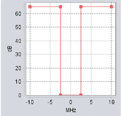
www.ijaems.com Fig.1: Repeater spectrum emission mask
For the GSM base station, parameters used in are presented in TABLE 2.
Table 2
Parameter Value
Noise Floor -110 dBm Sensitivity -104 dBm Reception Bandwidth 200 kHz Receiver Noise Figure 4 dB
C/I 9 dB
C/(I+N) 6 dB
Cell Radius 15 km Operation Frequency 940 MHz Mobile Antenna Height 1.5m Mobile Antenna Gain 0dB Base Station Antenna Height 30m Base Station Antenna Gain 15 dBi
Receiver blocking mask used for GSM bas presented in Fig. 2.
International Journal of Advanced Engineering, Management and Science (IJAEMS) publication.com)
Repeater spectrum emission mask
For the GSM base station, parameters used in simulation
Value 110 dBm
dBm 200 kHz
15 km 940 MHz
15 dBi
Receiver blocking mask used for GSM base station is
Fig. 2: GSM receiver blocking mask
Emission floor, coresponding to the wideband noise generated by the repeater, was set to
order to evaluate the effect of the noise introduced by the repeater in GSM network.
Simulation was repeated for different distances between repeater and GSM base station, using initialy Extended Hata propagation model, in an urban outdoor environment.
The results are presented in TABLE 3. Table 3 Distance (m)
100 200
500
1000
1500
2000
2500
3000
4000
5000
Comparison between desired signal (dRSS vector) and interference signal (iRSS vector), for a distance of 100 meters between repeater and GSM base station presented in Fig. 3.
[Vol-2, Issue-8, Aug- 2016] ISSN : 2454-1311
Page | 1375 GSM receiver blocking mask
coresponding to the wideband noise generated by the repeater, was set to -41dBm/100Hz in order to evaluate the effect of the noise introduced by the
Simulation was repeated for different distances between tion, using initialy Extended-Hata propagation model, in an urban outdoor
The results are presented in TABLE 3. Table 3
Probability of interference (%)
63.6 49.88
25.14
7.79
2.76
1.33
0.62
0.34
0.11
0.01
International Journal of Advanced Engineering, Management and Science (IJAEMS) Infogain Publication (Infogainpublication.com
www.ijaems.com Fig.3: dRSS vs. iRSS, 100 m separation,
For a distance of 5 kilometers between repeater and GSM base station, the comparison can be found in Fig. 4
Fig.4: dRSS vs. iRSS, 5000 m separation, urban outdoor
Then, simulation was repeated for different distances between repeater and GSM base station, using Extended Hata propagation model, in an rural outdoor environment. The results are presented in TABLE 4.
Table 4
Distance (m) Probability of interference (%) 100
200
500
1000
1500
2000
2500
3000
4000
5000
6000
7000
8000
International Journal of Advanced Engineering, Management and Science (IJAEMS) publication.com)
urban outdoor
For a distance of 5 kilometers between repeater and GSM base station, the comparison can be found in Fig. 4.
dRSS vs. iRSS, 5000 m separation, urban outdoor
Then, simulation was repeated for different distances and GSM base station, using Extended-Hata propagation model, in an rural outdoor environment.
Probability of interference (%)
63.38
49.15
29.06
15.55
10.47
7.59
5.35
4.5
3.13
2.16
1.45
1.18
1.01
10000
15000
Comparison between desired signal (dRSS vector) and interference signal (iRSS vector), for a distance of 100 meters between repeater and GSM base station is presented in Fig.5.
Fig. 5: dRSS vs. iRSS, 100 m separation, rural outdoor
For a distance of 5 kilometers between repeater and GSM base station, the comparison can be found in Fig. 6.
Fig. 6: dRSS vs. iRSS, 5000 m separation, rural outdoor
For a distance of 15 kilometers between repeater and GSM base station, the comparison can be found in Fig.
Fig.7: dRSS vs. iRSS, 15000 m separation, rural outdoor [Vol-2, Issue-8, Aug- 2016] ISSN : 2454-1311
Page | 1376 0.58
0.3
Comparison between desired signal (dRSS vector) and interference signal (iRSS vector), for a distance of 100 meters between repeater and GSM base station is
dRSS vs. iRSS, 100 m separation, rural outdoor
For a distance of 5 kilometers between repeater and GSM base station, the comparison can be found in Fig. 6.
dRSS vs. iRSS, 5000 m separation, rural outdoor
distance of 15 kilometers between repeater and parison can be found in Fig.7.
International Journal of Advanced Engineering, Management and Science (IJAEMS) Infogain Publication (Infogainpublication.com
www.ijaems.com It can be concluded from the figures obtained that in the
case of urban environment, the probability that a repeater will affect the GSM network is below 1% if it is placed at a distance higher than 2 kilometers.
In the case of rural environment, the distance must be higher than 8 kilometers.
3.2 Scenario 2- GSM repeater vs WCDMA network In order to simulate in SEAMCAT© [4] this scenario, we supposed that we have only one repeater, defined as a “generic system” single GSM channel transmitter, having also a wideband noise floor.
Repeater’s parameters used in setting up the simulation are presented in TABLE 1, and emission mask from Fig.1.
For the WCDMA network simulation, the parameters from TABLE 5 were used.
Table 5
Parameter Value
Receiver Noise Figure 4 dB Handover Margin 3 dB Call drop threshold 3 dB Voice bit rate 12.2 kbps Reference bandwidth 3.84 MHz Minimum coupling loss 30 dB Users per base station 20 Cell radius 15 km Mobile antenna height 1.5 m Mobile antenna gain 0 dBi Base station antenna height 30 m Base station atenna gain 15 dBi
Frequency 940 MHz
Receiver blocking mask used for WCDMA base station is presented in Fig. 8.
Fig.8: WCDMA receiver blocking mask
Simulation was repeated for different distances between repeater and WCDMA base station, using initialy
International Journal of Advanced Engineering, Management and Science (IJAEMS) publication.com)
It can be concluded from the figures obtained that in the
probability that a repeater will affect the GSM network is below 1% if it is placed at
In the case of rural environment, the distance must be
GSM repeater vs WCDMA network this scenario, we supposed that we have only one repeater, defined as a “generic system” single GSM channel transmitter, having
Repeater’s parameters used in setting up the simulation ented in TABLE 1, and emission mask from
For the WCDMA network simulation, the parameters
blocking mask used for WCDMA base station is
WCDMA receiver blocking mask
Simulation was repeated for different distances between repeater and WCDMA base station, using initialy
Extended-Hata propagation model, in an environment.
The results are presented in TABLE 6. Table 6 Distance (m) 100 500 1000 2000 5000 10000 15000
Then, simulation was repeated for different distances between repeater and GSM base station, using Extended Hata propagation model, in an rural outdoor environment. The results are presented in TABLE 7.
Table 7 Distance (m) 100 500 1000 2000 5000 10000 15000
It can be seen that the capacity loss of the WCDMA system is varying around 20%, no matter what propagation model environment
IV. CONCLUSION
Regarding the effect of repeater on a GSM network, the following conclusions can be extracted from the simulations:
- In the case of an urban deployment of the network, in order to avoid interferences or to bring them to a level which is tolerable, a separation distance of minimum 2 kilometers needs to be taken onto account.
- In the case of rural deployment, the distance must be increased to 8 kilometers.
- All the above mentioned distances are valid if we consider a level of 1% for probability of interference. In case that a lower level of probability of interference is desired, those d
increased.
Regarding the effect of the
network, the following conclusions can be extracted from the simulations:
- No matter what the deployment scenario is, the average system capacity loss is varying from aprox. [Vol-2, Issue-8, Aug- 2016] ISSN : 2454-1311
Page | 1377 Hata propagation model, in an urban outdoor
The results are presented in TABLE 6. Table 6
Average system capacity loss (%) 20.86 21.69 21.15 21.16 19.97 20.6 28.04
Then, simulation was repeated for different distances between repeater and GSM base station, using Extended-Hata propagation model, in an rural outdoor environment. The results are presented in TABLE 7.
Table 7
Average system capacity loss (%) 28.02 20.93 20.84 20.91 21.13 20.92 27.7
It can be seen that the capacity loss of the WCDMA system is varying around 20%, no matter what
environment was used.
CONCLUSION
Regarding the effect of repeater on a GSM network, the can be extracted from the
In the case of an urban deployment of the network, in order to avoid interferences or to bring them to a level which is tolerable, a separation distance of minimum 2 kilometers needs to be taken onto
ase of rural deployment, the distance must be increased to 8 kilometers.
All the above mentioned distances are valid if we consider a level of 1% for probability of interference. In case that a lower level of probability of interference is desired, those distances has to be
the repeater on a WCDMA network, the following conclusions can be extracted from
International Journal of Advanced Engineering, Management and Science (IJAEMS) [Vol-2, Issue-8, Aug- 2016] Infogain Publication (Infogainpublication.com) ISSN : 2454-1311
www.ijaems.com Page | 1378 28% to aprox. 19.97%.
- The impact of the repeater is much higher in WCDMA networks than in GSM networks.
In order to avoid the appearance of such unwanted phenomena, or to reduce the risk of interference in cellular networks, it is becoming clear that at least a combination of the following mesures has to be taken:
- the usage of pico-cells instead of repeaters;
- the usage of repeaters provided by network operators, repeaters which casn be programmed on specific frequencies;
- Obtaining the consent of network operator before putting the repeater into operation;
- Registering the repeater with the network operator before putting the repeater into operation;
- The usage of antennas and cables approved for use with that repeater.
Those measures can be imposed by National Regulatory Authority, in order to reduce the number of interference cases.
REFERENCES
[1] http://www.statista.com/statistics/278414/number-of-worldwide-social-network-users/
[2]
http://www.itu.int/en/ITU-D/Statistics/Documents/statistics/2016/ITU_Key_20 05-2016_ICT_data.xls
[3] http://www.etsi.org/deliver/etsi_gts/05/0505/05.00.00 _60/gsmts_0505v050000p.pdf