CIRCULAR ARRAY TECHNIQUES
FOR SONAR APPLICATIONS
BY
RON E IG ES
A thesis submitted to the University of London for the Degree of
Doctor of Philosophy in Electronic Engineering
Department o f Electronic and Electrical Engineering
U niversity C ollege London
ProQuest Number: 10018515
All rights reserved
INFORMATION TO ALL USERS
The quality of this reproduction is dependent upon the quality of the copy submitted.
In the unlikely event that the author did not send a complete manuscript
and there are missing pages, th ese will be noted. Also, if material had to be removed, a note will indicate the deletion.
uest.
ProQuest 10018515
Published by ProQuest LLC(2016). Copyright of the Dissertation is held by the Author.
All rights reserved.
This work is protected against unauthorized copying under Title 17, United States Code. Microform Edition © ProQuest LLC.
ProQuest LLC
789 East Eisenhower Parkway P.O. Box 1346
This research has been conducted at University College London in collaboration with Loughborough University of Technology. It is aimed at studying the theoretical and practical aspects of circular radiating arrays under conventional and high-resolution processing for sonar applications.
The thesis opens with a short introductory review on circular arrays, quoting relevant past and recent publications and pointing to the significance o f the sonar context. Some of the basic concepts involved in the conventional analysis o f discrete circular arrays are then recalled, in particular that of phase-mode excitation and the derived techniques of mode-space beamforming, null steering and phase-comparison (multimodal) direction finding.
From a multimodal direction finding scheme that requires no mode alignment the study leads on to the introduction of the novel notion of sectoral phase modes and their possible application in directional multimodal direction finding with enhanced immunity to out-of-sector interference, and in sectorally-controlled multibeam nulling. One aspect pertaining to the benefit of sectoral phase modes as well as to the usefulness of most modal techniques is that of bandwidth. Options and limitations relating to digitally-implemented broadband mode alignment are examined and shown to depend on the directional properties of the element patterns. The effect of random homoscedastic aperture errors on the performance of modally-formed beams are analysed next followed by the introduction of a calibration-based least-squares correction scheme which is designed to compensate for deterministic or random variations in element radiation pattern behaviour and in array channel responses. The proposed two-stage multimode correction scheme, which is shown to be equivalent to a least-squares correction o f a multiple set o f mode-space beams, is extended to the wideband case, with some simulated results demonstrating the expected performance of filtered phase modes, sectoral phase modes and mode-space beams.
TO R G N IT, H A D A S A N D N IT Z A N VIT)
The research described in this thesis has been sponsored during its first year by the Admiralty Research Establishment in Portland and during the second and third years by the UK Science and Engineering Research Council. During the second year it has also received the support of the ORS Award Scheme.
I wish to thank Dr Hugh Griffiths for his superb supervision and inspiring guidance, and for having made my stay at UCL a real pleasure. I am likewise very grateful to our visiting professors Dr Ken Milne and Dr Ralph Benjamin for their whole-hearted assistance, constructive advice and useful comments that had helped keep me on the right tracks. Special thanks are due to Professor Roy Griffiths and Professor Colin Cowan of Loughborough University and to Professor Tom Curtis of DRA Portland for having shared with me some of their immense knowledge, experience and insight, as well as to Dr Tahseen Rafik for the very close cooperation and helpful discussions. I am also very much indebted to my employer RAFAEL for having provided me with the opportunity to undertake this research and for their continuous support.
♦ LIST OF FIGURES
♦ LIST OF TABLES
Page no.
9
11
1. Introduction 1.1 General
1.2 Objectives and layout of thesis
2. Basic concepts 2.1 General
2.2 Beam cophased excitation 2.3 Transient effects
2.4 Phase mode excitation 2.5 Concluding remarks
3. Conventional mode-space techniques and applications 3.1 General
3.2 Directional multibeam excitation 3.3 Multimodal direction finding 3.4 NuU steering
3.5 Sectoral phase modes 3.6 Bandwidth considerations 3.7 Summary
4. Pattern correction 4.1 General
4.2 Mode-space excitation errors 4.3 Aperture excitation errors
4.4 Element displacement and pattern rotation errors 4.5 Single-pattem correction
4.6 Multi-pattern correction 4.7 Wideband correction 4.8 Simulation results 4.9 Summary
5. Application of superresolution techniques
5.1 Introduction 92
5.2 General overview 94
5.3 Application to circular arrays 129
5.4 Spatial and frequency-domain smoothing 134
5.5 Simulations and summary 139
6. Conclusions 152
7. References
7.1 References for chapter 1 156
7.2 References for chapter 2 166
7.3 References for chapter 3 167
7.4 References for chapter 4 169
7.5 References for chapter 5 170
A. Abbreviations and symbols
A .l List of abbreviations 186
A.2 List of symbols 188
B. Appendices for chapter 2
B. 1 Circular array response to a linear FM pulse 200
B.2 Derivation of (2.4.11) 204
C. Appendices for chapter 3
C. 1 Maximum DOA error in multimodal DF due to the presence of a
second source 206
C.2 Synthesis of sectorally-controlled sharp nulls 208
C.3 Optimal element pattern 210
C.4 Sampling of phase mode coefficients 213
D. Appendices for chapter 4
D .l Derivation of expression (4.6.4) 216
E. Appendices for chapter 5
E .l Signal and noise subspaces under generalised eigen-decomposition 218
E.2 Total-least-squares minimisation of (52.74) 221
E.3 Element-space covariance matrix for a circular array under an
isotropic noise field 222
E.4 Rank of the modified signal covariance matrix 225
E.5 Singularity of signal cross-spectral density matrix for fully
correlated signals 227
F. Beamforming Simulation program
E.l General overview 230
F.2 Welcome and Quit menus 233
F.3 Main menu 234
F.4 Save input menu 235
F.5 Load input/output menu 236
F.6 Input menu 237
F.7 Set menu 239
F.8 Random menu 241
F.9 Load element pattern file menu 242
F.IO Options menu 244
F .l l Corrections menu 245
F.12 Output menus 247
F.13 Direct weighting menu 252
F. 14 Modal weighting menu 253
F.15 Display menu 254
F.16 Customise menu 254
Û W # 0
Section
Page no.
2.2 ► Fig. 2 2 .1 Circular array geometry 22
Fig. 2 2 .2 Feeding matrix for a 24-element circular phased
array 27
2.3 ► Fig. 2 3.1 Reception of a CW pulse whose duration is not much greater than the propagation delay across the
array 28
2.4 ► Fig. 2.4.1 Phase mode excitation of mode no./z 31
3.2 ► Fig. 3 2 .1 Digital multibeam network 39
Fig. 3 2 .2 FIR filtering unit for the/z’th phase mode 39
Fig. 3 2 .3 Multibeam pattern formed by 5 weighted modes
from a 7-element array 40
3.4 ► Fig. 3.4.1 Independent angular steering of multiple nulls 47
Fig. 3.4.2 Independent angular steering of sharp nulls 49
Fig. 3.4.3 A multibeam network with 2 steerable nulls 50
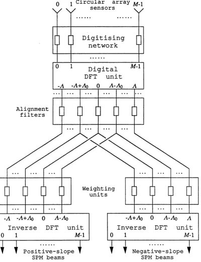
3.5 ► Fig. 3 5.1 Digital beamformer generating 2 sets of sectoral
phase modes 53
Fig. 3 5 2 Comparative phase plot and amplitude patterns for a
pair of sectoral phase modes 54
Fig. 3 5 .3 M ultibeam null-steering scheme incorporating
sectoral phase modes 56
Fig. 3 5 .4 A directional beam with a designed pattern null formed close to 30“ by the phased subtraction of
two SPM beams 57
3.6 ► Fig. 3.6.1 Digital implementation of phase mode coefficient
response 60
Fig. 3.6.2 Poles of l / 2^(z) 61
Fig. 3.6.3 IIR frequency-sampling phase mode filter 64
Fig. 3.6.4 n R phase mode filter: direct-form implementation 65 Fig. 3 .6 5 FIR phase mode filter: direct-form implementation 66
4.5 ► Fig. 4 5 .1 Single beam co-phased correction 76
Fig. 4 5 2 Single mode correction 78
Fig. 4 5 .3 Multimode correction using a pre-DFT matrix 79
4.6 ► Fig. 4.6.1 Two-stage multimode correction 80
1 0
4.8 ► Fig. 4.8.1 Simulated amplitude plots of digitally filtered phase modes no. 0,1 and 2 from a 7-element circular array
at frequencies: 12,18 and 24 kHz 87
Fig. 4.8.2 Simulated phase plots of digitally filtered phase modes no. 0,1 and 2 from a 7-element circular array
at frequencies: 12,18 and 24 kHz 88
Fig. 4.8.3 Simulated mode-space beam from digitally filtered phase modes -2 to 2 excited in a 7-element array at
frequencies: 12,18 and 24 kHz 89
Fig. 4.8.4 Simulated sectoral phase modes from digitally filtered phase modes {-2 to 1} and {-1 to 2 } excited in
a 7-element array at frequencies: 12,18 and 24 kHz 90 5.5 ► Fig. 5 5 .1 MUSIC spectral pattern for two uncoirelated sources 144
Fig. 5 5 .2 MUSIC spectral pattern for unsmoothed arrays
excited by two 99% correlated sources 145
Fig. 5 5 .3 M USIC spectral pattern for spatially-smoothed
arrays excited by two 99% correlated sources 146 Fig. 5 5 .4 MUSIC spectral pattern for a lO-sensor/5-mode
circular array excited by two fully correlated sources 147 Fig. 5 5 5 Application of spectral MUSIC for two uncorrelated
sources: rms error patterns 148
Fig. 5 5 .6 Application of spectral MUSIC for two uncorrelated
sources: angular bias patterns 149
F .l ► Fig. F.1.1 General flow chart 232
F.2 ► Fig. F.2.1 Welcome menu 233
Fig. F.2 2 Quit menu 233
F.3 ► Fig. F.3.1 Main menu screen 234
F.4 ► Fig. F.4.1 Save input menu screen 235
F.5 ► Fig. F.5.1 Load input/output menu screen 236
F .6 ► Fig. F.6.1 Input menu screen 238
F.7 ► Fig. F .7.1 Set menu screen 240
F .8 ► Fig. F.8.1 Random menu screen 241
F.9 ► Fig. F.9.1 Load element pattern file menu screen 242
F.IO ► Fig. F .l0.1 Options menu screen 245
F . l l ► Fig. F .l 1.1 Corrections menu screen 246
F.12 ► Fig. F.12.1 Output menu screen D screen 248
Fig. F.122 Output menu screen P screen 249
Fig. F.123 Output menu screen M screen 250
11
F.13 ► Fig. F.13.1 Direct weighting menu screen F.14 ► Fig. F.14.1 Modal weighting menu screen F.15 ► Fig. F.15.1 Display menu screen
F.16 ► Fig. F.16.1 Customise menu screen F.17 ► Fig. F.17.1 Save output screen
252 253 255 256 258
L m t © Î
Section
Page no.
3.2 ► Table 3.2.1 Uniformly excited mode-space beams from an
8-element array [omnidirectional radiators, 0.51 inter-element spacing]
Table 3.2.2 Uniformly excited mode-space beams from an
8-element array [omnidirectional radiators, 0.41 inter-element spacing]
3.5 ► Table 3.5.1 Angular errors in m ultimodal DF due to the presence of a second signal
F .l ► Table F. 1.1 Program structure
41
42
1 2
1. IN T R O D U C T IO N
1.1 GENERAL
The circular symmetry of ring and cylindrical arrays has attracted the attention of antenna and sonar researchers over the past sixty years. Potentially, these arrays offer 360° azimuth coverage for communications, direction-finding, radar and sonar applications, and may be installed on or conveniently wrapped round land, naval or airborne platforms. However, the rapid theoretical and technological growth in the related field of linear and planar arrays as well as the more complex and lossy feeding schemes devised for the earlier circular arrays, have inevitably limited the interest in their implementation and have held back their development. The past three decades have seen significant progress in the analysis of circular arrays, based on the concept o f phase mode excitation, which has led to the development of ‘multi-modal’ direction-finding systems and to new techniques for the synthesis and steering of directional beams and nulls.
Sonar transducer arrays of various shapes have likewise been under research and development for many years [Hay 20], [HoL 47], [And 63], [Que 70]. Experimental as well as operational arrays of (receiving) hydrophones and (transmitting) projectors in linear, planar, circular, cylindrical, and spherical arrangement have been built and used for passive or active source detection and localisation, for minesweeping, fish finding, communication and telemetry [Uri83], [Bur91]. The low (acoustic) speed of propagation in water has led to the development of multiple-beam sonar array systems with the emphasis being placed (in the case of passive sonar) on true time-delay beamformers which could handle the wide bandwidths involved. Aided by the low frequencies of the useful ‘sonar spectmm’, fully-digital beamformers have, to a large extent, replaced the earlier analogue networks of receiving sonar arrays, thus opening the way to more elaborate signal processing algorithms [And 60], [Cur 80].
Illllll 13 lllllllilllllii __________________________________________________________ Introduction
processing m ethods that use the information available in the received (and sampled) incom ing wavefront, subject to som e assum ptions, to (statistically) enhance the system perform ance in detecting and separating betw een closely-spaced sources. They are generally relevant in the context o f digitally processed receiving arrays o f arbitrary shape, but a number o f important high-resolution schemes have been either restricted to, or better m odelled, when applied to equi-spaced linear arrays. The inherent sym m etry and full peripheral coverage that characterise sensor arrays with circular geom etry have, rather surprisingly, attracted only lim ited interest o f authors in the field [Zey91], [Roc 88], [Mes90].
Papers on circular arrays started to appear in the 1930s dealing mainly with the azimuth and elevation patterns as well as the directivity of co-phased, equi-phased and periodically-phased arrays [Ste29], [Chi36], [Han38], [Han39]. The basic radiation properties of ring and cylindrical arrays, their radiation impedance and directivity continued to feature in later works [Car43], [Pag48a], [Pag48b], [LePSO], [KuN 51],
[KuN 53], [Ti l55], [KuN56], [Kin56], [Wa i58], [CHU59], [Mir59], [Hic60], [Hic61], [Hic 63], [Mac63], [Roy64], [Roy66], [Che67], [Kin68], some of which included an analysis o f concentric ring arrays proposed for improving pattern control [Ste29],
[Han38], [Han39], [Pag48b], [LeP50], [Ste65], [MAW 68], [Got70]. The synthesis of directional beams based on co-phased (or close to co-phased) excitation has likewise provided a popular subject of research [DuH 52], [Tay52], [Zm 64], [Fen65a], [Fen65b],
[Jam65], [Mot68], [Tse68], [Re d70], [Col70], [Got77], [Nag78], [Wat80], although the development o f the phase mode excitation concept [CoL 69], [Pro72], [DAv81a],
[Day 83] in the 1960s has led to a simple transformation from the then well- established linear array synthesis techniques to circular arrays [Day65b], [Lon67],
[Rah80], [Rah81], [Rah82], [Jon89], [Jon90]. Beam scanning and multi-beam forming which had previously required the commutation of excited array sectors, the switching o f a feed lens ports or a phase-modulating network (for continuous beam rotation) [NEF 50], [NEF 60], [Tan62], [McC 63], [Day65a], [Fen68], [Lon68], [Boy68],
1 .1 G e n e r a l ___________________________________________________________________________ iilllllililllli 1 4 |||||||
(how ever im plem ented) relates to obtaining a non-rotating directional radiation pattern from an antenna mounted on a spinning spacecraft [Gre 74]. N ull forming and null steering techniques have similarly benefited from the novel phase-mode approach making it possible to synthesise omnidirectional ‘m odes’ as w ell as directional beams with a specified number o f steerable pattern nulls [LiM 75], (Lim 77], [Day 77], [Riz77], [Day 78a], [Dav 78b], [Day 81b], [Gri 86], [Kar 86], [CvE 88a], [Cve 88b].
Early applications considered for circular arrays included direction finders [Cra47], [Ear 47], [RiN 56], [Bai60], [Get 66], [Wun66], [Get 78], [KuM 83a] o f which the W uUenwever array is perhaps the m ost w ell known, naval and air navigational aids [Han 53], [CHR 74], [She 74] and HF communications antennas [Sta 69]. The classic 4-elem ent A dcock array patented in 1919 and more so the 8-4-elem ent (interleaved) A dcock are in fact examples o f a circular array implementation o f a direction finding system [CR A 47], [Adc 19], [Guy 83a]. More recent circular-array D F techniques are based on multi-beam amplitude comparison, multi-modal phase comparison, a nulling schem e or any combination o f the above [Cve 88a], [Cve 88b], [Reh 80]. The formation o f nulls to suppress interference may also be achieved through the use o f adaptive hardware and software, applicable at either element level or at m ode level [Guv 81].
C losely related with the idea o f adaptive array processing are superresolution techniques for the spatial resolution o f incident plane w aves emanating from a number o f far-field sources [JoH 86], [Nic 87]. A variety o f algorithms have been developed and analysed in the literature, among them scalar-search (one-dimensional parameter-search) methods such as Capon’s M VDR, Burg’s Max-Entropy, MUSIC, and M in-N orm [Cap 69], [Bur 67], [Bur 68], [Bur 75], [Sen 79], [S œ 81], [Bm 80], [Red 79], [KUM83b], [KuM 83c], [Nic 88], [LiV 90] search-free (translational invariance) methods such as ESPRIT and TAM [Pau 85], [Pau 86], [Roy 86a], [Roy 86b], [Roy 87], [O n 88], [Roy 89], [OTT 90], [Orr 91], [ViB91a], [LiC 91], [KuN 86], [RAO 88], [RAO 89], [LiV 91] and vector-search (multidimensional) schemes such as IMP, Stochastic Max-Likelihood, Deterministic M ax-L ikelihood and W SF [Tup 82], [Mat 89], [KAV 91], [CLA 88], [CLA 91], [Sch68], [V an68], [Ban71], [Lig73], [Ows 81], [Wax 83], [Wax85], [Boh 84], [Boh 85], [Boh 86], [Jap 88], [Zis 87], [Zis 88], [San 87], [Sto 89], [STO 90a], [STo90b], [Sto 91], [OTT 89], [ O n 92], [Vm91a], [Vm 91b].
1 5 lllllllilllllii _________________________________________________________________Introduction
Study, has, however, excited but fleeting consideration in the literature [Moo 80], [Mu 81].
1.2 OBJECTIVES AND LAYOUT OF THESIS
Despite the dearth of published material in the field of circular arrays for sonar applications, most antenna array techniques for HF, VHP, UHF and microwave frequencies are basically applicable to sonar arrays. In fact adapting these techniques to sonar array systems means that traditional beamforming matrices whose imperfect analogue components have often limited their performance at microwave frequencies, may now be implemented digitally in hardware or in software, thereby allowing complex processing configurations and making the systems more amenable to corrective calibration and alignment schemes. Indeed, it may well be argued that the context of our study, which had initially been targeted at circular sonar arrays, has somewhat shifted to address circular digitally-processed receiving arrays o f either antenna elements or sonar hydrophones; in the latter case, though, one has the double benefit of both low frequency and manageable array size.
Our research study thus aims at exploring theoretical and practical aspects of conventional as well as high-resolution circular-array processing schemes for sonar applications, adapting some of the established circular-array techniques, as well as applying a number of new ideas to circular sonar arrays fed by digital beamformers. The material contained in this thesis is organised as follows:
CHAPTER 2 reviews some of the basic concepts involved in the analysis o f discrete circular arrays and considers some transient aspects of the array radiation patterns.
CHAPTER 3 deals with conventional beamforming and nulling techniques based on phase-mode analysis, introduces the idea of directional multimodal direction finding based on the new notion of sectoral phase modes, and studies the options and limitations of wideband mode alignment which directly affect the usefulness of the above techniques.
CHAPTER 4 exam ines the effect o f random aperture errors on the performance o f a m odally formed beam and introduces a correction schem e which is designed to com pensate for deterministic or random variations in elem ent radiation pattern behaviour and in array channel responses.
1 .2 O b je c tiv e s an d layou t o f t h e s is ________________________________________ iiillllllillill 1 6 Illllll
covariances, and to the possible implementation of spatial and ffequency-domain smoothing.
CHAPTER 6 concludes the main part o f the thesis with a summary o f the main results and recommendations for further study.
CHAPTER 7 holds the bibliographical references quoted in the thesis and is divided into five sections, each containing the references for the respective chapter and its appendices. Publications are quoted in the text using a bracketed ‘key’ comprising the first three letters of the (first) author’s surname and the last two digits of the year of publication. Whenever two or more publications share the same key, they are distinguished by appending a, b, etc. to their respective keys. Thus [Day78a] and [Day78b] refer to two different articles both of which had D. E. N. Davies as principal author, and both of which were published in 1978.
1 8
2. B A S IC C O N C E P T S
2.1 GENERAL
The idea of stacking discrete aperture elements of an antenna or sonar system in a regularly-shaped array fed by a power combining/dividing network saw its first (antenna) implementation in the late 1920s. Such an arrangement allows the synthesis of prescribed radiation beams through the control o f the aperture distribution, enhances the single-element signal-to-noise ratio (SNR) in reception^, enables the delivery o f high ERP^ in transmission through the use o f the active array^ concept and provides the basis for electronic scanning^ and m ultiple beamforming®. Although the radiation fields produced by an excited array (and likewise, the signals picked up by an array from outside sources) are governed by the solution to the wave equation® under the appropriate boundary conditions imposed by the array structure and loading, the underlying approach behind array theory is the principle of superposition. Accordingly, the radiation pattern of the array at a given observation angle‘s is obtained by a linear combination of the element-pattem fields
^ The single-element SNR is improved under the assumption of low aperture correlation of the received noise and low loss of the feeding network.
2 ERP stands for the Effective Radiated Power of the array, denoting the power per unit solid angle transmitted by the array in a given direction, divided by An.
^ An active array uses a set of power amplifiers whose outputs are combined in space. The amplifiers are attached to the array elements or distributed within the branches of the feeding network, replacing the traditional approach of a single power amplifier at the input.
^ Electronic scanning refers to the electronically-controlled inertialess movement of an array radiation beam via the controlled switching of element channel phases or delays.
® A multiple beamformer is an array feed network that can simultaneously generate a set of radiation beams, ordinarily at different directions.
® The wave equation is derived in a source-free region from either Maxwell’s equations for the electric and magnetic fields (e.g. [Har61], [Col91]) or from the hydrodynamic equations for the
acoustic pressure and particle velocity fields [Bre80].
Illllll 1 9 lllllllilllllii _____________________________________________________________B a s ic c o n c e p t s
in that direction. Note though that each element-pattem contribution refers to the radiation pattern o f a single array element in the presence o f all other elements, but such that the superimposed parameter (say, incident feedline mode) does not excite any other element. In the inevitable presence of inter-element coupling, superposition of incident-modes is therefore only applicable in a matched-terminated environment of the surrounding feedlines. The shape o f each element pattern is theoretically obtainable from the exact solution of the prevailing boundary-value problem, and in the case o f periodic (infinite) linear or planar arrays of closely-spaced radiators, it is also fully expressible in terms of inter-element coupling coefficients. Practically, though, the required patterns may be measured on the antenna or sonar range, and we shall therefore assume their availability in the pursuing analysis.
Superimposing the radiation patterns o f identical array elements, all facing in the same direction®, results in a separable spatial array pattern that is the product of the element pattern with the array factor. The latter pattern which is controllable via the (complex) weight excitation of the element signals at the array aperture, is the main contributor to the shape of the array radiation pattern, its beamwidth, sidelobe level and peak direction o f its maximum lobe (i.e. scan angle). The element pattern, being typically characterised by a relatively broader main radiation beam, affects these pattern parameters to a much lesser extent, and has its main influence on the potential angular coverage o f the array, and in the electromagnetic case, also on the polarisation of the radiated fields. Naturally, the array pattern is also affected by geometry. Under a large inter-element spacing, the effective spatial sampling involved in the formation o f the array factor may, in the case o f a regularly-shaped array, give rise to visible Floquet modes commonly referred to as grating lobes
[Ami 72], a phenomenon that is the spatial manifestation o f the time-domain under sampling occurrence of aliasing®. Grating lobes may be somewhat suppressed by the directional properties of the element pattern, and are diffused on departure fi*om regular linear or planar geometry.
The work contained in this thesis is devoted to circular arrays o f radially- symmetric elements, also known as ring arrays. Unlike linear or planar arrays the radiation pattern of a circular array is not separable and spatial-aliasing contributions
® Strictly speaking, for all element radiation patterns to be identical, all elements must 'sense' the same array environment This imposes a periodic structural constraint of an infinitely-long linear or planar array of uniformly spaced radiators.
2 .1 G e n e r a l ________________________________________________________________________ iillllillilllll 2 0 Illllll
are not represented by distinct grating lobes. In this chapter we review two fundamental feeding concepts on which much of the analyses and implementations of discrete circular arrays have been based, namely the beam-cophased and phase mode excitation schemes.
Beam-cophased (or ‘phase-compensated’) excitation involves the phase equalisation of the contributions from all the array element, when the array receives a signal from (or transmits to) a specified angular direction. In the case of a linear or planar phased array the elements are co-phased by the (controlled) application of a linear phase taper across the array, whose gradient determines the scan angle of the array radiation beam. Although the pattern’s characteristics such as directivity^®, beamwidth and sidelobes are separately controlled by the (usually constant) amplitude weighting taper (shading), the gain, beamwidth and sidelobe level typically deteriorate with scan, limiting the angular coverage of such arrays to (depending on bandwidth) 90°-120®. The beam-cophased excitation for circular arrays is a direct extension o f the linear array phasing concept and has consequently received considerable attention as a directional beam forming technique. Associated with this concept is the idea of co-delayed excitation whereby true time-delay equalisation of the element signals ensures the wideband operation of the array [Lon 68], [Sta69]. Unfortunately, in the case of a circular array, the required phase (or delay) taper is not linear (leading, in the case of analogue beamforming architecture, to more complex digitally-controlled phase or delay shifters); a reasonable sidelobe performance requires the application of both amplitude and phase taper to the co-phased (or co delayed) array, and scanning a beam (beyond a limited ‘within sector’ deflection) requires the commutation o f the excited array sector. The beamwidth o f the ‘wideband’ co-delayed circular array beam is frequency-dependent^^ just as in the case o f a linear array, but it does offer the advantage o f 360° coverage with virtually no attendant beam deformation.
The concept of circular-array phase modes refers to the excitation of the array elements with equal amplitude and a linear-periodic phase taper. The excitation of each ‘phase mode’ has been shown to form a far-field pattern which, on any conical surface around the array axis, approaches omni-directionality in amplitude with linear
10 The directivity of a radiation pattern is defined as the power per unit solid angle directed at a given direction (ordinarily that of the pattern peak), normalised to (l/4;r) of the total integrated power. Directivity is commonly expressed in dBi units (‘dB above isotropic’), denoting 10 times the logarithm to the base 10 of the above power ratio.
Illllll 21 lllllllilllllii ___________________________________________________ B a sin œ n rp n tfi
phase-versus-angle characteristics, whose average gradient depends on the number of excited phase cycles around the array. A phase moding network may be implemented as an analogue Butler matrix or as a digital Discrete Fourier Transform (DPT) unit, and as described in chapter 3, it provides (at least in theory) a convenient basis for multiple-beamforming, direction finding and null steering. The outputs of a phase moding network fed by a circular array share one common property with the outputs of a uniformly-weighted multibeam network connected to a (strictly speaking infinitely long) linear array. Each of the outputs represents an excitation condition under which the electrical (or acoustic) environment of all array elements is identical. This means that although they are all subjected to mutual coupling, their active radiation impedance^^ is the same and can in theory be compensated for by applying the appropriate filters to the network’s outputs.
In section 2.2 the far-field radiation pattern for a discrete circular array of co phased or co-delayed directional elements is formulated and represented as an infinite Fourier series with Bessel function coefficients. The transient effects associated with the reception of short or frequency-coded pulses by a co-delayed circular array are then considered in section 2.3. Finally, the far-field representation for each phase mode pattern as another infinite Fourier series with Bessel coefficients is developed in section 2.4. The result is classic although previous analyses have either treated non- directional elements or have simulated a discrete array by sampling a continuously excited array.
2 . 2 B e a m - c o p h a s e d e x c i t a t io n 22
2.2 BEAM-COPHASED EXCITATION
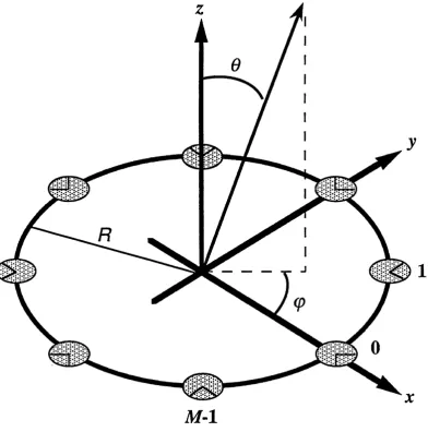
Consider an array of M elements (antenna radiators in an antenna array or acoustic transducers in a sonar array) uniformly arranged on a circle of radius R with radial symmetry, as depicted in Fig. 2.2.1 which also serves to define the relevant coordinate system. Let the radiation pattern of the m ’th array element as functions of direction and frequency be given by ^j{(oRic)sm e cos( . ( p - i T o n i M )co), where
c is the velocity of propagation and co is the temporal (angular) frequency. In the
above expression, the phase term el^o)Ric)smdcos(<p-27oniM) corresponds to the
propagation delay from a far-field source to the m ’th array element, with the reference point (of zero delay) chosen at the array centre; the remaining functional
M - l
Illllll 2 3 lllllllilllllii ____________________________________________________________ B a s ic c o n c e n t s
dependence o f the element pattern on direction and frequency is contained in
<p, oS) with serving as a convenient normalising constant. We generally allow gmi.0, (p, cû) to become complex, in which case the array elements either have no phase centres, or else these are not stationary with respect to direction and frequency^^. Assuming that over the relevant frequency band all element patterns are symmetrically identical and frequency-independent, we have:
gm <P^O)) = g (^, (p-27mlM) , m = 0 , l , - - - , M - l ••• (22.1)
and the far-field radiation pattern of the array is given by:
F ( 0 , ( p , û ) ) = ^ 2 47I& ^ _ 2 ;r /? z /M ) g ;( ^ % s m e c o s ( y - 2 ;D ? % /M ) . . . (2 2 2)
^m=Q
where { } is a complex weighting taper applied to the array channels. A directional pattern may be formed by constructively summing the contributions of some or all of the array elements in a given direction. In other words, at the specified frequency, channel phases are set (to within a constant delay) to:
{ain}= •■■{223)
where (Ô, ç>) define the desired beam pointing angle on the (0 , (p) coordinate system o f Fig. 2 2 .1 . Such phase setting is known as beam-cophased excitation. If all the array elements are co-phased and uniformly weighted in amplitude, the resulting radiation pattern may be given an alternative representation in terms o f Bessel
functions of the first kind. Let us first assume that g(0, (p) is a directional element pattern expressible as the following Fourier series:
g (e,< p )= 'Z hi(e)ej‘v ■■■(22.4)
The expression for the far-field array pattern is then given by.
A phase centre of an antenna or sonar element is the centre of a coordinate system with respect to which the (unwrapped) far-field phase pattern is either globally constant or has an extremum in a given direction. In the latter case one speaks of a non-stationary or apparent phase centre [Dys67].
2 . 2 B e a m - c o p h a s e d excitation ____________________________________________ lllllllilllllii 2 4
F ( 0 , (p, CO) =
M-l
= — ^ g { $ , Ç ' ^ ^ m ) d (o)R/c)[sm 6 cos{ç-27mlM)-sm 6 cos {<p-270n/M)]
^m=0 ^
M-l
= - L V hi ( 6 )e/ * ^ (2^/Af)t m g/ (ca^c)cos (t? - 27tmlM) • • •
m=0
where:
q>, 6, (p) - R[ (sin 9 cos (p-sia6 cos (p)'^ + (sin 0 sin <p - sin ë sin <p)^]
= R[sin^O + sin^ë - 2 sin0 sinëcos(ç>- (p)Ÿ^ • • ■ (22.6)
ü(ços 'â = R(sm 6 cos 9 - sin ë cos (p) • • - (22.7)
% in i)= R(smO s in ç - sin ë sin^) • • - (22.8)
But the term eJ (6>^c)cos (o - 27oniM) on the right hand side of (225) may be represented
by the following infinite Bessel series:
g7(©i^c)cos(t?-2;zm/M) = ^ yV y ( 0 3 ^ c ) g V -2wM/M) •••(22.9)
y=i-oo
where Jy{x) denotes a Bessel function of the first kind of order v and argument x. Substituting in (225) and changing the order of summations we then have:
I ~ M-l
F ( 0 ,( p ,û ) ) = ^ X hi(e)eJi<P X r M O X K l c ) e - J ^ - ^ [ ^ g-;(2;?/M)(i-v)m]
M ^
i=-I v!=-oo m=0
(2.2.10)
w ith I denoting the order o f the highest non-vanishing elem ent-pattern Fourier coefficient. Noting that the bracketed term in (22.10) is equal to:
M-l
^ = 8(i-v+ q M ) ■■■{22.11}
2 5 lllllllllllllii ____________________________________________________________ B a s ic c o n c e p t s
where 5 (n) is the Kronecker delta function,
^1 fi—0
S(n) = l >
0 n* 0
the expression for F (6, (p, cd) takes the form:
I F(0,(p,co) = ' £
i=-I q = - o o
OO J
q=-oo i—~I
= ' ^ Kg(œ,0, >» . . . (22.13)
q=-oo
where:
/
K^iO), e, 9) = E (0)Ji-HiM (.<mc)eJ‘(4 -^ . . . (22.14) i=-I
and use has also been made of the identity:
j-^ J .v ( a )= r J y ( a )
For the special case of element patterns that are omnidirectional in ç), the expression for the far-field pattern simplifies to:
F (0 , <p, CO) = A o (0 X f^ ^ J q u ic o iU c y e -j^ M o
q=-oo
= /zo(0 )UoioXRlc) 4- 2 ^ j^^JqM (co^c)cosiqMt>)] . . . (22.16)
<7=1
which, save for the /zo ( 0 element pattern variation in elevation, comprises simply the
2 . 2 B e a m - c o p h a s e d e x c i t a t io n iilllllllllllll 2 6 IIIIIH
Assuming that the desired beam peak is set to lie on the azimuth (0=;r/2) plane^^, the array azimuth pattern is approximately given by:
=[(cosç)-cos^)^ + (sin<p-sin^)^]^^
U—U—7Ü/^ f
= 2sm[((p-(p)/2]
F((p, œ) « J o [ 2 iœ R /c )sm ^ ^ ]
whereas in the main elevation plane,
iRlR = [ (sin 6 cos (p- cos (pŸ + (sin 0 -sin (p- sin (pŸ ] e=n!2 , (p=(p =» 1 • Û
= l- s m 6
and the elevation pattern is thus approximated by the expression:
F (0 , CO) « hoiO) Jo[(coR/c)(l - sin0)]
Note that strictly speaking expression (223) defines a ‘co-delayed’ rather than a ‘co-phased’ excitation taper, by which we mean that the array remains properly compensated regardless of the operating frequency. In the case of narrowband co
phased excitation at frequency cdq» i^and t) must be redefined as follows:
R[swP- 6 + {cûo/coŸ’sm ^S - 2 ^ s i n 0 sin è cos((p - (p)Ÿ^ • • ■(22.17)
% o s û - R(sin 6 cos (p - ^ s i n 9 cos (p) • • • (22.18)
!^sin Û = R(sin 9 sin q>- ^ s i n & sin (j?) • • • (2.2.19)
and the two special cases considered above are respectively modified to:
Fi(p, Û» = Jo [(.c o o m ii-^ -lf+ 4 (0 /(O o ) s i n 2 ( ^ ) ] i / 2 )
CÛQ Z
and
F (9, co) » ho(9)Jo {((OqRIc) I(cü/tao)sin0 - 1 1}
2 7 B a s ic c o n c e p t s
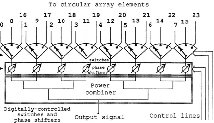
In practice not all the elements of a circular array are excited for the formation of a co-phased or co-delayed beam in a given direction. Since element patterns in an array environment are in general outward-directional, it is often wiser to generate the required beam using a typical aperture sector of 90“ to 120“ facing the specified beam pointing direction so that backward radiation in the form of sidelobes is reduced. A further reduction in sidelobe level may be achieved by the symmetric application of amplitude weighting, phase weighting or both^^, although mode-space beamforming described in chapter 3, presents a more systematic approach to pattern synthesis. A major drawback in the beam cophased architecture lies in the interlaced sector feeding and switching needed for multiple beamforming^^ and beam scanning respectively. The latter arrangement is exemplified by Fig. 2 2.2 which schematically describes a
120“ switched feeding configuration for a 24-element circular phased array.
To circular array elements
1 6 17 18 19 2 0 21 22 2 3
13 14
10 11
12
15switches
y phase shifter
Power combiner
D i g i t a l l y - c o n t r o l l e d s w i t c h e s a n d
p h a s e shift e r s Output signal Control lines
Fig. 2 .2 2 Feeding matrix for a 24-element circular phased array
15
16
A number of papers dealing with co-phased pattern synthesis and sidelobe reduction have appeared in the 1960s and ’70s - see for example [Fen65].
2 . 3 T r a n s i e n t e f f e c t s 28
2.3 TRANSIENT EFFECTS
When the bandwidth of the received signals is of the same order of, or greater than the reciprocal of the propagation delay across the array (as may be the case in the reception of frequency-coded or short CW pulses), the radiation performance of the array cannot be satisfactorily represented by its steady-state array pattern at a single frequency. The true time-varying response of the array depends on the characteristics of the received pulse as well as on the frequency dependence of the array radiation pattern.
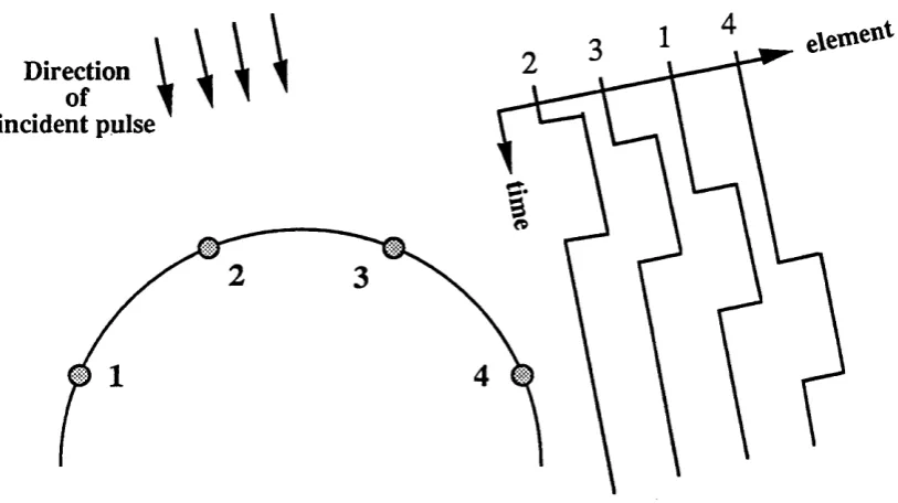
Qualitatively, the transient effects associated with the reception of a short CW pulse are fairly simple to visualise. Pulsed signals incident at the different elements of the array are in general temporally displaced depending on the array geometry and on the relative direction o f the radiation source. Unless these delays are negligible compared with the duration of the pulses, they may not all overlap in time — this is depicted in Fig. 23.1 for the case of a 4-element semi-circular array. Without appropriate compensation, the radiation pattern of the array will consequently be distorted by the fact that contributions from the array elements do not occur simultaneously, or equivalently by the frequency-dependent phase differences between the summed signals which make up the array response over the whole bandwidth of the pulse.
Direction incident pulse
etvf
2 9 iilllllllllllll ____________________________________________________________ B a s ic c o n c e p t s
A common method for the wideband compensation of either a linear array or a circular beam-cophased array is by the implementation of true time delays at the array channels. In the case of an M-element circular array of radius R the required delays (to within a constant delay) are:
'Vfn = (^ /c )sm 6 c o s((p -^ m ) 0<m <M -l
where (6, (p) define the direction for which the array is to be delay-matched and c is the velocity of propagation. These delays may be realised by using physical transmission line sections or, when digital beamforming architecture is employed, by utilising previously stored data samples in conjunction with interpolation filters for the reduction of delay quantisation errors. If the array is delay-matched to the direction of arrival of the signal, then at the beam peak direction all contributions are coherent and occur simultaneously. However, if a signal pulse hits the array from any other direction, especially well away from the main beam, channel contributions wül once more depart from proper tem poral alignm ent and will no longer be simultaneously processed. Depending on the shape and duration of the received pulse this delay mis-match may degrade the sidelobe performance of the array.
For a more quantitative examination o f a circular array response to a short CW pulse, let us consider the following signal travelling towards the array o f Fig. 2.2.1
from direction {6, <p):
where IJ(t) denotes the waveform envelope (a rectangular pulse, a shaped pulse etc.) and CÜO is the carrier (angular) frequency. At the m 'th array element the received
signal is given in the frequency domain by gm(0, (p, c y ) | ^ d f p ( r ' w h e r e
gm(0, <p, co) is the radiation pattern of that element, tc denotes the time of pulse arrival at the array centre and is given by:
(Rfc)sin0cos{(p-27Dn/M) • •. (233)
The summed response of the whole array is given by:
2 . 3 T r a n s i e n t e f f e c t s _____________________________________________________________ iilllllllllllll 3 0 IIIIIH
where n(co) is the Fourier transform of the waveform i7(r) and for a given set {Om] of
applied shading coefficients, F(fi, (p, co) is the steady-state array pattern given by
A f-l
F { e ,
=
(p,. •.
(235)^m=Q
The time-domain array response is therefore given by,
= da>ei<^0-‘‘)F(,e,<p,(iH-oi>o)ÎH.co) ■■■{23j6)
« / - O O
From (23.6) it is clear that if to within some delay response F{Q, <p, cû^ cûq) can
be made approximately fi*equency invariant over the bandwidth of i7(û)),
F (0 , (p, CÛ+ O)o) = e~j (p) • • • (23.7)
then:
F(0, (p,t) « F (0, q>)p(t-tc-td)ej^^^ • • • (23.8)
and the steady-state array radiation pattern applies. An inspection of (23.5) reveals (as expected) that this indeed is what beam co-delayed excitation sets out to achieve. By requiring that in the direction of the main beam:
= 0 » 0 <m <M -l
F(&, (p, ctH- Cüo) is made dependent only on the frequency response of the element patterns, which is assumed to be fairly flat over the relevant band. Away from the
main beam direction F(^6,<p,o>\-(ûo) is frequency dependent and should be
characterised by low sidelobes over the whole bandwidth of îli^cS) for the sidelobe
level of F (0 , (p,t) to remain low. Omnidirectional delay matching is possible, but as we show in chapter 3, it requires each array beam to be synthesised from wideband aligned phase modes. Phase modes are reviewed and discussed in section 2.4 of this chapter; their broadband alignment is treated in section 3.5 of chapter 3.
31 B a giç çp n ç e p ts
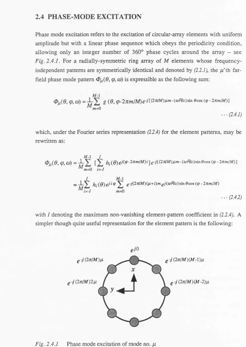
2.4 PHASE-MODE EXCITATION
Phase mode excitation refers to the excitation of circular-array elements with uniform amplitude but with a linear phase sequence which obeys the periodicity condition, allowing only an integer number of 360° phase cycles around the array - see Fig. 2.4.1. For a radially-symmetric ring array of M elements whose frequency- independent patterns are symmetrically identical and denoted by (2.2.1), the ^ ’th far-
field phase mode pattern (p, (û) is expressible as the following sum:
M-l
(p, CO) = S ( p -2 7tm lM ) e - j [ i' ^ ^ i ^ ) ^ ^ ' n - i c û R / c ) s m ecos { ( p - l n m l M ) ]
m=0
which, under the Fourier series representation (22.4) for the element patterns, may be rewritten as:
M - l I
(p, co) = — }i.(^Q^^j((p-27Cm/M)i-^g-j[i27C/M)fim-icûR/c)smecos (<jp - 2 n m /M )] ^ m = 0 i=-I
I M - l
_ _ 1_X h (^Q)eji 9 X £ - j ( 2 n f M ) ( j i + i ) m gj((ûRlc)s'm 6 cos ( ç - 27cmlM)
^ i = - I ‘
(2.42)
with I denoting the maximum non-vanishing element-pattem coefficient in (2.2.4). A simpler though quite useful representation for the element pattern is the following:
J
^-j(27tlM)(M-l)ii
g-j{2nlM)(M-2)gL
2 . 4 P h a s e - m o d e excitation ________________________________________________ iilllllllllllll 3 2
= . p > 0 ■■■(2.43)
with ho (6) denoting an arbitrary elevation dependence, for which the corresponding array pattern is
-co) = —^ ^ Q-j{27zlM)^m^[{(ùRlc)+j\np\sin ©cos {(p-lnmlM) . . . (2.4.4)
^ m=0
The term sin 6cos(9)-2wn/M) which appears in (2.4.2) is expressible as the
following infinite Bessel series:
^jicùRc) sinflcos {<p-2nmlM) = ^ jVJ^ Q'^^-jv{<p-2nmlM) . . . (2.45)
\^-eo
Substituting in (2.42) and changing the order of summations we have:
(p, co) =
/ ~ M-l
2 X y''-^v(^sin0)e/O -'')9’[ ^ ] £ g-;(2;r/M)(;x+i-v)m] ...(2.4.6)
i—~î y=-oo t?i—0
The bracketed term in (2.4.6) is equal to zero or to 1 according to the values of m, i
and V.
M-l
e-K2n/M)(fi+i-v)m^'^ S (^+ i-v+ qM ) (2.4.7)
^m=0
The expression for 0 ^ (0 , cp, co) therefore takes the form:
0^(e,(p,w ) = ' Z A,(e) 2 f q=-oo
/ _
=
E [Ê
(^ sin e)]d v O :M M )fq=-oo t=-/
■■■(2.43)
3 3 Iilllllllllllll ____________________________________________________________ B a s ic c o n c e p t s
where 6) is the frequency-dependent phase mode coefficient of order q for the
ji'th phase mode, and is given by:
/
e) = s (0) V,>^M [(û)R'c)sin0] ■.. (2.4.9) i=-I
The far-field pattern of a phase mode is thus expressible as a sum of the form
<p, <a) = X 6)e-i<M+‘!tf)<i> . . . (2.4.10)
q=-oo
which may be viewed as the azimuthally-omnidirectional linear-phase pattern
CpiQ{cû,0)e-iy-^^ distorted by an infinite series of higher order terms^'^. Note that (2A.10) still applies when element patterns of the form (2A3) are assumed, only each phase mode coefficient is given by (see appendix B.2 for details):
C^î(û). m = p A o (e );(^ -^ » * « V ,M [(^ + ;ln p )sin 0 ] ■ • • (2.4.11)
For array elements that are omnidirectional in azimuth, we have /z/ = 0 , zVO in {22 A), or equivalently p = 1 in {2A3}, both of which lead to:
CMi<o, e) v , M ( ^ s i n e ) ■ • • (2.4.12)
Since (2A.12) also applies to the dominant ^ = 0 mode, whenever the frequency and
the array radius are such th a t/^ (-^ ^ ) hits one of its zeros, there will effectively be a ‘hole’ in the far-field circumferential coverage of that mode around elevation zero
(0 = n fl). In the vicinity of the zero, the far-field azimuth pattern is not completely
cut out, but ripple from higher order terms (especially those characterised by <7 = ± 1) will dominate, and thus limit the practical usefulness of that mode. If on the other hand the element patterns are of the form:
2 .4 P h a s e - m o d e ex cita tio n ________________________________________________ iilllllllllllll 3 4
g(G, ç) = ^ e (0)cos2^ = ^g(0) [ l+ lc o s ç ) ]
then.
where Jy (• ) signifies the derivative of the Bessel function of the first kind with
respect to its argument. Since the zeros of /v(* ) and of Jy (• ) do not coincide for any
V, it follows that for this type of element pattern the phase mode coefficients never fall to zero. In fact noting that the zeros of a Bessel function of integer order are always real it follows that any element pattern of the form (2.4,3) which is either outward-directional (p < 1) or even inward-directional (p > 1) leads to phase mode coefficients (2.4.11) that never fall to zero.
One last result relates to symmetric element patterns given either by (2.4.3) or by (22.4) with:
hi(e) = h.i(e) , i > o
The phase mode coefficients of symmetric modes are then related by:
/
= E . . . (2.4.13)
* = - /
as can also be directly deduced from (2.4.11), where use has been made of the Bessel
identity (22 J5). Consequently if 0^(0, ç,co) is given by (2.4.10) then the
corresponding expression for (p, co) is:
0 .^(6 , «).£»)= X . . . (2.4.14)
q=-eo
IIIIIH 3 5 Iilllllllllllll _____________________________________________________________B a sin c o n c e p t s
jj, = -M/2 (when M is even) are the same, and both mode terms are ‘available’ in
^±M/2 (^» Û))» constituting a far-field pattern that is very different in both amplitude and phase from the desired linear-phase omnidirectional pattern^®:
^±M P. (^» Çy « C(m/2) o(G), 6 ) [e/W^) ç+ e-j^M i2) y] = 2 C(m/2)o(û>» cos(M(p/2)
2.5 CONCLUDING REMARKS
In this chapter we have reviewed the beam-cophased and phase-mode excitation methods for circular arrays. The first approach, although a direct extension of linear- array beamforming, does not lend itself to systematic pattern synthesis techniques and is quite awkward to incorporate in a scanning array system. We have seen that even when delay-matched, transient effects may alter the designed sidelobe performance of the array. A beam-cophased array of reciprocal transducers is also susceptible to aperture excitation errors due to the combined effect o f inter-element coupling and feed network back coupling.
The alternative approach o f transforming from ‘element space’ onto ‘phase-mode space’ provides us with a set of (possibly rippled) omnidirectional patterns, each characterised by a linear far-field phase. Although we have hitherto considered the synthesis of a single phase-mode pattern from an M-element circular array, it is simple in principle to simultaneously generate up to M independent phase modes with the aid of an analogue Butler-type matrix, or through a spatial Discrete Fourier Transform (DPT) operation on the digitised outputs of the array sensors. Phase modes are affected by mutual coupling, but since they each place all the array elements under identical periodic boundary conditions, the outcome is that each phase mode simply ‘acquires’ a new complex coefficient which is correctable through re calibration. Properly aligned phase modes may be weighted and linearly combined according to well established linear-array synthesis techniques, to form directional beams. This well known technique together with other existing schemes and some new related ideas, such as directional phase mode beams and omnidirectional delay matching, are discussed next in chapter 3.
The summed pair of oppositely-numbered phase modes is sometimes called an amplitude mode.
3 6
3. C O N V E N T IO N A L M O D E -S P A C E
T E C H N IQ U E S A N D
A P P L IC A T IO N S
3.1 GENERAL
Circular array phase modes provide a convenient basis for a number of interesting antenna and sonar array applications. Their most common use is in multimodal direction finding where the phases of several pairs of excited modes are detected and com pared, achieving the angular accuracy o f larger am plitude-com parison (multibeam) DF systems^. Other conventional techniques^ include the phased addition of adjacent modes to form patterns with phase-controlled steerable nulls, as a way of suppressing co-channel interference, and directional beamforming where phase modes are weighted, phased and combined by essentially linear-array feeders. Sections 3.2, 3.3 and 3.4 of this chapter are devoted to a short review of these schemes. The usefulness of the latter two depends on the broadband alignment of the phase modes, which calls for the separate deconvolution o f their dom inant coefficients. It is worth noting that once such wideband alignment is successfully implemented, the array becomes circumferentially delay-matched for incident pulses of lower bandwidth.
In mode-space beamforming a set of excited phase modes is treated, after some angular transformation, as omnidirectional elements of a fictitious linear array, where all phase modes are assumed to be aligned and distortions due to higher order modes are neglected. The modes are linearly combined using linear-array synthesis
^ In the traditional circular-anay amplitude-comparison DF system the array is fed by a multiple beam-cophased network (normally an RKR electromagnetic lens in the case of microwave antennas), in conjunction with a beam width-stabilising sidelobe-reducing interlaced conversion matrix. The attained angular resolution of the system is a function of beam width which in turn depends on the array dimensions. In contrast, the angular resolution obtainable fiom a multimodal array may actually improve (due to reduced ripple) when the array radius is decreased (up to a limit below which radiation efficiency drastically drops)
Illilll 3 7 Iilllllllllllll ___________________ C o n v e n tio n a l m o d e - s p a c e t e c h n iq u e s an d a p p lic a tio n s
techniques (for, say, sidelobe suppression), and under broadband mode alignment, the generated beams remain unchanged with frequency. The essence of this well known concept and a convenient technique for exciting a multiple set o f directional beams are briefly recalled, together with a number of examples, in section 3.2,
Multimodal direction finders detect and compare the phases o f pairs of phase modes, utilising the approximate linear-phase characteristics of their far-field patterns to provide an output voltage that is linearly proportional to the angular location of a single far-field source. It is commonly accepted that to within an angular ambiguity of 180°, no mode alignment or look-up calibration tables are theoretically required. In section 3.3 we show that under some reasonable and easily verifiable assumptions, the above angular ambiguity may in fact be eliminated.
M ode-space null-steering is based, as described in section 3.4, on a tree arrangement that starts by the phased subtraction o f adjacent phase modes and continues, if desired, by a similar subtraction of adjacent output beams^. Provided the subtracted modes are properly aligned, this scheme yields far-field patterns with one independently-steered null per stage. The incorporation of a null-forming network in a DF system may provide an iterative (though non-adaptive) direction finder that can handle a multiple source environment [CVE 88a], [CvE 88b].
In section 3.5 we introduce a new type of beams which we name sectoral phase modes. A sectoral phase mode is a directional beam with phase-mode-like phase behaviour, which may be synthesised by a linear combination of omnidirectional phase modes that have been equalised over the relevant frequency band. Sectoral phase modes allow the phase-mode concept to be confined to a single or multiple angular sectors instead of the usual omnidirectional phase-mode coverage. A single sector implementation may be used to limit the spatial sensitivity of a circular array to a given (possibly large) angular zone, whereas multiple-sector applications include phase-comparison direction-finding with enhanced immunity to interference and sectorally-controlled multibeam null-steering.
The question o f bandwidth is finally dealt with in section 3.6, which includes a somewhat academic search for the ‘optimal’ element pattern, but also a discussion on the viability and design considerations for a set o f stable phase mode filters. The chapter concludes with a summary of the main techniques, their advantages and
possible limitations.
3 . 2 D ir e c t io n a l m u l t i b e a m e x c i t a t io n ____________________________________________ iilllllllllllll 3 8 IIIIIH
3.2 DIRECTIONAL MULTIBEAM EXCITATION
Approximating a set of phase mode patterns {0 ^ ( 6 y (p, by:
0fi(OyÇyû))--C^o(û)ye)e-jt^<P , -A< fi< A - '( 3 2 J )
where the coefficients {C^o]^ are all non-zero, enables one to use linear array
techniques to synthesise a low-sidelobe (2A+l)-“element” directional beam in any direction [Day65]. The application of a linear array aperture taper to form the weighted sum of distortionless phase modes, each normalised to its zero-order coefficient results in a radiation pattern that is identical to the array factor of the corresponding linear array but with the following coordinate transformation:^
2;r(dA )sinç)[lineararray] ( p [circulararray] •••(322)
where d is the inter-element spacing for the linear array. This means that as long as (32.1) holds, the resulting array pattern is independent of frequency, provided a way is found to flatten out the frequency responses of all the zero-order mode coefficients.
As previously noted, a multiple set of (2A +1) phase modes may be generated from an
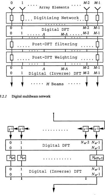
M-element circular array with the aid of an M x(2A +1) analogue Butler matrix, or its digital equivalent of a spatial DFT unit. Cascading the modeforming unit with an array of deconvolving filters, a set of weights and an inverse DFT unit (assuming digital implementation), as schematically illustrated in Fig. 3.2.1, results in the simultaneous excitation of M (possibly broadband) radiation patterns^
A
E m ( ç ) ) * - V E a^e-J^^(v-27cm/M) ^ 0< m < M -l •••(323)
with respective beam pointing d irections {(pm = 27rm/M). One possible implementation for each of the digital filters in Fig. 32.2 is illustrated in Fig. 3.2.2, where two temporal DFT units are used to divide the frequency band into N (q
separately aligned bins with complex weights { } which are given by:
^ We refer here to the radiation pattern on the xy-plane from a circular array lying on the same plane and from a linear array lying parallel to the y-axis.
^ Each weighting unit may in fact be incorporated with the corresponding mode filter.
39 ■C onventional m o d e - s p a c e t e c h n iq u e s a n d a p p lica tio n s
0 1
; NMMWM
M-2 M -l
A r r a y E l e m e n t s
D i g i t i s i n g N e t w o r k
0 ^ D i g i t a l DFT M-2 M -l
0 1 ...A M-A . . M-2 M -l
P o s t - D F T f i l t e r i n g
i
P o s t - D F T W e i g h t i n gI
I. . . r
0 1 A M-A
0 1 D i g i t a l (Inverse) DFT M-2 M-l
n
M Beamsn
Fig. 3.2.1 Digital multibeam network
D i g i t a l DFT
D i g i t a l (Inverse) DFT
3 .2 D irection al m u ltib eam excitation 4 0
- l/C^o(û)= nCûsINoy, 6 = %!X) , 0<n<Ny^-l
where is the (angular) sampling frequency. However the Fourier transform of
yC^o (o)y 6 = n il) is not necessarily finite in its extent, and consequently the required order N o for this finite impulse response (FIR) approach (as well as other FIR filter realisations) may become excessively large (see for exam ple [OPP 76])."7 Alternatively, the order of an HR (infinite impulse response) filter realisation is
shown in section 3.6 to depend on the Fourier transform of C^o(ù), 6 = n il) whose extent is indeed finite.
Let us now return to expression (323) for the approximate far-field pattern of mode-space radiation beams. Such a multiple set of beams with a reduced sidelobe level is displayed in Fig. 3.2.2 for the case of an array of 7 directional elements at 0.456-wavelengths spacing®, using a set of 5 aligned phase modes (u = -2 to 2), pre-weighted as follows:
Mode - 2 - 1 0 1 2
W e ig h t s - 1 0 . 5 dB - 2 . 3 dB 0 dB - 2 . 3 dB - 1 0 . 5 dB
- 1 2 0 - 6 0 0 6 0
Angle (d eg rees)
Fig. 3 .2 3 Multibeam pattern formed by 5 weighted modes from a 7-element array
(H = 0.508A, g(p{(p) = 0.612+0.384 cos 9+0.004 cos2(p)
^ This really depends on the smoothness of each of the phase mode coefficients, which in turn is a function of the element pattern.

![Fig. 3.6.4), with the set of weights [u'^iohd] substituted for the values {2^»}](https://thumb-us.123doks.com/thumbv2/123dok_us/9159368.1453961/87.595.50.472.299.587/fig-set-weights-u-iohd-substituted-values.webp)
