824 |
P a g e
AUTOMATIC WHEELCHAIR USING EYEBALL
SENSOR
Rajavenkatesan.T
1, Nagalakshmi.S
2, Ram Prasath.K.P
3,
Venkataramanan.S
41
Assistant Professor.Dept., of EIE, K.S.Rangasamy College of Technology, Tiruchengode, (India).
2,3,4
UG Students, Dept., of EIE, K.S.Rangasamy College of Technology, Tiruchengode, (India)
ABSTRACT
An automatic wheel chair is a mobility-aided device for persons affected by moderate, severe physical
disabilities, and chronic diseases as well as elderly. Many people with disabilities do not have the ability to
control the powered wheel chair using joystick and hand movements as it is tougher for the person to move and
it is software oriented. The proposed method consists of hardware which eliminates the individual’s work using
eyeball sensor. The proposed model uses an eye ball movement tracking system to control electronic wheel
chair. Once the movement has been processed and it is given to the microcontroller. The microcontroller
process depends upon the feed coding and the output is gives in to the driver circuit. Also, the obstacle detection
sensors will be connected to give necessary feedback for proper operation of the wheelchair system. All four
wheel will be connected to driving circuit that will move to wheelchair based on eye ball movement.
Keywords: DC motor, Eyeball sensor, IR sensor, Micro controller.
I. INTRODUCTION
There are patients who have lost control of both arms and legs, as a result of higher level spinal cord injury or
brain and nervous system disorder. These kinds of patients can't use the standard wheelchair which depends on
the arms muscular force to move the wheelchair. At the same time, they can't use the electrically powered
wheelchair which is controlled by joystick. So these types of patients still want the help of another person to
move their wheelchair from one place to another. Many researchers have proposed different methods to control
the wheelchair. One of the possible solutions for them is to use their eye ball movement to control the
wheelchair. The control of the wheelchair is depends upon the eye ball sensor, which will do the functions like
right, left, forward and reverse operations.
The wheel chair is designed in such a way that it can move freely without external support or dependency.
Through this feature the patients can enable movements of their wheelchair as per their desire.
II. LITERATURE SURVEY
There were many pervious works carried out on electronic Wheelchairs. These are a few of them which helped
us to get ideas for our current prototype.
825 |
P a g e
correctly when recognized. An IR obstacle detection unit can be used which is fixed to the wheelchair to avoidpossible accident A resistive touch screen will be best suited for this application as it is low cost and has greater
lifespan compared to other types of touch screens available. From the screen, user can either select a predefined
path or can create their path in real-time
.
The drawback of this method is that, it is less accurate in the turning ofwheelchair
In [2] voice and Gesture Based Electric-Automatized Wheelchair Using ARM”, this method is very greatly user
free and comfortable for elders with limbs impairments. The benefit of this method is to people who are unable
to perform simple movements with their hands. This technique is used language and hence can be considered
universal. A voice recognition IC is interfaced with a microcontroller. This IC accepts the input from the user as
voice commands which are then converted to digital signals that a microcontroller can process. It will produce
the desired output which controls the wheelchair
In [3] “automatic Wheelchair Controlled using Hand gesture”, an EMG Sensor, and guide Signal Separation‟
can be used in this method. A system is designed which uses an IR sensitive camera to identify the gesture
shown by the user. The capture images of the gesture are given to the microprocessor which does further
processing. The drawback of this method is that it cannot be used by the persons who are suffering from nerve
disorder and stoke etc.
III. HARDWARE IMPLEMENTATION
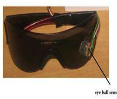
3.1 Eyeball sensor
The basic principle of this direction sensing is the color of the eyes. There are two main color sin the human
eyes. i.e., black and white. The infrared light rays passed to the eye and measure the white portions.
The Infrared sensors are placed on either side of the sensor. The eye ball sensor is connected to the
microcontroller. It will perform the analysis, processing and amplification of the signals from the sensor‟s
eye-ball movements. The eye eye-ball movement is an analog signal which can be converting into a digital signal.
Depending upon the movement of the eye ball and controller provides the output. It can be passed through
driver circuit to their direction of right, left, forward, reverse directions.
The sensor output is based on the eye ball. If the eye ball is large then the accuracy is more. If the eye ball is
small then the accuracy is low.
826 |
P a g e
3.2 Motors
The Geared type dc motor with 12Vpower supply and 45rpm motor is used to move the wheelchair. DC motors
are available from15W through 6,0kW. These motors are high torque, continuous S1 or S3 periodic-duty
products suitable for a wide variety of applications ranging from pumps to propulsion. The motors operate on
battery power or generated “pure” DC power. The motor will take input from the driver circuit, depending upon
input the motor move in the directions of right, left, forward, reverse.
Table1: Truth Table Representing the Working of the Motor
The two motor is connected to the driver circuit and it will move the wheelchair based on the input signal from
the circuit, the truth table becomes as shown in table2
Table2: Truth Table for Controlling Two Wheels Simultaneously
3.3 Motor Driver
L293D is a dual H-Bridge motor driver with one IC interface two DC motors which can be controlled in both
clockwise and anti-clockwise direction. L293D has output current of 600mA and it can be amplifies the input
signal form controller. This device is suitable for use in switching application at frequencies up to 5 kHz. The
output supply (VCC2) has a wide range from 4.5V to 12V, which is suitable for low speed operation.
3.4 Microcontroller
The ATmega8 contains 8K bytes On-chip In-System Reprogrammable Flash memory for program storage. It is
827 |
P a g e
It has 3 ports such as port B, port C, and port D. The port B is connected to the eye ball sensor. As inputs, Port Bpins that are outwardly pulled low will source current if the pull-up resistors are started. The Port B pins are
tri-stated when a reset condition is on, even if the clock is not running. Depending on the clock pulse, PB6 can be
used as input to the inverting amplifier and input to the internal clock operating circuit. Depending on the clock
selection pulse, PB7 can be used as output from the inverting amplifier
.
The port C is connected to the drivercircuit for motor input.Port C is a 7-bit bi-directional I/O port with internal tell off resistors (selected for each
bit).
Block Diagram
Figure 3. Block diagram of the project
The Port C output buffers have balanced drive characteristics with both high sink and source capability. As
inputs, Port C pins that are externally pulled low will source current if the pull-up resistors are started. The Port
C pins are tri-stated when a reset condition is on, even if the clock is not running. The port D is connected to the
driver circuit for motor output. The Port D output buffers have symmetrical drive characteristics with both high
sink and source capability. As inputs, Port D pins that are externally pulled low will source current if the pull-up
resistors are activated. The Port D pins are tri-stated when a reset condition becomes active, even if the clock is
not running
.
The controller is processed depending upon the coding.3.5 Obstacle Sensor
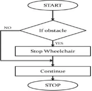
The obstacle sensor is placed at the front of the wheelchair. It is used to provide information on the objects in
the direction of the wheelchair. It is consists of transmitting and receiving section. The IR signal is passed
through in the direction and it can be received. If any obstacle in the direction of wheelchair, it will sends 5V
supply to controller, then wheelchair is stopped. Otherwise 0V supply is given to the controller. Battery
Power supply
Eyeball sensor
MICROCONTROLLER
(ATMEGA 8)
Motors
L293D Driver LCD
828 |
P a g e
Figure 4. Flow chart of obstacle sensor
IV. KEIL C COMPILER AND FLASH MAGIC BURNER
We are using the Keil C Complier software to program the microcontroller in Embedded C codes.[7] The Keil
C51 C Compiler for the ATmega8microcontroller. It provides more features than any other 801151 C compiler
available nowadays. The C51 Compiler allows you to write 8051 microcontroller application sin C that, once
compiled, have the efficiency and speed of gathering language. Language extensions in the C51 Compiler give
you full access to all capital of the 8051.Flash Magic Burner is an application for programming
microcontrollers. The program will routinely verify the chip after the Hex file is loaded to it.
WORKING
The eye ball sensor sensing the position of the eye and given to the microcontroller. It will convert input to
digital signal and send to the driver circuit. The output of the controller is digital signal. It has L293D IC which
converts digital to 12V analog signal. The obstacle sensor is also connected to the controller. The motor will
move depending upon eye ball movements.
V.CONCLUSION
The system is designed in such a way that it is simple, cost effective and easy to operate so that it aids the
physically challenged people. However, the efficiency of the system mostly depends on the controller program,
as the human eye move more to sudden changes in the system, rather than a normal change. Hence system
should be designed in such a way fast to measure eye ball movement and more efficient to process. Obstacle
sensor is used to detect object in the undesired condition such as dark areas, glass wall or stones, smoke area,
and etc
VI.FUTURE WORK
This system can also extended for the blind people that instead of eyeball sensor, Google maps can be used to
829 |
P a g e
REFERENCE
[1] K. Sudheer, „Voice and Gesture Based Electric-Automaticed Wheelchair Using ARM‟ ,International Journal
of Research in Computer and Communication technology, IJRCCT, ISSN 2278-5841, Vol 1, Issue 6,
November 2012.
[2] Luis A. Rivera, Guilherme N. DeSouza, et al, and Senior member, „A Automatic Wheelchair Controlled
using Hand Gestures, IEEE, University of Missouri on April 2010.
[3] Ituratte, J. Antelis, J. Minguez, „Synchronous EEG brain-actuated wheelchair with automated navigation,‟
Kobe, Japan, May 2009.
[4] Bong-Gun Shin, Taesoo Kim, Sungho Jo, et al, „Noninvasive brain signal interface for a wheelchair
navigation‟, International Conference on Control, Automation and Systems, Gyeonggi-do, Korea, October
2010.
[5] Ana C. Lopes, Gabriel Priez,Lu´ısVaz, UrbanoNunes, et al, „Wheelchair navigation assisted by human -
machine shared - control and a P300 - based brain compute interface‟
,
International Conference onIntelligent Robots and Systems, an Francisco, CA, USA, September 2011.
[6] M. Palankar, K.J. De Laurent‟s, R. Alqasemi, E. Veras, R. Dubey, Y. Arbel, and E. Donchin, et al, Control
of a 9-DoF wheelchair-mounted robotic arm system using a P300 brain computer interface: Initial
experiments. In Robotics and Biomimetics, 2008. ROBIO 2008. IEEE International Conference on, pages
348–353. IEEE, 2008.
[7] FahadWallam, Muhammad Asif, et al, ‟Dynamic finger movement tracking and voice commands based
smart wheelchair‟, International Journal of Computer and Electrical Engineering, August 2011.
[8] Kohai Arai, Ronny Mardiyanto, et al, ‟Electric wheelchair controlled by human eye only with obstacle avoidance‟, International Journal of Research and Computer Science, December 2011.
[9] Vasundhara G Posugade, Komal K Shedge, Chaithali S Tikhe, et al „Touch screen based wheelchair
system‟, International Journal of Engineering Research and Application, March – April 2012.
[10] Ito, Nara, ‟Eye movement measurement by picture taking in and processing via video capture card, an
Institute of Electronics‟, Information and Communication Engineers Technical Report, ISSN 31-36, April