http://www.sciencepublishinggroup.com/j/ajce doi: 10.11648/j.ajce.20180602.14
ISSN: 2330-8729 (Print); ISSN: 2330-8737 (Online)
Numerical Simulation of Interaction Between Soil and Pile
Foundation of Bridge on Large-Scale Deposit Body
Ping Sun
1, Xi Chen
2, *1
China State Key Laboratory of Simulation and Regulation of Water Cycle in River Basin, China Institute of Water Resources and Hydropower Research, Beijing, China
2College of Water Resources and Hydro-electric Engineering, Xi’an University of Technology, Xi’an, China
Email address:
*
Corresponding author
To cite this article:
Ping Sun, Xi Chen. Numerical Simulation of Interaction Between Soil and Pile Foundation of Bridge on Large-Scale Deposit Body. American Journal of Civil Engineering. Vol. 6, No. 2, 2018, pp. 78-86. doi: 10.11648/j.ajce.20180602.14
Received: March 8, 2018; Accepted: April 24, 2018; Published: June 10, 2018
Abstract:
Bridge pile foundation on large-scale deposit body bears not only the vertical force transmitted from superstructure, but the lateral force transmitted from slope deformation, so the force situation is complex. The method of solving the internal force of piles which is simulated with solid elements is put forward in the paper. Taking Dahuaqiao bridge pile foundation as an example to carry out numerical simulation analysis. The distribution rules of axial force, shear force and bending moment of the pile in different position were analyzed. The results can provide the basis for the design and safety evaluation of bridge pile foundation.Keywords:
Pile Foundation, Large-Scale Deposit Bod, Numerical Simulation Analysis, Pile-Soil Interaction1. Introduction
In order to meet the urgent needs of the transportation for constructing hydropower stations, some bridges have to cross the river with large and shallow water, in the southwest mountainous areas with abundant water resources in China. So the bridge pile foundation is inevitably built on the large-scale deposit body. Compared with the general pile foundation, the bridge pile foundation built on the large-scale deposit body has its own characteristics, mainly in the following aspects: (1) the force condition is very complicated. The bridge pile foundation not only has to bear the vertical force and the horizontal force transmitted by the upper bridge deck structure, but also bear the lateral force of the deformation of the slope of the deposit body. The force condition is different from the general force of the pile, and far more complex than the anti-slide pile which just bear the horizontal force; (2) Deformation requirements strict. In order to avoid cracking and dislocation caused by excessive displacement of the anti-slide pile top, the deformation of the bridge pile foundation should be controlled within a reasonable range. (3) On the one hand bridge pile foundation
Currently, the main research methods on the design and calculation of the slope pile foundation on the pile-soil interaction mechanism are model test method [1-5], analytical method [6-9] and numerical analysis method [10-15]. These methods are mostly limited to the field of anti-slide piles. In recent years, some research progresses have been made on the interaction between pile foundations and soil on bridges on slopes. Liu Jianhua et al adopted an indoor model test to discuss the force character of piles under different combined loads, and analyzed the distribution law of the earth pressure around piles along the pile depth [16]. Gong Xianbing et al worked on the indoor model tests of bridge pile foundations under different slope conditions and analyzed the law of load transfer under complex loading conditions [17]. Zhang Yongliang et al combined the indoor model test with the finite element analysis method to analyze the failure mechanism and bearing capacity of the bridge pile foundation under cyclic repeated loads, and established the nonlinear static calculation model of the pile group foundation [18]. Ning Xiayuan, Wu Guanxiong et al used the Winkle elastic foundation theory and the finite difference method to derive the analytical expression of the internal force and displacement of the pile foundation, under assuming the pushing force of slide behind piles is linearly distributed along the depth [19-20]. Based on the assumption that the distribution function of landslide thrust is a parabolic type, Wu Guanxiong et al established a finite difference solution for the analysis of the internal forces and displacements of piles foundation on high and steep slopes [21]. Liu Jianhua et al conducted an indoor model test of a bridge pile on rock slope, and compared the measured value with the numerical solution obtained from the finite difference calculation [22].
At present, the study on the interaction between pile and soil is focused on the reinforcement of slope in anti-slide pile, and the internal force and displacement of pile are solved by analytic method and semi-analytical method. The complex state of bridge pile foundation cannot be considered. This paper analyzes the interaction mechanism between pile and soil, analyzes the deformation and internal force distribution and load transfer characteristics of bridge pile foundation, taking the “Dahuaqiao” bridge pile foundation of the actual project of a hydropower station in southwestern China as an example. And the large-scale finite difference software FLAC3D is used to carry out three-dimensional numerical simulation analysis.
2. Internal Force Calculation Method of
Simulating Pile Foundation by Solid
Element
In FLAC3D, the simulation of single pile is generally used in two ways: (1) the use of solid elements, and the use of interface elements to simulate the interaction between the pile and soil; (2) Using the pile structural elements, and establish contact through the structural node with the surrounding solid elements or other structural elements.
Under normal circumstances, the use of solid elements can simulate the interaction between the pile and soil better than the pile structural elements. Here we introduce the method to calculate shear force, bending moment, axial force and other internal force distribution of the pile according to the stress of the pile solid element.
In general, the stress state at any centroid can be represented by 6 stress components, as
=
x xy xz
xy y yz
xz yz z
σ τ τ
σ τ σ τ
τ τ σ
(1)
The stress on any oblique section is calculated as
=
x xy xz
xy y yz
xz yz z
X l Y m Z n σ τ τ τ σ τ τ τ σ (2)
Where, l, m, n is the oblique cross section of the outer normal vector in the x, y, z three coordinate components respectively. X, Y, Z is the stress component on the oblique cross section in the three axes.
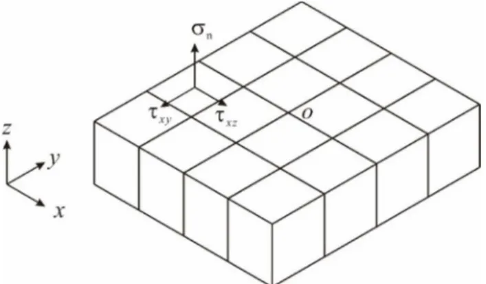
According to the force characteristics of pile foundation, the bridge piles embedded in bedrock can be regarded as cantilever beams fixed at one end. Selecting any horizontal cross-section of the pile as the object to study, and provides xoy plane established in the cross-section, z axis established
Figure 1. Pile cross section stress diagram.
as axis direction, as shown in Figure 1. Therefore the normal unit vector of the cross section is v = (0, 0, 1). According to Eq. (2), the stress on this surface is
0 0 1 = =
x xy xz xz
xy y yz yz
xz yz z z
X Y Z σ τ τ τ τ σ τ τ τ τ σ σ (3)
The internal force of the pile is calculated as follows:
=
∫
=∑
in z i
i A
,
=
∫
=∑
ix xz i xz i
i A
T τ dA τ A (5)
,
=
∫
=∑
iy yz i yz i
i A
T τ dA τ A (6)
=
∫
ix z c i
A
M σ y A (7)
=
∫
iy z c i
A
M σ x A (8)
Where, N: Pile body axial force;
Tx, Ty: the shear force of Pile section along the x axis and y
axis;
Mx, My: the bending moment of the pile section around the
x-axis and the y-axis;
Ai: the area of the unit cross section
xc, yc: the component of the distance between the unit
centroid and the pile on the x-axis and the y-axis, respectively.
3. Engineering Example
3.1. Engineering Background
Taking the pile foundation of the left bank of Dahua Bridge as the engineering background, the numerical analysis
of pile-soil interaction was carried out. Dahua Bridge is a connecting bridge between Huanglong dam concentration and left bank along the river, located at about 20km upstream of Dahuaqiao Hydropower Station. The main bridge is a prestressed concrete continuous rigid frame bridge. Approach Bridge is a mounted reinforced concrete T - shaped girder bridge. The left bank of the bridge site is Dahua deposit body. Five piers are laid out there, which is Pile 2, Pile 3, Pile 4, Pile 5 and Pile 6 respectively. Pile foundation is artificial digging pile, and pile top is embedded in bedrock. C50 concrete is used in bridge pier bearing and C35 concrete. is used in pile foundation. In order to ensure the stability of the deposit body at the bridge site, nine anti-slide piles are arranged between Pile 2 and Pile 3. The concrete slabs are arranged in front of the piles to form the sheet pile wall to increase their overall rigidity to bear the slope Landslide thrust transmitted from upper soil.
3.2. Numerical Model and Material Parameters
The load of the piers acting on the platform under three different working conditions is shown in table 1.
According to the geological survey data, the surface layer of Dahua deposit body is Q4 loose overburden, and the underlying bedrock is Jurassic (J) purple shale and slate. The pile foundation of the bridge is weakly weathered bedrock, and the physical and mechanical parameters of the geotechnical materials are shown in the table 2.
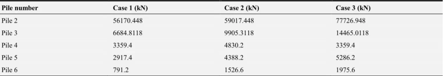
Table 1. Load design value of bridge piers on pile-cap under different operating conditions.
Pile number Case 1 (kN) Case 2 (kN) Case 3 (kN)
Pile 2 56170.448 59017.448 77726.948
Pile 3 6684.8118 9905.3118 14465.0118
Pile 4 3359.4 4830.2 3359.4
Pile 5 2917.4 4388.2 5286.2
Pile 6 791.2 1526.6 1975.6
Table 2. Material parameters of Dahuaqiao deposit body.
Material type Friction angle φ(°°°°)
Cohesion
c(kPa)
Deformation modulus
E(GPa)
Poisson ratio
µµµµ Dry unit weight γγγγ (kN/m3)
Saturated unit weight γγγγsat(kN/m3)
overburden above water 26 35 2.0 0.30 21 22
under water 23 15 1.6 0.34
strong weathered bedrock 33 750 10 0.2 26.6 26.8
weak weathered bedrock 40 2000 30 0.15 27.0 27.2
concrete (bridge pile foundation) 45 1000 25 0.2 25.0 25.0
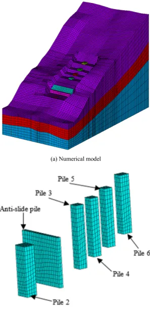
In order to eliminate the influence of boundary on the calculation results, the model range is as follows: the width across the river is 170m, the length along the river is 310m, the maximum height is 210m. There are 130,378 nodes and 163,867 elements in the numerical model. The mesh is mainly composed of the hexagonal elements. Bridge piles and anti-slide piles are modelled by solid elements, and the contact elements are set between the pile and soil, as show in Figure 2.
(a) Numerical model
(b) model mesh of pile
Figure 2. Schematic diagram of model mesh.
3.3. Calculation Results and Analysis
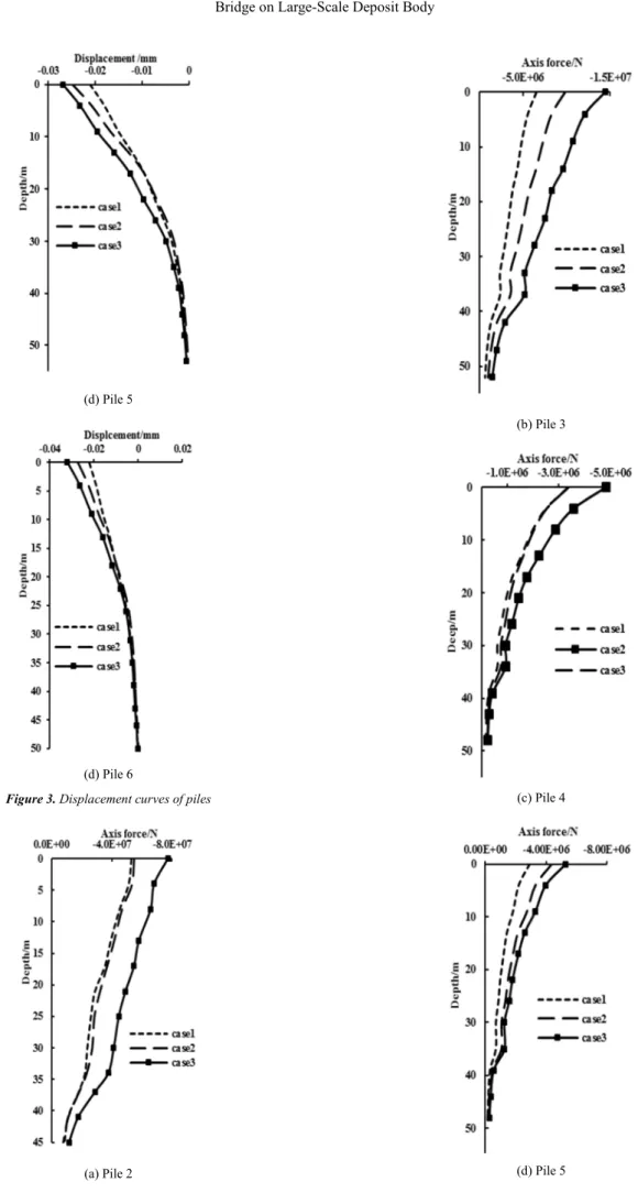
The numerical analysis was carried out in the completion period, after slope excavation and bridge construction were completed. Figure 3 shows the distribution of pile displacement in different positions under three different load conditions. As can be seen from Figure 3, the displacement of different positions of the pile are different, but the overall trend is consistent under three different load conditions. For Pile 2, there is a dividing line in the range of 20m∼30m from the pile top. At the upper part of the dividing line, the upper part of the pile is moved downward and the low part is moved upward. The displacement of the pile top is about 4 cm, indicating that there is a potential slip surface at the dividing line. For Pile 3∼Pile 6, the displacement along the pile has a tendency to decrease gradually. The displacement at the top of the pile is about 3 cm~4 cm, and at the pile end tends to 0, the displacement curve does not have the mutation phenomenon. It is indicating that the anti-slide pile has played a significant anti-sliding effect.
(a) Pile 2
(b) Pile 3
(d) Pile 5
(d) Pile 6
Figure 3. Displacement curves of piles
(a) Pile 2
(b) Pile 3
(c) Pile 4
(d) Pile 6
Figure 4. Axis force curves of piles.
The distribution curves of the pile axial force along the pile in different positions under different load conditions are shown in Figure 4. It can be seen that the pile foundation at different positions is generally reduced along the pile depth, but it is significantly different in the trend of decreasing the axial force at different depth. There is a clear boundary in the depth of 30m~40m. The axial force at the upper part of the interface is reduced slowly and is fast at the lower part. Combining the geological profile, we can find that the interface is consistent with the foundation-cover boundary of each pile foundation. The reason is that the pile side friction force is not the same as that provided by the different types of soils, and the pile side friction force provided by the strong weathered rock is significantly larger than that of the upper part of the deposit body. In addition, the pile side friction force has been fully used, as a result that the rock at pile end bear small resistance.
(a) Pile 2
(b) Pile 3
(c) Pile 4
(e) Pile 6
Figure 5. Shear force curves of piles.
(a) Pile 2
(b) Pile 3
(c) Pile 4
(d) Pile 5
(e) Pile 6
The Figure 5 and Figure 6 shows the distribution of the shear and bending moments of the pile at different positions under three different combinations of conditions. It can be concluded that the shear force along the pile depth has a trend that increased first and fall later. There is a clear boundary at about 25m from the top of the pile. In addition, the distribution of pile shear is very close under the three different load conditions. The reason is that the shear force of the pile is mainly affected by the sliding force of the deposit body along the slope.
Under different load conditions, the bending moment distribution of Pile 2 has the tendency of increasing first and decreasing later, and Pile 3~Pile 6 have the tendency of increasing first, decreasing later and then increasing again. In addition, the bending moment of pile 2 is obviously smaller than the other pile, and the bending moment of pile foundation in different positions increases with the rising elevation. The reason is that the deformation of the deposit body has obvious characteristics of the thrust-type, which is caused by large deformation of the upper part. A row of anti-slide piles arranged between pile 2 and pile 3 prevents the further deformation of the deposit body, so that pile 2 is subjected to a smaller bending moment. It is further demonstrated that the reinforcement effect of anti-slide pile is remarkable.
4. Conclusions
1. The method has been developed to calculate the internal force of piles when the pile is simulated with solid elements and the contact surface is simulated with interface elements. It is proved that the numerical solution has a good agreement with the theoretical solution through a cantilever beam example.
2. The pile foundation at the left bank bridge of Dahuaqiao has been simulated using FLAC3D. The result shows that, the axial force distribution along the pile in different positions is gradually decreasing with the increase in depth, and the decreasing amplitude is different in different soils. The distribution rules of the displacement, shear force and bending moments of Pile 3~Pile 6 are basically same, and has a significant difference with Pile 2 due to the anti-slide pile. The result indicate that the anti-slide pile reinforcement effect is remarkable.
Acknowledgements
This work is supported by the National key research and development project (2016YFC0401801 and 2016YFC04018 04), Natural Science Foundation of China (Grant No. 51674058).
References
[1] Ito T, Matsui T, Hong W P. Design Method for the Stability Analysis of the Slope with Landing Pier [J]. Journal of the Japanese Society of Soil Mechanics & Foundation Engineering, 1979, 19(4):43-57
[2] Yu Yuzhen, Deng Lijun. Centrifuge modelling of seismic behavior of slopes reinforced by stabilizing pile[J]. Chinese Journal of Geotechnical Engineering, 2007, 29(9):1320-1323. (In Chinese)
[3] Li Shaojun, KNAPPETT J A, Feng Xiating et al. Centrifugal tests on slope reinforcement by anti-sliding piles modelling change of reservoir water level[J]. Chinese Journal of Rock Mechanics and Engineering, 2009, 28(5):939-946. (In Chinese)
[4] Wang Liping, Zhang Ga, Zhang jianming et al. Centrifuge modeling of cohesive soil slopes reinforced by stabilizing piles[J]. Chinese Journal of Geotechnical Engineering, 2009, 31(7):1075-1081. (In Chinese)
[5] Li Tianbin, Tian Xiaoli, Han Wenxi et al. Centrifugal model tests on sliding failure of a pile-stabilized high fill slope[J]. Rock and soil Mechanics, 2013(11):3061-3070. (In Chinese) [6] Poulos H G. Analysis of piles in soil undergoing lateral
movement[J]. Journal of Soil Mechanics & Foundations Div, 1973, 99:391-406.
[7] Zhao Minghua, Wu Longgang, Liu Jianhua. Inner-force and displacement analysis of load-bearing and anti-slide piles by p-y curve method[J]. Chinese Rock Mechanics and Engineering, 2007, 26(6):1220-1225. (In Chinese)
[8] Zhang Aijun, Mo Haihong, Zhu Zhende et al. Analytical solution to interaction between passive and soils[J]. Chinese Journal of Geotechnical Engineering, 2011, 33(s2):120-127. (In Chinese)
[9] Ye Xiaoming, Wang Zhen, Yu Fei. Study on calculation method of anchored stabilizing piles based on displacement of soil around piles[J]. Chinese Rock Mechanics and Engineering, 2016(a01):3187-3194. (In Chinese)
[10] Kourkoulis R, Gelagoti F, Anastasopoulos I, et al. Slope Stabilizing Piles and Pile-Groups: Parametric Study and Design Insights [J]. Journal of Geotechnical & Geoenvironmental Engineering, 2010, 137(7):663-677. [11] Yang S, Ren X, Zhang J. Study on embedded length of piles for
slope reinforced with one row of piles [J]. Journal of Rock Mechanics and Geotechnical Engineering, 2011,
03(2):167-178. (in Chinese)
[12] Nian Tingkai, Xu Haiyang, Liu hongshuai. Several issues in Three-dimensional numerical analysis of slopes reinforced with anti-slide piles[J]. Rock and Soil Mechanics, 2012, 33(8):002521-2535. (In Chinese)
[13] Dai Zihang, Xu Xiang. 3D finite element method for design computations of anti-slide piles[J]. Chinese Journal of Rock Mechanics and Engineering, 2012, 31(12):2572-2578. (In Chinese)
[14] Wang Xinggang, Hu Bin, Lian Baoqin et al. 3D analysis of interaction of landslide and anti-slide pile system under sudden change of reservoir water level[J]. Chinese Journal of Rock Machanics and Engineering, 2013, 32(12):2439-2446. (In Chinese)
[16] Liu Jianhua, Zhao Minghua, Yang Minghui. Model tests on bridge pile foundation in high and steep rock slopes[J]. Chinese Journal of Geotechnical Engineering, 2009, 31(3):372-377. (in Chinese)
[17] Gong Xianbing, Yang Minghui, Zhao Minghua et al. Load-bearing Mechanism model test for bridge pile foundation in high-steep transverse slope[J]. China Journal of highway and transport, 2013, 26(2):56-62. (in Chinese)
[18] Zhang Yongliang, Chen Xingchong, Sun Jianfei. Nonlinear static calculation model and pseudo-static test of pile group bridge foundation[J]. Chinese Journal of Rock Mechanics and Engineering, 2013, 32(9):1799-1806. (in Chinese)
[19] Ning Xiayuan, Yin Pingbao, Xie Shangfei. The design and calculation method and its applications of bridge piles in steep cross slopes[J]. Highway Engineering, 2012, 37(4):56-61. (in Chinese)
[20] Wu Guanxiong. Stress and deformation analysis of Liangjiang grand bridge pile foundation in Xinxu highway[J]. Highway Engineering, 2013, 38(3):119-122. (in Chinese)
[21] Zhao Minghua, Yin Pingbao, Yang Minghui. Analysis of influence factors and mechanical characteristic of bridge piles in high and steep slopes[J]. Journal of Central South University (Science and Technology), 2012, 43(7):2733-2739. (in Chinese)