Published online October 16, 2014 (http://www.sciencepublishinggroup.com/j/ijmea) doi: 10.11648/j.ijmea.s.2015030101.14
ISSN: 2330-023X (Print); ISSN: 2330-0248 (Online)
Air conditioning and application
Karel Adamek
1, Jan Kolar
1, Pavel Peukert
1, Marek Kaspar
21VÚTS – Centre of Machinery Research, Liberec, Czech Rep 2GEA - Heat Exchangers, Liberec, Czech Rep
Email address:
[email protected] (K. Adamek), [email protected] (J. Kolar), [email protected] (P. Peukert), [email protected] (M. Kaspar)
To cite this article:
Karel Adamek, Jan Kolar, Pavel Peukert, Marek Kaspar. Air Conditioning and Application. International Journal of Mechanical Engineering
and Applications. Special Issue: Moving Forward to Monitory Democracy: Citizens Engagement in Scrutinizing Election Process in
Indonesian 2014 General Election. Vol. 3, No. 1-1, 2015, pp. 22-27. doi: 10.11648/j.ijmea.s.2015030101.14
Abstract:
The contribution summarizes some interesting results received at flow numerical simulations in various parts of systems for air conditioning, as for instance heating and transporting, used – not only - in various textile technologies. The correct air temperature and humidity are necessary conditions for reliable and economic treatment of textile materials in general. Actual use of renewable energy is discussed, too.Keywords:
Numerical Flow Simulation, Heat Exchange, Clean Rooms, Exhausting1. Introduction
Many technologies need some parameters of surrounding air to get reliable and effective production. For this purpose, the air conditioning system is used, containing typically heat exchangers, inlets / outlets, fans, filtering, etc. Several solved cases are presented in the following text, first of all, as a presentation of the actual state and possible increasing of parameters.
2. Devices for Air Conditioning Systems
From many existing devices and equipment for air conditioning for various purposes in technical practice there are chosen some of them, only, as suitable examples of the use of flow numerical modeling.
2.1. Flue Gases Air Heater
The aim of this numerical simulation is to determine the temperature field in flue air heater and by suitable adjustments to suppress local overheating, first of all, in the first bend of the flue way between the flame tube and the first set of reverse tubes. In Fig. 2.1-1, there is the temperature field in the lengthwise cross section with maximum values in the lower flame tube. In the subsequent passages, the temperature is decreasing to the outlet, the air temperature around tubes is lower in general.
The next Fig. 2.1-2 presents the velocity field in the cross section. The highest velocity value is in the third passage, where the second passage of 3 tubes is transformed into the third passage of 2 tubes, only. Well staggered tubes are not mutually blocked.
Figure 2.1-1. Temperature of flue gases in lengthwise cross section of air
heater
In Fig. 2.1-3, there is the surface temperature of flue heat exchanger, the highest values are on the first side reverse chamber between the flame tube and the first set of tubes. It is necessary to verify yet if such local overheating is not given by an unsuitable shape of mesh elements.
Figure 2.1-3. Surface temperature of heat exchanger
Fig. 2.1-4 shows the streamlines field colored by the temperature (in the range 300 – 320 K) for the design with 3 rows of tubes for the next discussion about the progress of the solution. Comparing with Fig. 2.1-2 above, it seems that the area of tube is better filled so that it is possible to expect better heat exchange.
Figure 2.1-4. Streamlines in the 3-rows heat exchanger, colored by
temperature
2.2. Laminar Ceiling
The so-called laminar ceiling is in principle the air inlet into the volume under the ceiling of a room, from where the air is outgoing through the filtering layer in the working area (for instance the surgical table, working area in pharmacy and similar clean areas). For various arrangements of the inlet and outlet, after the building disposition, it is necessary to provide the most uniform air flow from the so-called laminar ceiling into the whole ground plan under this ceiling. It is possible to use the received knowledge for preparation of designing data for various typical arrangements of air inlets.
As an illustration, Fig. 2.2-1 and Fig. 2.2-2 present streamlines field in both front view and ground plan for one case of air inlet over the laminar ceiling. In the area under ceiling, there is a very complicated streamlines field, which is
perfectly aligned just in the laminar ceiling.
Figure 2.2-1. Laminar ceiling - streamlines in the front view
Figure 2.2-2. Laminar ceiling - streamlines in the ground plan
The next Fig. 2.2-3 presents the streamlines at an angle of attack 30° toward the filtering layer, created as folded filtering paper in Z-shape.
Figure 2.2-3. Streamlines at angle of attack are aligned into the direction
perpendicular to the filtering layer
Figure 2.2-4. Details of the pressure field at bends of paper filter on both
The detail of the pressure field at the tip of such Z-bend of folded paper filter at leading edge is presented in Fig. 2.2-4 left and the pressure field in the tip of Z-bend at the trailing edge is presented in Fig. 2.2-4 right.
2.3. Air Shower
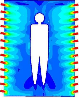
A numerical model solves the influence of a set of air flows on the person who is entering into the so-called clean area. In Fig. 2.3-1, there is the velocity field of such a set of nozzles, in Fig. 2.3-2, there is the field of dynamic pressure on the surface of the dummy. For completion, Fig. 2.3-3 presents the cross-section at the legs and head levels, for a possible more detailed analysis of the flow influence.
Figure 2.3-1. Velocity field from set of nozzles
Figure 2.3-2. Dynamic pressure on the dummy surface
Figure 2.3-3. Velocity fields at levels of legs and head
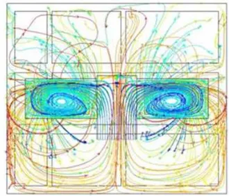
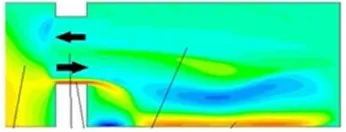
2.4. Air Flow in Air Conditioning Unit
The results of numerical modeling of the flow in a standard console air conditioner show that individual tubes of the heater are not flowed uniformly, therefore, their heat output is not uniform, too, see the pressure and velocity field in Fig. 2.4-1.
Figure 2.4-1. Pressure (left) and velocity (right) fields
For thermal output increasing or for outlines of unit decreasing, the air flow should be better aligned in such a manner to get a more uniform flow.
In the following complex solution, the influence of uneven air outlet from the installed radial fan on the range of the free flow into the surroundings was observed, too. The results were verified by experiment with a satisfactory coincidence.
2.5. Air Curtain
In many cases (stocks, stores), it is necessary to prevent the inlet of cold outer air over the open gate into the inner space by flow of a warm curtain air flow. The disturbing flow arises by wind effect or by internal suction devices. The following figures of flow fields present temperature fields in the solved area because temperatures are here more contrast comparing to very small velocity values. The left outer temperature is the smallest, the temperature of the curtain flow from up is the highest. The following figures show a serial of typical cases of interaction between curtain and outer flow.
and the curtain flow is off.
Figure 2.5-1. Temperature field – disturbing flow, only
The next situation in Fig. 2.5-2 presents the second boundary case when the curtain air is on, without disturbing flow.
Figure 2.5-2. Temperature field – curtain flow, only
The third case in Fig 2.5-3 shows the suitable combination of disturbing and curtain flows, when the installed air curtain is able to stop the disturbing flow at a defined intensity.
Figure 2.5-3. Temperature field – suitable operational combination of both
curtain and disturbing flows
And the last case Fig. 2.5-4 shows similar situation, but the level of disturbing flow is higher than in the previous case and curtain flow is not able to keep back it out – some part of the cold air if flowing in into the protected area. This last case is not suitable for practical use.
Figure 2.5-4. Temperature field – unsuitable situation, disturbing flow is too
intense
The presented good qualitative image about the flow field in the vicinity of the curtain flow is possible to complete by a quantification of the heat balance in the opening between two areas of different temperatures, separated by the curtain flow [2]. In each element of the calculation mesh, all parameters of the flow are well-known – dimensions, velocity components, temperature, density, etc. The thermal loss or profit is equivalent to the product of mass flow through the observed mesh element and of temperature difference between the mesh element temperature and the referencing temperature, defined usually as the inner temperature. Both factors can have a
positive or negative value so that we receive four possible combinations. Two of them are positive (thermal gain), two are negative (thermal loss). By a subsequent solution of several cases with an increasing intensity of the disturbing flow, the initial positive value is changed on the negative one. Such a case is the limiting case for practical use of the solved curtain flow in the given opening.
3. Thermal Insulation
In general, thermal insulation is necessary for suppression of thermal losses and so for increasing of efficiency of operating systems. Only few examples are presented here for illustration.
3.1. Not Insulated Surface
Not insulated surfaces of the tube or fixtures are the sources of thermal losses. The next Fig. 3.1-1 shows the temperature field (left) and the directional field (right) around such a not insulated tube.
Figure 3.1-1. Flow around hot tube
The heated air is flowing up and the heat exchange - heat loss - by convection is increasing.
Warmed air is flowing up and increased velocity intensifies the thermal loss by convection.
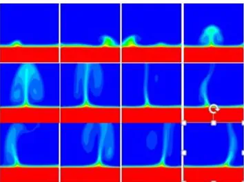
3.2. Hot Surface
A serial of temperature fields presents the time-depending arising and development of a warm air bubble on the horizontal heated surface – see Fig. 3.2-1, row by row. The warm air area is first arising, then increasing until its separation, then remains a warm trace, in which repeatedly arises more or less intensive stream of warm air.
3.3. Wall Thermal Insulation
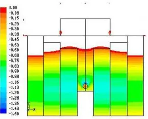
Here is presented a numerical simulation of the thermally insulated wall. Fig. 3.3-1 presents the original state with following modeled temperatures: 300 K (27°C, red) in the room, outside 260 K (-13°C, blue) and 278 K (+5°C, green) in the area without basement under the room. It is visible the standard temperature gradient in the defined structure, in the corner of the room, the temperature is locally decreased – here is the danger of the air humidity condensation.
Figure 3.3-1. Temperature field in building structure- no insulation
With an added thermal insulation layer on the front face of the wall after Fig. 3.3-2, there is visible some temperature increasing in the structure and some small temperature increasing in the cold corner. But it is visible, too, that the lower edge of the insulation should be shifted lower, under the level of deck of lower living floor. The thermal insulation of the ground floor area is not sufficient.
Figure 3.3-2. Temperature field in building structure - outer insulation
added
When the inner wall temperature is decreasing under the dew point temperature of inner air, the air humidity is condensing on the cold wall surface. Insufficiently insulated walls are often the reason of practical and hygienic problems, as for instance wet or mouldy wall structure, etc. The moisture condensation can be prevented by sufficient aerating, too, see Fig. 3.3-3.
Figure 3.3-3. Velocity field in room – window fully open
Opening the window, the cold and dry outer air (from the left) is flowing in the room down, pushing, at the same time, the warm and wet inner air up and out (down to the right and back up to the left). In such a manner, the air volume of the whole room is exchanged quickly, wet inner air is substituted by the dry outer one. Due to a relative small value of heat capacity, the cold air is quickly heated at the original temperature. The air moisture is low, the dew point is low, too.
When the wall temperature remains over the dew point, the problem of wet wall surfaces is removed. Of course, small window opening, only, has not practically any effect.
3.4. Solar Ventilating
The example of simple, reliable and free of operating expenses system for ventilating and tempering of living and processing areas [3]. In the classical window frame, there is inserted the inner absorber, warmed-up by solar radiation and both air inlet and outlet are added. During the solar irradiation, the absorber is warmed-up and from it there is warmed the air, flowing around the absorber surface due to a small fan, driven by solar cell. This effect is used for ventilating and tempering of uninhabited rooms, for an inhabited room, the heating period is shortened.
Figure 3.4-1. Temperature (left) and pressure (right) field in solar panel
vertical cross-section)
Fig. 3.4-1 (left side) shows the temperature field in the cross section of the panel – from the left side, the solar radiation is going through the covering glass onto the middle surface – the warmest part – the warming air is raising up. The covering glass is defined as thermal insulated, really there is some warming-up, too. In the right channel, the warmed air is going down again to the outlet and is warmed again from the absorber, the outer (right) side is thermally insulated. On the right side, there is the relevant pressure field – the pressure is decreasing from the value in the surroundings (left) onto the under pressure in the fan suction at the outlet.
Figure 3.4-2. Temperature field of large facade system.
The system can be applied on wide facade surfaces, too, and then it is better to use the fan driven from the mains. Fig. 3.4-2 shows the temperature distribution on the facade of 7x5 m2 (common outlet down in the middle).
Figure 3.4-3. Temperature field in summer mode – exhaust by chimney effect
Figure 3.4-4. Under pressure area in summer mode – exhaust by chimney
effect
In Fig. 3.4-4, it is showed the area of under pressure, only, in such a system (suppressed scale). It is visible that in the inlet into the room (down in the middle) there is the under pressure, it means that when the fan is off, it is possible to exhaust the air from the inner space of the building by the natural chimney effect.
References
[1] J. Kolar, K. Adamek,"Permeability of folded filter", Strutex - 15th Int. Conf. Structure and Structural Mechanics of Textiles, TU Liberec, 2008. ISBN 978-80-7372-664-5.
[2] K. Adamek, "Usability range of air curtain for gate", Finite elements methods (2000), 49-55, ÚT CAV Praha, ISBN 85-85918-60-9–350 (in Czech).