ISSN (Online): 2320-9364, ISSN (Print): 2320-9356
www.ijres.org Volume 5 Issue 8 ǁ August. 2017 ǁ PP. 32-39
Effect of Liquid Viscosity on Sloshing in A Rectangular Tank
*
Eiji Suzuki
(Department of Mechanical Engineering, Oyama National College of Technology, 771 Nakakuki, Oyama 323-0806, Japan)
Corresponding author*Dwinik Winawangsari1
ABSTRACT :
Liquid sloshing was investigated for a moving partially filled rectangular tank with/without vertical baffles. A set of experiments was conducted using two types of liquids: water and sunflower oil. For these liquids, the effects of varying the external excitation amplitude and the number of vertical baffles on sloshing are discussed. It was found that the mechanical dissipation due to the liquid viscosity has a remarkable influence on the sloshing characteristics.Keywords:
sloshing, viscosity, baffle,hysteresis, particle image velocimetryI.
INTRODUCTION
Liquid sloshing is of significance in flow physics and in a wide range of applications such as liquid- carrying vehicles, space vehicles, and cargo ships. Many types of liquids such as water, oil, and liquefied natural gas are used in these applications. Fluid motion in a tank partially filled with liquid can impose large structural loads if the period of the tank motion is close to the natural period of the fluid inside the tank. A variety of investigations of sloshing has been studied numerically and experimentally over the past few decades, and these studies have explored significant phenomena such as the linear and nonlinear sloshing effects of the sloshing wave. Early analyses of sloshing were simply linear, weakly nonlinear and inviscid analyses [1]. In the years following 1990, fully nonlinear free surface boundary conditions, complete primitive Navier-Stokes equations, and fluid viscosity have also been considered in the published studies. Baffles are efficient inner structures for suppressing resonant sloshing. Wu et al. numerically predicted the effect of bottom-mounted vertical baffles on liquid sloshing in a rectangular tank and observed vortex shedding near the baffle tip [2]. Various experiments have been carried out to estimate the pressure on the tank walls and the free surface displacement of water from a mean static level. Akyildiz et al. experimentally investigated the pressure distribution in a tank with baffles and concluded that baffles significantly reduce the fluid motion [3]. Zou et al. experimentally investigated the effect of viscosity on sloshing in a tank without baffles and showed that the viscosity of the liquid has an important effect on the sloshing pressure [4].
To reduce the damage caused by the sloshing, many studies of sloshing have been conducted with water as the working fluid. On the other hand, the effects of viscosities of liquids other than water on sloshing are rarely reported. Many works have been devoted to the investigation of the effect of baffles on reducing the sloshing effects. However, the mechanism whereby sloshing due to the baffles and liquid viscosity is damped is not fully understood. In the present study, the effects of varying the external excitation amplitude and the number of vertical baffles on sloshing in a rectangular tank were examined both experimentally and numerically. The vertical baffles are fixed to the bottom of a tank, which is excited with a given excitation frequency. To investigate effects of the viscosity of the liquid, two fluids are considered: water and sunflower oil. Section Ⅱ introduces the experimental method. Section Ⅲ describes the numerical and experimental results, and Section Ⅳpresents the concluding remarks.
II.
EXPERIMENTAL
APPARATUS
AND
PROCEDURE
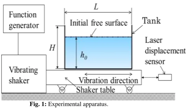
In this study, a rectangular tank partially filled with liquid was actuated by a sinusoidal vibrating shaker table. Fig. 1 shows a schematic view of the experimental setup that consisted of a function generator, vibrating shaker, shaker table, tank, and laser displacement sensor. The dimensions of the tanks with/without the baffles were the same, being 310 mm in length (L), 240 mm in height (H), and 140 mm in width. The still water depth
Fig. 1: Experimental apparatus.
Two types of liquids were considered in this study, in order to investigate the effect of the viscosity on sloshing. The first liquid is water. The second is sunflower oil, which is 50 times more viscous than water. Table 1 lists the physical properties of the two liquids. These liquids can be considered Newtonian over the temperature range that we examined. All experiments were conducted at room temperature (22°C ±3°C) and under atmospheric pressure.
Table 1: Physical properties of liquids: ρ = density, μ = dynamic viscosity, ν = kinematic viscosity,
σ = surface tension.
ρ (kg·m-3) μ (Pa·s) ν (m2·s-1) σ (N·m-1)
Water 998 8.94×10⁻⁴ 8.96×10⁻⁷ 0.072
Sunflower oil 900 0.045 5×10⁻⁵ 0.033
Planar two-dimensional particle image velocimetry (PIV) was used to determine the U and V velocities in water. Spherical particles made of a synthetic polymer with an average diameter of 90 μm and a density of 1010 kg/m3 were used as tracer particles for the PIV measurement. A light sheet formed by a continuous YAG laser (wavelength: 532 nm) was used to illuminate the particles seeded in the tank. The positions of the particles were recorded using a high-speed digital video camera, operating at 1000 frames per second (fps) in this study. FlowExpert, a commercial PIV software, was used to measure the two-dimensional time-dependent velocity fields. A high-speed digital video camera was used to capture the free surface motion of the liquid.
III.
RESULTS
AND
DISCUSSION
3.1 Sloshing in Rectangular Tank without Baffles
The free surface elevation η is highly dependent on the amplitude and forcing frequency of the tank motion, liquid depth, liquid properties, and tank geometry, where η = h - h0 and h is the water depth. The natural frequencies of the sloshing response in a rectangular tank without baffles can be calculated by using the following equation [5]:
ωn2 = gkntanh(knh0), kn= (2n-1)π/L, n = 1,2,3, ···.(1)
entire procedure, the tank was continually subjected to forcing and the excitation amplitude was held constant; only the excitation frequencies were changed incrementally.
Fig. 2 shows the frequency response of the free surface elevation at the right wall in an unbaffled tank for water and the oil when h0 = 50 mm and Ae= 0.5 mm. Arrows in this figure show the directions of frequency increase and frequency decrease. When the tank is filled with water, the free surface elevation changes drastically at an excitation frequency of around 1.08 Hz, regardless of whether the frequency is increasing or decreasing. The hysteresis behavior can be clearly observed under this experimental condition. The hysteresis in the sloshing of shallow water in a horizontally excited tank was explored experimentally [6]. On the other hand, the free surface elevation in the tank filled with the oil is extremely low compared to that filled with water. Energy dissipation due to viscous friction leads to a reduction in the wave elevation.
Fig.2: Free surface elevation as a function of excitation frequency at right wall of tank without baffle when h0 = 50 mm and Ae = 0.5 mm in the cases with water and the oil. The solid circles indicate an increase in the frequency while the open circles indicate a decrease in the frequency in the case of water. The triangles indicate an increase and a decrease in the frequency for the oil.
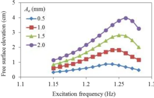
Fig. 3 shows the frequency response of the free surface elevation at the right wall of an unbaffled tank for the oil when h0 = 70 mm. It can be seen that no hysteresis is observed under different excitation amplitudes (Ae = 0.5, 1.0, 1.5, and 2 mm) and as the excitation amplitudes increases, the corresponding resonant frequency increases accordingly.
Fig.3: Free surface elevation as a function of frequency at right wall of tank without baffles for different
excitation amplitudes when h0 = 70 mm (with the oil).
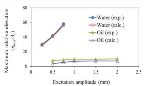
than that obtained with water. When the liquid viscosity increases, the damping effect due to mechanical dissipation is more significant. In addition to the experimental results, the numerical results are also plotted in Fig.4. The numerical simulation was carried out by using OpenFoam [7]. The physical properties of liquids used in the numerical simulation are listed in Table 1. The numerical results are identical to those obtained by experiment in the case of water. On the other hand, the numerical results are slightly lower than the experimental ones in the case of the oil.
Fig.4: Maximum relative free surface elevation as a function of excitation amplitude at right wall of tank
without baffle when h0 = 70 mm (for water and the oil).
3.2 Sloshing in Rectangular Tank with Baffles
This section discusses the effects of the number of baffles on liquid sloshing in a rectangular tank. Sketches of the baffle arrangements are shown in Fig. 5. For every case considered in this study, the dimensions of the baffles are all the same, that is, 15 mm in height (hB) and 140 mm in width. The width of the baffles is equal to that of the tanks. All of the baffles are attached vertically to the bottom and are assumed to be rigid. The
x-y Cartesian coordinates are fixed to the tank and the origin of the coordinates is set at the center of the bottom of the tank.
Fig.5: Baffle arrangements (Units: mm).
Fig. 6 shows the free surface elevation in the tank with/without baffles as a function of the excitation frequency when h0 = 70 mm and Ae = 2 mm. As shown in Fig. 6, the maximum free surface elevation in the tank with baffles is lower than that of the tank without baffles. Furthermore, it can be observed that the resonant frequency in the tank with baffles is smaller than that in the tank without baffles.
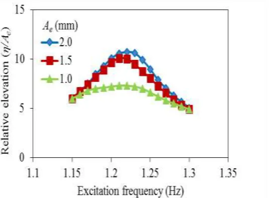
Fig. 7 shows the relative free surface elevation as a function of the excitation frequency in a tank with a single baffle at different excitation amplitudes for the oil. As is shown in Fig. 7, it can be seen that the resonant frequency is hardly affected by the excitation amplitude. In contrast, the relative elevation around the resonant frequency is greatly influenced by the excitation amplitude. Furthermore, it seems that the relationship between the excitation amplitude and relative elevation is nonlinear.
x
y
x =
0
h
B(
a
) Single baffle
Baffle
x = -60
x = 60
(a) Single baffle
(b) Two baffles
x = -60
x = 0
x = 60
(b) Two baffles
Fig. 6: Free surface elevation as a function of excitation frequency at right wall with/without baffles when h0 = 70 mm and Ae = 2 mm (with the oil).
Fig.7: Relative free surface elevation as a function of excitation frequency at right wall of tank with single
baffle under different excitation amplitudes when h0 = 70 mm (with the oil).
Fig.8: Relative free surface elevation as a function of excitation amplitude with different numbers of baffles when h0 = 50 mm and Ae = 2 mm (for water).
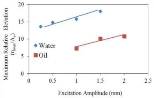
Fig. 9 shows the relative maximum free surface elevation as a function of the excitation amplitude at the right wall of a tank with a single baffle when h0 = 70 mm for both water and the oil. It can be observed that the relative maximum surface elevation increases almost linearly over the measured range of the excitation frequency.
Fig.9: Relative maximum free surface elevation as a function of excitation amplitude at right wall of tank with
single baffle when h0 = 70 mm (both water and the oil).
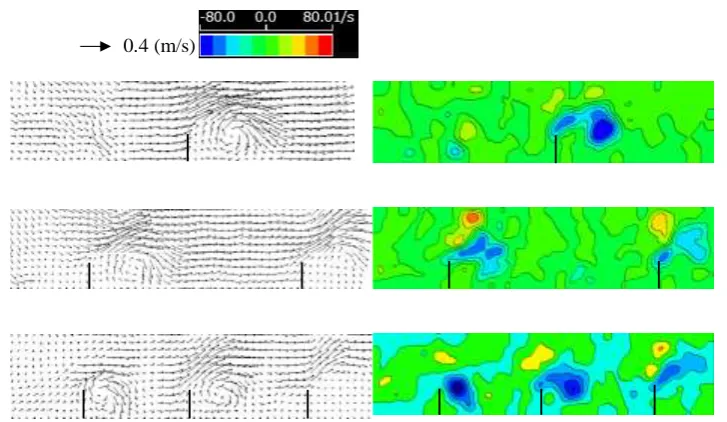
Fig. 10: Velocity vectors (left) and vorticity contours (right) obtained by PIV in the vicinity of baffles at T/4 when h0 = 60 mm, ωe = 7.5 rad/s, and Ae = 2 mm (with water).
The vorticity contour in a tank with three baffles, obtained numerically using OpenFoam, is depicted in Fig. 11 under the same operating conditions as those shown in Fig. 10. It can be seen that the numerically obtained vorticity contour shown in Fig. 11 is slightly different from that obtained experimentally and shown in Fig. 10. Strong shear layers are formed on the bottom of the tank, as shown in Fig. 11.
Units: 1/s
Fig. 11: Vorticity contour obtained numerically by OpenFoam in the vicinity of the baffles at T/4 when h0 = 60
mm, ωe = 7.5 rad/s, and Ae = 2 mm.
IV.
CONCLUSIONS
The objective of this study was to investigate, experimentally and numerically, the effect of liquid viscosity on sloshing in a tank with/without vertical baffles. In particular, the wave response near the resonant frequency was investigated using water and sunflower oil.
Some of conclusions can be summarized as follows:
(1) By incrementally increasing or decreasing the excitation frequency, hysteresis phenomena were observed near the resonance frequency in the experiment with water. They were not with the sunflower oil.
(2) With an increase in the excitation amplitudes, the corresponding resonant frequency increases accordingly in a rectangular tank with/without baffles in the case of sunflower oil.
(3) The maximum free surface elevation decreases as the number of baffles increases.
(4) The relative maximum surface elevation increases almost linearly over the excitation frequency measured in a rectangular tank with a single baffle.
(5) The velocities in a rectangular tank with/without baffles were measured by using particle image velocimetry (PIV) in the case of water. It was observed that stronger vortices occurred in the neighborhood of the baffles in the tank as the number of baffles was decreased.
(6) The numerical results show that strong shear layers are formed at the bottom of the tank.
A
CKNOWLEDGEMENTSI would like to express my gratitude to Mr. MasatakaAkada for his help with this experiment.
REFERENCES
[1]. T. Nakayama, and K. Washizu, Nonlinear analysis of liquid motion in a container subjected to forced pithing oscillation, International Journal for Numerical Methods in Engineering, 15( 8), 1980,1207-1220. [2]. C. H. Wu, O.M. Faltinsen, and B. F. Chen, Numerical study of sloshing liquid in tanks with baffles by
time-independent finite difference and fictitious cell method, Computers & Fluids, 63,2012, 9-26. [3]. H. Akyldiz, N. E. Unal, and H. Aksoy, An experimental investigation of the ring baffles on liquid
sloshing in a rigid cylindrical tank, Ocean Engineering, 59,2013, 190-197.
[4]. C.H. Zou, D.Y. Wang, Z.H. Cai, and Z. Li, The effect of liquid viscosity on sloshing characteristics, Journal of Marine Science and Technology, 20, 2015, 765-775.
[5]. L. Liu, S.C. Jiang, M. Zhao, and G.Q. Tang, Two-dimensional viscous numerical simulation of liquid sloshing in rectangular tank with/without baffles and comparison with potential flow solutions, Ocean Engineering, 108, 2015, 662-677.
[6]. S.M. Gararsson, H. Yeh, and M. Asce, Hysteresis in shallow water sloshing, Journal of Engineering Mechanics, 133, 2007, 1093-1100.
[7]. E. Suzuki, and T. Kato, Effect of baffle height on sloshing in a rectangular tank, International Journal of Sensing, Computing & Control, 5, 2015, 17-25.