7 | P a g e
DESIGN OF TRAILER STRUCTURE FOR 12 TON PAYLOAD USING
ADVANCED LIGHTWEIGHT MATERIAL FOR WEIGHT REDUCTION
Vyom Bhushan
Department of Automobile Engg., R.I.T. Islampur, India
Sanjay D. Yadav
Department of Automobile Engg., R.I.T. Islampur, India
Abstract—Automotive structure is a vital component of every vehicle. It gives strength to the vehicle. Generally, all structures of truck-trailers which are commercial in nature have heavy weight because of that they have high fuel consumption and high emission which spoils the environment. In this research, an effort has been tried for selecting advanced lightweight material with high strength and low density for weight reduction. Finally, considerable weight reduction of 73.6% has been observed in the structure using advanced lightweight material. In addition, the fuel consumption and emissions of the vehicle decrease, which results to prevention of environment from pollution due to vehicles.
Keywords—chassis structure; chassis design; metal matrix composite; weight reduction; structure deformation.
I. INTRODUCTION
All vehicles have a chassis structure on which many mechanical parts such as engine, assemblies of axles, brakes and tyres etc. are fastened. Vehicular chassis structures give good strength and better flexibility to the vehicle. Chassis structure is the structural element of each commercial automobile. It withstands all the loads and parts attached to it. In case of truck-trailers, all-terrain potential is needed for the movement of vehicle on several kinds of terrain at full load.
The chassis structure absorbs energy from impacts during frontal, side and rollover cases of collisions. In general, the chassis structure is focused to stress along with bending moment and vibrations due to the irregularities in the surface of road and the parts fitted to it.
II. LITERATURE REVIEW
Joel Galos et al. [1] designed a heavy duty trailer for transportation purpose mainly related to goods which was lightweight in nature and suggested composite solution for chassis structure for building a balance between cost, performance and reduction in weight.
Divyanshu Sharma and Y D Vora [2] predicted design of a trailer structure and found many different kinds of chassis. They also designed and analyzed trailer structure for a heavy duty trailer with the help of FEA software.
Divyanshu Sharma and Y D Vora [3] designed and analyzed a trailer structure, heavy duty in nature and capable to sustain high vibrations which they analyzed using modal analysis with FEA software.
Gajanan S. Datar et al. [4] analyzed a chassis structure for 40 tonne capacity regarding heavy duty application for
static as well as dynamic conditions for finding out the performance of loads on the trailer structure.
Ahmad O. Moaaz and Nouby M. Ghazaly [5] explained analysis for fatigue in a chassis structure of a truck regarding heavy duty application by finding various methods of numerical analysis.
Hemant B. Patil et al. [6] carried out analysis of a truck chassis structure having ladder type low loader construction containing C-channels for structural analysis with an application of 7.5 ton using FEA software.
Anand Gosavi et al. [7] designed a chassis structure with six-axles and carried out structural analysis for the reduction in trailer structure weight. They observed up to 37% reduction in weight of the chassis structure.
O Kurdi et al. [8] carried out analysis of stress for a structure of a truck for heavy duty application through FEA for modifying the position of critical point having highest stress.
Akash Singh Patel and Jaideep Chitransh [9] designed and carried out an analysis for existing structure of a TATA 2518 TC vehicle which was heavy vehicle in nature by consideration of several different cross-sections.
III. PROBLEM STATEMENT
Most of the structures of commercial truck-trailers have heavy weight which causes high fuel consumption with an increase in emissions of the vehicle due to which the environment gets polluted.
IV. OBJECTIVE
The main objective of the present research is to select an appropriate advanced lightweight material for trailer structure for analyzing the structure of the chassis using that material for deformation and reduction in weight which may decrease the consumption of fuel and reduction in vehicular emissions for preventing the environment from pollution.
V. THEORETICAL DESIGN OF STEEL TRAILER STRUCTURE
A. Properties of Structural Steel - AISI 1015 Steel
Modulus of Elasticity = 205 GPa
Poisson's Ratio = 0.30
Density = 7833.409 kg/m3
Coefficient of Thermal Expansion = 12×10-6/oK Critical Damping Ratio = 0.03
8 | P a g e Yield Strength = 325 MPa
B. Design of Trailer Structure
The specifications of trailer structure have been shown in Table I below:
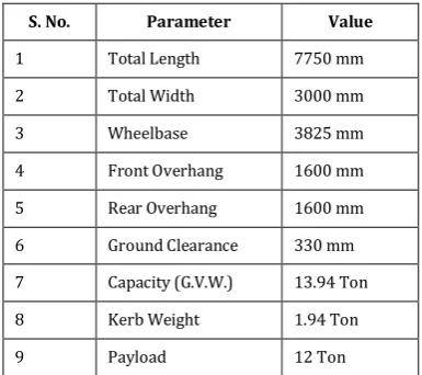
TABLE I. Specifications of Trailer Structure
S. No. Parameter Value
1 Total Length 7750 mm
2 Total Width 3000 mm
3 Wheelbase 3825 mm
4 Front Overhang 1600 mm
5 Rear Overhang 1600 mm
6 Ground Clearance 330 mm
7 Capacity (G.V.W.) 13.94 Ton
8 Kerb Weight 1.94 Ton
9 Payload 12 Ton
Trailer frame has been considered to be made from 'C'-channels of dimensions (ISMC 350 and ISMC 300) as per ISI standards.
1) Basic Calculations for Trailer Structure:
Capacity of Trailer = 13.94 Ton (Kerb Weight + Payload) Capacity of Trailer = 136.704 kN
Factor of Safety = 1.5
Total Load Capacity on the Trailer = 205.02 kN
The design of chassis structure has been performed by the consideration of concentrated loads as per the detailed of
centre of gravity. The chassis structure has two beams. So,
half load of the total load will act on one beam load acting on the trailer.
Load acting on one beam = 205.02
2 = 102.51 kN/Beam
2) Load Conditions for Trailer Structure:
Fig. 1. Total load acting on the beam
3) Fixed End Moments:
Moment Distribution Method: In Span AE,
MAE = (22.07 x 0.925) = 20.41 kN m
MEA = 0
In Span AB,
MAB = 𝑊1𝑎1𝑏1
2
𝐿2 + 𝑊2𝑎2𝑏22
𝐿2
= 32.37 × 2.1 × (1)2 (3.1)2 +
22.07 × 2.275 ×(0.8251)2 (3.1)2 MAB = 10.63 kN m
MBA = 𝑊1𝑏1𝑎1
2
𝐿2 + 𝑊2𝑏2𝑎22
𝐿2
= 32.37 × 1 × (2.1)(3.1)2 2+
22.07 × 0.8251 ×(2.275)2 (3.1)2
MBA = 24.65 kN m
In Span BC,
MBC = − 𝑊𝐿
8 =
− 3.924 ×1.45
8 = – 0.711 kN m
MCB = 𝑊𝐿
8 =
3.924 ×1.45
8 = 0.711 kN m In Span CJ (Cantilever)
MCJ = 22.072 x 0.925 = 20.414 kN m
MJC = 0
Stiffness Factor and Distribution Factor For Joint B,
kBA = 3 𝐸𝐼
𝐿𝐵𝐴 = 3 𝐸𝐼
3.1 = 0.967
kBC = 3 𝐸𝐼
𝐿𝐵𝐶 = 3 𝐸𝐼
1.45 = 2.069
D.F.(BA) = 𝑘𝐵𝐴
𝑘𝐵𝐴+ 𝑘𝐵𝐶 = 0.967
3.036 = 0.319
D.F.(BC) = 𝑘𝐵𝐶
𝑘𝐵𝐴+ 𝑘𝐵𝐶 = 2.069
3.036 = 0.681 D.F.(CB) and D.F.(AB) = 1 (Cantilever)
TABLE II. Moment Distribution Table
Joint Member
E A B C J
EA AE AB BA BC CB CJ JC
D.F. 0 1 0.319 0.681 1 0
F.E.M.
0 +20.41 – 10.6 3
+24.65 –0.711 +0.711 –20.414 0
–
9.78 19.703 0
4.89 9.85
+20.41 – 20.4 1
+19.76 +9.141 +20.41 –20.41
–9.225 –19.68
+20.41 – 20.4 1
+10.535 –10.535 +20.41 –20.41
4) Calculations for Free Bending Moment:
Span BC 𝑊𝑎𝑏
𝐿 =
3.924x0.800x0.650
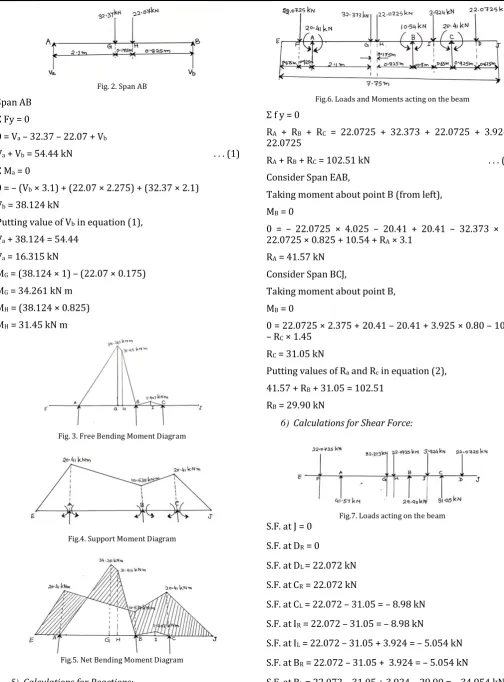
9 | P a g e Fig. 2. Span AB
Span AB Ʃ Fy = 0
0 = Va – 32.37 – 22.07 + Vb
Va + Vb = 54.44 kN . . . (1)
Ʃ Ma = 0
0 = – (Vb × 3.1) + (22.07 × 2.275) + (32.37 × 2.1)
Vb = 38.124 kN
Putting value of Vb in equation (1),
Va + 38.124 = 54.44
Va = 16.315 kN
MG = (38.124 × 1) – (22.07 × 0.175)
MG = 34.261 kN m
MH = (38.124 × 0.825)
MH = 31.45 kN m
Fig. 3. Free Bending Moment Diagram
Fig.4. Support Moment Diagram
Fig.5. Net Bending Moment Diagram
5) Calculations for Reactions:
Fig.6. Loads and Moments acting on the beam Ʃ f y = 0
RA + RB + RC = 22.0725 + 32.373 + 22.0725 + 3.924 +
22.0725
RA + RB + RC = 102.51 kN . . . (2)
Consider Span EAB,
Taking moment about point B (from left), MB = 0
0 = – 22.0725 × 4.025 – 20.41 + 20.41 – 32.373 × 1 – 22.0725 × 0.825 + 10.54 + RA × 3.1
RA = 41.57 kN
Consider Span BCJ,
Taking moment about point B, MB = 0
0 = 22.0725 × 2.375 + 20.41 – 20.41 + 3.925 × 0.80 – 10.54 – RC × 1.45
RC = 31.05 kN
Putting values of Ra and Rc in equation (2),
41.57 + RB + 31.05 = 102.51
RB = 29.90 kN
6) Calculations for Shear Force:
Fig.7. Loads acting on the beam S.F. at J = 0
S.F. at DR = 0
S.F. at DL = 22.072 kN
S.F. at CR = 22.072 kN
S.F. at CL = 22.072 – 31.05 = – 8.98 kN
S.F. at IR = 22.072 – 31.05 = – 8.98 kN
S.F. at IL = 22.072 – 31.05 + 3.924 = – 5.054 kN
S.F. at BR = 22.072 – 31.05 + 3.924 = – 5.054 kN
S.F. at BL = 22.072 – 31.05 + 3.924 – 29.90 = – 34.954 kN
10 | P a g e S.F. at HL = 22.072 – 31.05 + 3.924 – 29.90 + 22.072
= – 12.882 kN
S.F. at GR = 22.072 – 31.05 + 3.924 – 29.90 + 22.072
= – 12.882 kN
S.F. at GL = 22.072 – 31.05 + 3.924 – 29.90 + 22.072 +
32.373 = 19.491 kN
S.F. at AR = 22.072 – 31.05 + 3.924 – 29.90 + 22.072 +
32.373 = 19.491 kN
S.F. at AL = 22.072 – 31.05 + 3.824 – 29.90 + 22.072 +
32.373 – 41.57 = – 22.072 kN
S.F. at FR = 22.072 – 31.05 + 3.924 – 29.90 + 22.072 +
32.373 – 41.57 = – 22.072 kN
S.F. at FL = 22.071 – 31.05 + 3.924 – 29.90 + 22.072 +
32.373 – 41.57 + 22.072 = 0 kN S.F. at E = 0 kN
Fig.8. Shear Force Diagram
7) Calculations for Maximum Deflection:
Fig.9. Reactions acting on the beam
We consider a section X-X in DJ span at a distance x metre from E,
Taking moment of all forces about X–X section,
MXX = – 22.0725 [x – 0.675] + RA [x – 1.6] – 32.373 [x – 3.7]
– 22.0725 [x – 3.875] + RB [x – 4.7] – 3.924 [x – 5.5]
+ RC [x – 6.15] – 22.0725 [x – 7.075]
According to Macaulay’s theorem,
Mxx = EI d2y/dx2 = – 22.0725 [x – 0.675] + RA [x – 1.6] –
32.373 [x – 3.7] – 22.0725 [x –3.875] + RB [x – 4.7] – 3.924 [x – 5.5] + RC [x
– 6.15] – 22.0725 [x – 7.075] Integrating with respect to x, we get
EI dy/dx = – 22.0725 [x – 0.675]2/2 + RA [x – 1.6]2/2 –
32.373 [x – 3.7]2/2 – 22.0725 [x –3.875]2/2 +
RB [x–4.7]2/2 – 3.924 [x – 5.5]2/2 + RC [x –
6.15]2/2 – 22.0725 [x – 7.075]2/2 + C1
Again integrating with respect to x, we get
EI y = – 22.0725 [x – 0.675]3/6 + 41.57 [x – 1.6]3/6 –
32.373 [x – 3.7]3/6 – 22.0725 [x –3.875]3/6 +
29.90 [x – 4.7]3/6 – 3.924 [x – 5.5]3/6 + 31.05 [x –
6.15]3/6 – 22.0725 [x –7.075]3/6 + C1x + C2
. . . (3)
Applying boundary conditions, At A, i.e. at x = 1.6 m, y = 0
0 = – 22.0725 (1.6 – 0.675)3/6 + 1.6 C1 + C2
1.6 C1+ C2 = 2.9116 . . . (4)
At C, i.e. at x = 6.15 m, y = 0
0 = – 22.0725 (6.15 – 0.675)3/6 + 41.57 (6.15 – 1.6)3/6 –
32.373 (6.15 – 3.7)3/6 – 22.0725 (6.15 – 3.875)3/6 +
29.9 (6.15 – 4.7)3/6 – 3.924 (6.15 – 5.5)3/6 + 6.15 C1+
C2
6.15 C1 + C2 = 58.7697 . . . (5)
From equations (4) and (5), we get, C1 = 12.2765
C2= – 16.7308
Putting values of C1 and C2 in equation (3), we get
y = [– 22.0725 [x – 0.675]3/6 + 41.57 [x – 1.6]3/6 – 32.373
[x – 3.7]3/6 – 22.0725 [x – 3.875]3/6 + 299 [x – 4.7]3/6
– 3.924 [x – 5.5]3/6 + 31.05 [x – 6.15]3/6 – 22.0725 [x
– 7.075]3/6 + 12.2765 x – 16.7308] / EI
. . . (6)
Above equation is the general equation of Deflection. Deflection at E, i.e. at x = 0,
yE = – 16.7308 kN m3/(EI) = – 16.7308 × 10⁹ kN mm3/(EI)
Deflection at F, i.e. at x = 0.675 m
yF = (12.2765 × 0.675 – 16.7308)/(EI) = – 8.444 kN m3/(EI)
= – 8.4444 × 10⁹ kN mm3/(EI)
Deflection at G, i.e. at x = 3.7 m
yG = – 8.975 kN m3/(EI) = – 8.975109 kN mm3/(EI)
Deflection at H, i.e. at x = 3.875 m
yH = – 8.156 kN m3/(EI) = – 8.156 × 10⁹ kN mm3/(EI)
Deflection at I, i.e. at x = 5.5 m
yI = 3.8407 kN m3/(EI) = 3.8407×10⁹ kN mm3/(EI)
Deflection at D, i.e. at x = 7.075 m
yD = – 16.8493 kN m3/(EI) = – 16.8493 × 10⁹ kN mm3/(EI)
Deflection at J, i.e. x = 7.750 m
yJ = – 31.2728 kN m3/(EI) = – 31.2728 ×10⁹ kN mm/(EI)
Maximum Deflection occurs at J, yMax = yJ = – 31.2728 ×10⁹ kN mm/(EI)
11 | P a g e Fig.10. 'C'-Channels[14]
h = 350 mm, b = 100 mm,
thickness of flange (tf) = 13.5 mm, thickness of web (tw) =
8.1 mm
IXX = 10008.0 cm4 = 100080000 mm4
ZXX (Section Modulus) = 571.9 cm3 = 571900 mm3
According to general bending equation, 𝑀
𝐼 = 𝜎 𝑦=
𝐸 𝑅
Maximum bending moment acting on the beam, MMax = 34.261×10⁶ N mm
ZXX = 571.9 cm3 = 571900 mm3
Stress induced in the beam,
σ = MMax /ZXX = 34.261×10⁶ / 571900 = 59.9073 N/mm2
Maximum deflection produced on the beam, E = 205 GPa = 205 kN/mm2
IXX = 10008.0 cm4 =100080000 mm4
yMax = – (31.2728 × 10⁹) / (205 × 100080000) = 1.524 mm
downward
According to IS 800:2007[16],
Maximum Allowable Deflection = Span/300 mm = 7750/300 mm = 25.8333 mm
Since, 1.524 mm < 25.833 mm Hence, Design is safe.
The proposed trailer structure has two longitudinal members ('C' Channels of ISMC 350) and seven cross members ('C' Channels of ISMC 300).[14]
Fig.11. Proposed Trailer Structure
VI. SELECTION OF ADVANCED LIGHTWEIGHT MATERIAL FOR TRAILER STRUCTURE
The metal matrix composite of Aluminum-Beryllium, i.e. AlBeMet AM162 Extruded Bar has high modulus of elasticity with low-density and has 62 wt% commercially pure beryllium and 38 wt% commercially pure aluminum.
A. Properties of AlBeMet AM 162 Extruded Bar
Modulus of Elasticity = 202 GPa
Poisson's Ratio = 0.17
Density = 2071 kg/m3
Coeff. of Thermal Expansion = 13.91×10⁻⁶/oK Critical Damping Ratio = 1.5×10⁻³
Ultimate Tensile Strength = 400 MPa
Yield Strength = 276 MPa
VII. THEORETICAL DESIGN OF ADVANCED LIGHTWEIGHT MATERIAL TRAILER STRUCTURE
Maximum deflection produced on the beam with Advanced Lightweight Material, AlBeMet AM 162 Extruded Bar, E = 202 GPa = 202 kN/mm2
IXX = 100080000 mm4
yMax= – 31.2728 × 10
9
EI = –
31.2728 × 10⁹
202 × 100080000 = 1.547 mm Downward
According to IS 800:2007 [16], Maximum allowable deflection = 𝑆𝑝𝑎𝑛
300 = 7750
300 mm ∴ Maximum allowable deflection in beam = 25.833 mm Since, 1.547 mm is less than the maximum allowable deflection 25.833 mm.
Hence, Design is safe.
VIII. RESULTS
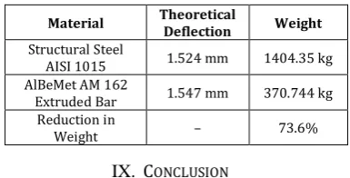
The results have been compared and shown in Table III below:
TABLE III. Results
Material Theoretical Deflection Weight
Structural Steel
AISI 1015 1.524 mm 1404.35 kg AlBeMet AM 162
Extruded Bar 1.547 mm 370.744 kg Reduction in
Weight – 73.6%
IX. CONCLUSION
The trailer structure has been designed for 12 ton payload for maintaining the strength using advanced lightweight material.
From the results, it has been found that the chassis structure with advanced lightweight material, i.e. AlBeMet AM 162 Extruded Bar has sufficient strength and withstands all the loads with a theoretical deflection of 1.547 mm which is less than that of maximum allowable deflection as per the standard, IS 800:2007.
12 | P a g e results to the protection of the environment from pollution.
X. FUTURE SCOPE
The finite element analysis of the trailer structure can be performed further for the validation and determination of displacements, stresses, strains and forces in structure and its components caused by the loads.
REFERENCES
[1] J. Galos, Dr M. Sutcliffe and Prof D. Cebon, “Design of a Lightweight Heavy Goods Vehicle Trailer”, European Transport Conference, Association for European Transport, pp. 1–17, 2014.
[2] D. Sharma and Y. D. Vora, “Design and Analysis of Heavy Duty Vehicle (Trailer) Chassis through FEM Software”, International Journal of Engineering Technology, Management and Applied Sciences, Vol. 5, Issue 4, pp. 574-580, April 2017.
[3] D. Sharma and Y. D. Vora, “Design and Vibration Analysis of Heavy Duty Vehicle (Trailer) Chassis Through FEM Software”, International Journal of Engineering Science Invention Research & Development, Vol. 3, Issue 11, pp. 707-712, May 2017.
[4] G. S. Datar, R. S. Bindu and D. V. Dandekar, “Design and Analysis of 40 Tonne Trailer Used in Heavy Commercial Vehicles”, International Journal on Theoretical and Applied Research in Mechanical Engineering (IJTARME), Vol.1, Issue 2, pp. 14-21, 2012.
[5] A. O. Moaaz and N. M. Ghazaly, “A Review of the Fatigue Analysis of Heavy Duty Truck Frames”, American Journal of Engineering Research (AJER), Vol. 3, Issue 10, pp 01-06, 2014.
[6] H. B. Patil, S. D. Kachave and E. R. Deore, “Stress Analysis of Automotive Chassis with Various Thicknesses”, IOSR Journal of Mechanical and Civil Engineering (IOSR-JMCE), Vol. 6, Issue 1, pp. 44-49, March - April 2013.
[7] A. Gosavi, A. K. Shrivastava and A. K. Sinha, “Structural Analysis of Six Axle Trailer Frame Design and Modification for Weight Reduction”, International Journal of Emerging Technology and Advanced Engineering, Volume 4, Issue 1, pp 523-531, January 2014. [8] O. Kurdi, R. A. Rahman, M. N. Tamin, “Stress Analysis of Heavy Duty
Truck Chassis using Finite Element Method”, ResearchGate, pp 1-7, 2015.
[9] A. S. Patel and J. Chitransh, “Design and Analysis of Tata 2518TC Truck Chassis Frame with Various Cross Sections using CAE Tools”,
International Journal of Engineering Sciences & Research Technology (IJESRT), Vol. 5, No. 9, pp. 692-714, 2016.
[10] J. Reimpell, H. Stoll, W. Jürgen, The Automotive Chassis: Engineering Principles, Great Britain, Butterworth Heinemann, Second Edition, , 2001.
[11] S. Ramamrutham and R. Narayanan, Strength of Materials, New Delhi, Danpat Rai Publishing Company, Nineteenth Edition, 2017. [12] G. H. Ryder, Strength of Materials, Macmillan Publishers India Ltd.,
Third Edition, 2011.
[13] J. Pawlowski and Guy Tidbury, Vehicle Body Engineering, London, Business Books Ltd., 1969.
[14] BIS, Handbook for Structural Engineers - Structural Steel Sections, SP:6 (1), 1964.
[15] Code of Practice for Construction and Approval of Truck Cabs & Truck Bodies, (Revision 1)/F, AIS-093, 2014.