Manufacturing and Materials Processing
Article
E
ff
ect of Graphene on Machinability of Glass Fiber
Reinforced Polymer (GFRP)
Khalid El-Ghaoui1, Jean-Francois Chatelain1,* and Claudiane Ouellet-Plamondon2
1 Mechanical Engineering Department,École de Technologie Supérieure, 1100 Notre-Dame West, Montreal, QC H3C 1K3, Canada
2 Construction Engineering Department,École de Technologie Supérieure, 1100 Notre-Dame West, Montreal, QC H3C 1K3, Canada
* Correspondence: [email protected]
Received: 25 June 2019; Accepted: 29 August 2019; Published: 3 September 2019
Abstract:Glass fiber reinforced polymers (GFRPs) are used extensively in many industries because of their low cost and high mechanical properties. Even if composite manufacturing processes are well controlled and allow to fabricate near net shapes, machining operations are still necessary to complete the manufacturing. As a composite material, GFRP machining remains difficult because of its heterogeneous and anisotropic character. This work intends to investigate the effect of graphene addition to the epoxy matrix of GFRP on its machinability. The epoxy was filled with 1 wt% graphene by mixing, sonicating, and then being used to produce unidirectional GFRP laminate by hand layup methods. Thermocouples were bonded on a chemical vapor deposition (CVD) diamond coated tool in order to record cutting temperatures during the trimming process. The cutting forces were recorded and the resulting surface roughness after trimming was measured to qualify properly the machinability of the modified GFRP. Compared to the reference material (GFRP without graphene), the additive improved the machining process by decreasing the cutting temperature and forces as well as the surface roughness without deteriorating the inter-laminar shear strength.
Keywords: GFRP; composite; machining; graphene; cutting temperature
1. Introduction
Thanks to their low density, fiber reinforced polymers (FRPs) are widely used in many manufacturing applications. Glass fiber reinforced polymers (GFRPs) represent more than 90% of the FRP industry. Its low cost and its good chemical stability are appreciated, especially in the automotive and marine industrial sectors [1]. Even though GFRP parts are generally made to near net shapes, machining operations such as drilling and milling, are nevertheless required to respect dimensional and geometric tolerances. Machining of composite materials is still not well mastered and is different from machining metallic materials. The heterogeneous and anisotropic nature brought by the fiber causes many difficulties and issues during the machining processes. The cutting mechanisms are hardly understandable and depend highly on the fiber orientation [2].
Mechanical damages, such as uncut fibers, fiber pull-out, matrix cracking, and delamination may be found depending on the fiber orientation, the cutting tool type, and the machining parameters [3–5]. These damages lead to poor surface integrity of the machined surface, craters generated by fiber pull-out cause an excessive roughness and precocious mechanical failure may happen because of the cracking of matrix materials [4]. The apparition of deteriorations can be explained through the analysis of the chip removal mechanism, which occurs for fiber orientation between 0◦and−90◦with respect to the cutting direction. As illustrated in Figure1, these orientations do not allow a strong maintaining of the fibers, which tend to bend under the cutting forces during machining. Compression into the fiber
J. Manuf. Mater. Process.2019,3, 78 2 of 12
axis is also created by the tool and makes the fiber breakage difficult to happen. Fiber/matrix break-up occurs at the tool cutting edge. Until chip separation, break-up propagates beneath the machined surface [5,6].
J. Manuf. Mater. Process. 2019, 3, x FOR PEER REVIEW 2 of 12
happen. Fiber/matrix break-up occurs at the tool cutting edge. Until chip separation, break-up propagates beneath the machined surface [5,6].
Figure 1. Cutting mechanism of fiber reinforced polymer (FRP) with an −45° fiber orientation.
In recent years, thermal behavior of FRP machining has retained the attention of researchers. Thermal damages are observed on the machined surface when temperature rises high enough to exceed the matrix glass transition temperature. Poor quality of the machined surface is therefore induced, matrix is inconsistently spread, and fibers are messy [7,8]. Machining at high temperature also promotes premature failure and significant decrease in mechanical properties [9,10]. Unlike metals, FRP chip separation occurs by brittle fracture which generates negligible thermal energy, and because of the chips powder nature, friction at the tool rake face is also considered as negligible. The temperature rise is then mainly explained by the friction, which takes place at the tool/workpiece interface [11,12]. Usually in dry machining of metallic materials, the heat produced by the cutting process is evacuated through the chips, the workpiece, and the cutting tool. However, in FRP machining, the heat is mainly evacuated by the tool and lesser by the chips since these materials have poor thermal conductivity [13].
Friction on the workpiece leads to a rapid growth of tool wear in addition to causing high temperatures during the process. Wear is a serious problem in FRP machining since it conducts to more mechanical and thermal damages. The cutting process becomes less efficient and fiber cut is no longer clean because of the tool bluntness [14]. Considering the high abrasiveness character of fiber, wear is widely predominant on the tool clearance face where the friction takes place with the workpiece. No wear occurs on the tool rake face, since the powder nature of chips does not create friction at the tool/chip interface [15]. Tools such as polycrystalline diamonds (PCD) or diamond coated carbides are commonly used for FRP machining since they show better resistance to wear [2]. Optimizing the cutting conditions can also significantly minimize the tool wear growing [7,16]. Despite all the improvements made, FRP machining still remains expensive because of the cost and the short lifetime of the cutting tools.
Synthetized for the first time in 2004, graphene actually defines a unique layer of the hexagonal arrangement of graphite [17]. Thanks to its particular 2D structure, graphene shows a high specific surface area, and astonishing properties. It is currently the most conductive and resistant material known [18,19]. Graphene applications are very promising, since new low-cost manufacturing methods were developed [20]. One of the most promising applications is its use as filler into polymers. Graphene based nanocomposites have shown significant improvement on electrical and thermal conductivity as well as mechanical properties [21–23].
Tool
Matrix
cracking
Fiber/matrix
break-up
propagation
Poor maintaining
of the fiber by
the workpiece
-45°
Cutting direction
Figure 1.Cutting mechanism of fiber reinforced polymer (FRP) with an−45◦fiber orientation.
In recent years, thermal behavior of FRP machining has retained the attention of researchers. Thermal damages are observed on the machined surface when temperature rises high enough to exceed the matrix glass transition temperature. Poor quality of the machined surface is therefore induced, matrix is inconsistently spread, and fibers are messy [7,8]. Machining at high temperature also promotes premature failure and significant decrease in mechanical properties [9,10]. Unlike metals, FRP chip separation occurs by brittle fracture which generates negligible thermal energy, and because of the chips powder nature, friction at the tool rake face is also considered as negligible. The temperature rise is then mainly explained by the friction, which takes place at the tool/workpiece interface [11,12]. Usually in dry machining of metallic materials, the heat produced by the cutting process is evacuated through the chips, the workpiece, and the cutting tool. However, in FRP machining, the heat is mainly evacuated by the tool and lesser by the chips since these materials have poor thermal conductivity [13]. Friction on the workpiece leads to a rapid growth of tool wear in addition to causing high temperatures during the process. Wear is a serious problem in FRP machining since it conducts to more mechanical and thermal damages. The cutting process becomes less efficient and fiber cut is no longer clean because of the tool bluntness [14]. Considering the high abrasiveness character of fiber, wear is widely predominant on the tool clearance face where the friction takes place with the workpiece. No wear occurs on the tool rake face, since the powder nature of chips does not create friction at the tool/chip interface [15]. Tools such as polycrystalline diamonds (PCD) or diamond coated carbides are commonly used for FRP machining since they show better resistance to wear [2]. Optimizing the cutting conditions can also significantly minimize the tool wear growing [7,16]. Despite all the improvements made, FRP machining still remains expensive because of the cost and the short lifetime of the cutting tools.
Over the last decade, many studies have been carried out on FRP machining. Different ways to enhance machinability have been investigated, such as cutting conditions, fiber orientation, tools material, and tools geometry. However, barely no studies have considered improving machining behavior by adding fillers into the matrix. This study innovates in investigating the effects of a graphene filled matrix on the machinability of GFRP. Thanks to its high thermal conductivity, graphene is expected to lower cutting temperatures, and hence reduce thermal damage occurrence and extend tool lives.
2. Materials and Methods
2.1. Materials Preparation
Material preparation begins with the filling of the epoxy resin (Marine 820 from Axson Technologies, Madison Heights, MI, USA) with graphene. Graphene concentration was fixed at 1 wt%, higher percentages have been found to deteriorate mechanical properties since the particles tend to agglomerate [24–26] and may also cause an increase of the resin viscosity, making the resin incompatible with the GFRP fabrication process. A commercially available graphene was used for this study (GrapheneBlack 0X) and supplied by NanoXplore Inc. (Montreal, QC, Canada). Graphene was first mixed directly into the resin for 30 min at 3500 rpm using a Silverson L5M-A high-shear mechanical stirrer to disperse homogeneously the particles into the matrix. Then, the graphene filled resin was sonicated with a Qsonica Q700 sonicator for one hour at a frequency of 20 kHz. Sonication is an important stage in resin filling processes, especially when platelets-like nanoparticles are added. This method helps the particles exfoliation, which is important to obtain a high interaction with the polymer. To limit the temperature rising due to the mechanical mixing and sonication, the solution was placed in an iced water bath during the preparation. The resin was then degassed for one hour to extract air bubbles generated by the previous mixing methods. Finally, the hardener was added and manually mixed with the resin respecting the proportions of 100:18 given by the supplier.
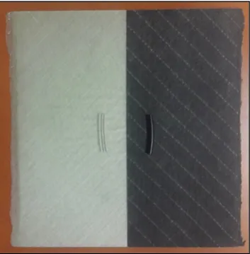
To avoid the graphene filtration by fibers and ensure a homogeneous dispersion into the composite, GFRP was prepared by the hand layup method. Unidirectional glass fiber fabrics (TG-13-U from Texonic, Montreal, QC, Canada) were successively deposited and impregnated in the resin until the desired thickness was obtained. The laminate was vacuum bagged during the cure to remove excess resin and limit the human influence factor. A second laminate was made following the same process with net epoxy to allow comparison. Both laminates had a thickness of about 3.4 mm. The laminate became completely opaque and black because of the resin coloration by graphene. Comparison between both laminates and resins are illustrated in Figure2.
J. Manuf. Mater. Process. 2019, 3, x FOR PEER REVIEW 3 of 12
Over the last decade, many studies have been carried out on FRP machining. Different ways to enhance machinability have been investigated, such as cutting conditions, fiber orientation, tools material, and tools geometry. However, barely no studies have considered improving machining behavior by adding fillers into the matrix. This study innovates in investigating the effects of a graphene filled matrix on the machinability of GFRP. Thanks to its high thermal conductivity, graphene is expected to lower cutting temperatures, and hence reduce thermal damage occurrence and extend tool lives.
2. Materials and Methods
2.1. Materials Preparation
Material preparation begins with the filling of the epoxy resin (Marine 820 from Axson Technologies, Madison Heights, MI, USA) with graphene. Graphene concentration was fixed at 1 wt%, higher percentages have been found to deteriorate mechanical properties since the particles tend to agglomerate [24–26] and may also cause an increase of the resin viscosity, making the resin incompatible with the GFRP fabrication process. A commercially available graphene was used for this study (GrapheneBlack 0X) and supplied by NanoXplore Inc. (Montreal, QC, Canada). Graphene was first mixed directly into the resin for 30 min at 3500 rpm using a Silverson L5M-A high-shear mechanical stirrer to disperse homogeneously the particles into the matrix. Then, the graphene filled resin was sonicated with a Qsonica Q700 sonicator for one hour at a frequency of 20 kHz. Sonication is an important stage in resin filling processes, especially when platelets-like nanoparticles are added. This method helps the particles exfoliation, which is important to obtain a high interaction with the polymer. To limit the temperature rising due to the mechanical mixing and sonication, the solution was placed in an iced water bath during the preparation. The resin was then degassed for one hour to extract air bubbles generated by the previous mixing methods. Finally, the hardener was added and manually mixed with the resin respecting the proportions of 100:18 given by the supplier.
To avoid the graphene filtration by fibers and ensure a homogeneous dispersion into the composite, GFRP was prepared by the hand layup method. Unidirectional glass fiber fabrics (TG-13-U from Texonic, Montreal, QC, Canada) were successively deposited and impregnated in the resin until the desired thickness was obtained. The laminate was vacuum bagged during the cure to remove excess resin and limit the human influence factor. A second laminate was made following the same process with net epoxy to allow comparison. Both laminates had a thickness of about 3.4 mm. The laminate became completely opaque and black because of the resin coloration by graphene. Comparison between both laminates and resins are illustrated in Figure 2.
Figure 2. Plaques with net epoxy (left) and 1 wt% graphene addition to epoxy (right) and their respective epoxy.
J. Manuf. Mater. Process.2019,3, 78 4 of 12
2.2. Machining Tests
Both laminates were machined using a Huron K2X10 three-axis CNC machine. As illustrated in Figure3, the plaques were fixed on a Kistler 9255 B dynamometer table in order to measure cutting forces. Milling was carried out in dry conditions with the fiber orientation of−45◦with respect to the cutting direction. This orientation was selected since it has been found the worst case in terms of roughness and material integrity of the laminate following the cutting process [4,14,27]. Since this study aims to investigate the effect of graphene, cutting conditions were kept constant. The feed rate was set at 0.114 mm/rev while the cutting speed was set at 300 m/min, for which previous studies demonstrated higher cutting tool life and best quality of cut [7,28]. The machining process was trimming (full engaged tool) along the laminates over a 300 mm length. Two machining sequences were performed on each laminate. The running order of the machining sequences was taken to alternate both laminates (Figure4). Thereby ensuring that tool wear, which may occur during the first test, is not responsible for the temperature and force increase observed in the second one. Taking a new tool for each test was not viable since variations on the thermal response could bias the temperature comparisons.
J. Manuf. Mater. Process.2019, 3, x FOR PEER REVIEW 4 of 12
2.2. Machining Tests
Both laminates were machined using a Huron K2X10 three-axis CNC machine. As illustrated in Figure 3, the plaques were fixed on a Kistler 9255 B dynamometer table in order to measure cutting forces. Milling was carried out in dry conditions with the fiber orientation of −45° with respect to the cutting direction. This orientation was selected since it has been found the worst case in terms of roughness and material integrity of the laminate following the cutting process [4,14,27]. Since this study aims to investigate the effect of graphene, cutting conditions were kept constant. The feed rate was set at 0.114 mm/rev while the cutting speed was set at 300 m/min, for which previous studies demonstrated higher cutting tool life and best quality of cut [7,28]. The machining process was trimming (full engaged tool) along the laminates over a 300 mm length. Two machining sequences were performed on each laminate. The running order of the machining sequences was taken to alternate both laminates (Figure 4). Thereby ensuring that tool wear, which may occur during the first test, is not responsible for the temperature and force increase observed in the second one. Taking a new tool for each test was not viable since variations on the thermal response could bias the temperature comparisons.
Figure 3. Glass fiber reinforced polymer (GFRP) machining setup.
Figure 4. Running order of the machining sequences.
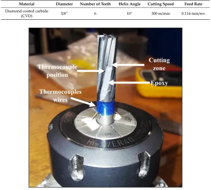
Machining tests were performed with chemical vapor deposition (CVD) diamond coated tools equipped with thermocouples to measure the cutting temperatures. The specifications of the cutting tool are indicated in Table 1. Two thermocouples (Type-K from Omega, Biel/Bienne, Switzerland) were positioned at the same height on two diametrically opposed teeth of the tool (Figure 5). Given that the machining test duration is only about 15 s, precautions were taken to optimize thermal response and hence allow a more accurate and rapid measurement. Thermocouple wire diameter of
GFRP w/
graphene
1st sequence
GFRP w/ net
epoxy
2nd sequence
GFRP w/
graphene
3rd sequence
GFRP w/ net
epoxy
4th sequence
GFRP
Machining
fixture
Dynamometer
table
Figure 3.Glass fiber reinforced polymer (GFRP) machining setup.
J. Manuf. Mater. Process.2019, 3, x FOR PEER REVIEW 4 of 12
2.2. Machining Tests
Both laminates were machined using a Huron K2X10 three-axis CNC machine. As illustrated in Figure 3, the plaques were fixed on a Kistler 9255 B dynamometer table in order to measure cutting forces. Milling was carried out in dry conditions with the fiber orientation of −45° with respect to the cutting direction. This orientation was selected since it has been found the worst case in terms of roughness and material integrity of the laminate following the cutting process [4,14,27]. Since this study aims to investigate the effect of graphene, cutting conditions were kept constant. The feed rate was set at 0.114 mm/rev while the cutting speed was set at 300 m/min, for which previous studies demonstrated higher cutting tool life and best quality of cut [7,28]. The machining process was trimming (full engaged tool) along the laminates over a 300 mm length. Two machining sequences were performed on each laminate. The running order of the machining sequences was taken to alternate both laminates (Figure 4). Thereby ensuring that tool wear, which may occur during the first test, is not responsible for the temperature and force increase observed in the second one. Taking a new tool for each test was not viable since variations on the thermal response could bias the temperature comparisons.
Figure 3. Glass fiber reinforced polymer (GFRP) machining setup.
Figure 4. Running order of the machining sequences.
Machining tests were performed with chemical vapor deposition (CVD) diamond coated tools equipped with thermocouples to measure the cutting temperatures. The specifications of the cutting tool are indicated in Table 1. Two thermocouples (Type-K from Omega, Biel/Bienne, Switzerland) were positioned at the same height on two diametrically opposed teeth of the tool (Figure 5). Given that the machining test duration is only about 15 s, precautions were taken to optimize thermal response and hence allow a more accurate and rapid measurement. Thermocouple wire diameter of
GFRP w/
graphene
1st sequence
GFRP w/ net
epoxy
2nd sequence
GFRP w/
graphene
3rd sequence
GFRP w/ net
epoxy
4th sequence
GFRP
Machining
fixture
Dynamometer
table
Figure 4.Running order of the machining sequences.
hence allow a more accurate and rapid measurement. Thermocouple wire diameter of 0.08 mm was used, since it is the smallest available. Thermal linkage between the tool and the thermocouple was assured by an Omegabond 400 cement, which presents a high thermal conductivity. To prevent them from debonding while machining, thermocouples and cement were entirely protected using an epoxy adhesive. A distance of 2.2 mm was set between the thermocouples and the upper laminate’s face. This distance was selected based on several tests in order to avoid thermocouples snatching. Finally, the thermocouples were connected to a temperature measurement system placed into the mandrel. This special mandrel (type M320, from MICHIGAN SCIENTIFIC Corporation, Charlevoix, MI, USA) allows the temperature signal transmission through a wireless system.
Table 1.Tool and cutting parameters.
Material Diameter Number of Teeth Helix Angle Cutting Speed Feed Rate
Diamond coated carbide
(CVD) 3/8” 6 10
◦
300 m/min 0.114 mm/rev
J. Manuf. Mater. Process.2019, 3, x FOR PEER REVIEW 5 of 12
0.08 mm was used, since it is the smallest available. Thermal linkage between the tool and the thermocouple was assured by an Omegabond 400 cement, which presents a high thermal conductivity. To prevent them from debonding while machining, thermocouples and cement were entirely protected using an epoxy adhesive. A distance of 2.2 mm was set between the thermocouples and the upper laminate’s face. This distance was selected based on several tests in order to avoid thermocouples snatching. Finally, the thermocouples were connected to a temperature measurement system placed into the mandrel. This special mandrel (type M320, from MICHIGAN SCIENTIFIC Corporation, Charlevoix, MI, USA) allows the temperature signal transmission through a wireless system.
Table 1. Tool and cutting parameters.
Material Diameter Number of
Teeth Helix Angle
Cutting
Speed Feed Rate
Diamond coated carbide
(CVD) 3/8” 6 10° 300 m/min 0.114 mm/rev
Figure 5. Equipped tool.
2.3. Roughness Measurement
Roughness measurement was performed using a Mitutoyo SJ-410 profilometer. Because the tool was fully engaged, two machined surfaces were produced during milling. Considering that down milling is not recommended in FRP machining [4,9], only the edges machined by up milling were considered for the roughness measurements. Roughness determination on machined FRP is known to be quite difficult because of low repeatability of the measurements. In order to avoid large uncertainties, roughness measurements were therefore taken at seven different positions on each machined surface. Profilometer settings were selected according to the ISO 4284-1997 standard and are specified in Table 2.
Thermocouple
position
Thermocouples
wires
Epoxy
Cutting
zone
Figure 5.Equipped tool.
2.3. Roughness Measurement
J. Manuf. Mater. Process.2019,3, 78 6 of 12
Table 2.Profilometer settings.
Parameter Ra
Sampling length 2.5 mm
Cut-off 2.5 mm
Number of measures 8
Evaluation length 20 mm Number of points 40,000
2.4. Short-Beam Tests
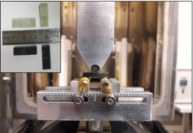
Fiber/matrix interaction is quite relevant in FRP machining since chips removal process starts at this interface [5,6]. In order to investigate this interaction, inter-laminar shear strength (ILSS) measurement through short-beam test was done. The experiment was performed according to the ASTM D2344 standard. Five rectangular specimens were cut on each laminate with a fiber orientation of 0◦using a diamond saw. The tests were carried out using an MTS Alliance RF/200 universal testing machine at a crosshead speed set at 1 mm/min (Figure6). ILSS was calculated from the maximal recorded forces.
J. Manuf. Mater. Process.2019, 3, x FOR PEER REVIEW 6 of 12
Table 2. Profilometer settings.
Parameter Ra Sampling length 2.5 mm
Cut-off 2.5 mm
Number of measures 8 Evaluation length 20 mm Number of points 40,000
2.4. Short-Beam Tests
Fiber/matrix interaction is quite relevant in FRP machining since chips removal process starts at this interface [5,6]. In order to investigate this interaction, inter-laminar shear strength (ILSS) measurement through short-beam test was done. The experiment was performed according to the ASTM D2344 standard. Five rectangular specimens were cut on each laminate with a fiber orientation of 0° using a diamond saw. The tests were carried out using an MTS Alliance RF/200 universal testing machine at a crosshead speed set at 1 mm/min (Figure 6). ILSS was calculated from the maximal recorded forces.
Figure 6. Short-beam tests and specimens.
3. Results and Discussion
3.1. Cutting Forces
The cutting forces were measured in each direction and transmitted by the Kistler dynamometer while machining. To by-pass, the high fluctuation of the raw signal, an average and sample signal was computed (Figure 7). Because of the transitional regime and vibrations happening when the tool goes into and comes out of the workpiece, data from the beginning and the end of the tests were not considered for the calculations. To allow a comparison between experiments, the recorded forces were averaged and are presented in Figure 8. Even if forces are relatively low, a decrease of 12.4% is noticed on the average feed forces, which drops from 76.3 N for the GFRP with net epoxy to 66.8 N with 1 wt% graphene. Decrease is less perceivable on normal forces. Reducing the cutting forces is desired since it promotes machinability by softening the cutting process. The cutting mechanism causes damages in FRP machining [5,6] but by reducing forces, chips are more easily removed and do not snatch from the workpiece fewer damages are hence caused on the surface. Slower tool wear growing can also be obtained because the tool is less solicited.
Figure 6.Short-beam tests and specimens.
3. Results and Discussion
3.1. Cutting Forces
the workpiece fewer damages are hence caused on the surface. Slower tool wear growing can also be obtained because the tool is less solicited.
J. Manuf. Mater. Process.2019, 3, x FOR PEER REVIEW 7 of 12
Figure 7. Forces signals.
Figure 8. Cutting forces.
3.2. Roughness
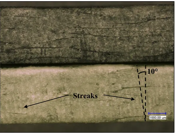
Roughness measurements can also indicate improvement on machinability. Figure 9 shows the average value of the arithmetic roughness (Ra) for both laminates. As illustrated, a decreased roughness is hence observed for the laminate filled with graphene with an average roughness of 7.3 µm against 8.5 µm for the reference GFRP. However, the error bars are relatively high and may be a source of confusion. A Student’s test was performed on the data. The test allowed accepting the hypothesis that the average roughness is lower in the modified GFRP with a p-value of 0.4%. Low roughness is difficult to obtain with FRP materials but is highly desired since it generally means a good quality of the machined surface. The current decrease can be explained by the reduced forces observed previously. Fewer damages are caused on the surface, because the chip separation that occurs is less brutal and occurs nearer the tool cutting edge. Damages caused by the cutting mechanism are hence less deep, decreasing the roughness. This is asserted in Figure 10, where streaks having an orientation of 10° (as the tool helix angle) caused by machining are clearly visible on the reference GFRP and lesser with the incorporation of graphene.
0 5 10 15 20 25 30
-200 0 200 Time (s) Feed for ce (N )
0 5 10 15 20 25 30
-200 0 200 Time (s) N or m al fo rce ( N ) Raw signal Averaged signal 0 10 20 30 40 50 60 70 80 90 0% 1% Force (N)
Graphene concentration (wt%)
Feed force Normal force Figure 7.Forces signals.
J. Manuf. Mater. Process.2019, 3, x FOR PEER REVIEW 7 of 12
Figure 7. Forces signals.
Figure 8. Cutting forces.
3.2. Roughness
Roughness measurements can also indicate improvement on machinability. Figure 9 shows the average value of the arithmetic roughness (Ra) for both laminates. As illustrated, a decreased roughness is hence observed for the laminate filled with graphene with an average roughness of 7.3 µm against 8.5 µm for the reference GFRP. However, the error bars are relatively high and may be a source of confusion. A Student’s test was performed on the data. The test allowed accepting the hypothesis that the average roughness is lower in the modified GFRP with a p-value of 0.4%. Low roughness is difficult to obtain with FRP materials but is highly desired since it generally means a good quality of the machined surface. The current decrease can be explained by the reduced forces observed previously. Fewer damages are caused on the surface, because the chip separation that occurs is less brutal and occurs nearer the tool cutting edge. Damages caused by the cutting mechanism are hence less deep, decreasing the roughness. This is asserted in Figure 10, where streaks having an orientation of 10° (as the tool helix angle) caused by machining are clearly visible on the reference GFRP and lesser with the incorporation of graphene.
0 5 10 15 20 25 30
-200 0 200 Time (s) Feed for ce (N )
0 5 10 15 20 25 30
-200 0 200 Time (s) N or m al fo rce ( N ) Raw signal Averaged signal 0 10 20 30 40 50 60 70 80 90 0% 1% Force (N)
Graphene concentration (wt%)
Feed force Normal force
Figure 8.Cutting forces.
3.2. Roughness
J. Manuf. Mater. Process.2019,3, 78 8 of 12
brutal and occurs nearer the tool cutting edge. Damages caused by the cutting mechanism are hence less deep, decreasing the roughness. This is asserted in Figure10, where streaks having an orientation of 10◦(as the tool helix angle) caused by machining are clearly visible on the reference GFRP and lesser with the incorporation of graphene.J. Manuf. Mater. Process.2019, 3, x FOR PEER REVIEW 8 of 12
Figure 9. Surface roughness measurements.
Figure 10. Micrograph of machined surface of GFRP with (top) and without (bottom) graphene.
3.3. Cutting Temperatures
Cutting temperatures were recorded using thermocouples and the wireless measurement system during spindle rotation. Figure 11 shows the evolution of the temperatures along the 300 mm cutting length. Two curves for each laminate are drawn, since the experiments were repeated for each GFRP material. Once the tool starts to cut, the temperature rises rapidly and seems to converge to a final value, despite a slight lag at the beginning due to the thermocouples thermal response. The length of cut was not long enough to converge and reach a constant value, temperatures then decreased when the tool came out of the laminate. Even with a 300 mm cutting length, conclusions can be drawn. Only 15 s of machining is enough to reach temperatures above 160 °C, which exceed the thermal resistance of most epoxies [1,29]. Hence, thermal damages may be inflicted to the matrix.
0 2 4 6 8 10 12
0% 1%
Ra
(µm)
Graphene concentration (wt%)
Streaks
10°
Figure 9.Surface roughness measurements.J. Manuf. Mater. Process.2019, 3, x FOR PEER REVIEW 8 of 12
Figure 9. Surface roughness measurements.
Figure 10. Micrograph of machined surface of GFRP with (top) and without (bottom) graphene.
3.3. Cutting Temperatures
Cutting temperatures were recorded using thermocouples and the wireless measurement system during spindle rotation. Figure 11 shows the evolution of the temperatures along the 300 mm cutting length. Two curves for each laminate are drawn, since the experiments were repeated for each GFRP material. Once the tool starts to cut, the temperature rises rapidly and seems to converge to a final value, despite a slight lag at the beginning due to the thermocouples thermal response. The length of cut was not long enough to converge and reach a constant value, temperatures then decreased when the tool came out of the laminate. Even with a 300 mm cutting length, conclusions can be drawn. Only 15 s of machining is enough to reach temperatures above 160 °C, which exceed the thermal resistance of most epoxies [1,29]. Hence, thermal damages may be inflicted to the matrix.
0 2 4 6 8 10 12
0% 1%
Ra
(µm)
Graphene concentration (wt%)
Streaks
10°
Figure 10.Micrograph of machined surface of GFRP with (top) and without (bottom) graphene.
3.3. Cutting Temperatures
15 s of machining is enough to reach temperatures above 160◦C, which exceed the thermal resistance of most epoxies [J. Manuf. Mater. Process. 1,29]. Hence, thermal damages may be inflicted to the matrix.2019, 3, x FOR PEER REVIEW 9 of 12
Figure 11. Cutting temperature curves.
Although all curves have the same trend, they quickly split from each other. For both cutting sequences, the GFRP filled with graphene show lower temperatures than the regular one. It can be asserted that the current temperature drop is only explained by the graphene presence and not by the tool wear occurring during the tests. If graphene had not an effect, the temperature curves would be alternated according to the running order of the machining sequences (Figure 4) since a growing tool wear lead to temperature increase, as observed in previous work [9]. Figure 12 shows the maximum temperatures (temperatures at 300 mm) for each laminate. A decrease of 14 °C is observed due to the graphene effects. Because edge trimming is one of the main GFRP machining operations, cutting distances are generally much longer than 300 mm in industry. As seen in Figure 11, the more the cutting length is long, the more the temperature difference between samples are high. So, the difference of 14 °C observed here will become much more important in a real manufacturing context. Thus, graphene may allow avoiding exceeding the glass transition temperature during GFRP machining.
Figure 12. Maximal cutting temperatures.
0 20 40 60 80 100 120 140 160 180 200
0 50 100 150 200 250 300 350
Temperature
(°C)
Cutting length (mm)
1 wt% graphene
Net epoxy
174.9
161.1
150 155 160 165 170 175 180
0% 1%
Maximal
temperature
(°C)
Graphene concentration (wt%) Figure 11.Cutting temperature curves.
Although all curves have the same trend, they quickly split from each other. For both cutting sequences, the GFRP filled with graphene show lower temperatures than the regular one. It can be asserted that the current temperature drop is only explained by the graphene presence and not by the tool wear occurring during the tests. If graphene had not an effect, the temperature curves would be alternated according to the running order of the machining sequences (Figure4) since a growing tool wear lead to temperature increase, as observed in previous work [9]. Figure12shows the maximum temperatures (temperatures at 300 mm) for each laminate. A decrease of 14◦C is observed due to the graphene effects. Because edge trimming is one of the main GFRP machining operations, cutting distances are generally much longer than 300 mm in industry. As seen in Figure11, the more the cutting length is long, the more the temperature difference between samples are high. So, the difference of 14◦C observed here will become much more important in a real manufacturing context. Thus, graphene may allow avoiding exceeding the glass transition temperature during GFRP machining.
J. Manuf. Mater. Process. 2019, 3, x FOR PEER REVIEW 9 of 12
Figure 11. Cutting temperature curves.
Although all curves have the same trend, they quickly split from each other. For both cutting sequences, the GFRP filled with graphene show lower temperatures than the regular one. It can be asserted that the current temperature drop is only explained by the graphene presence and not by the tool wear occurring during the tests. If graphene had not an effect, the temperature curves would be alternated according to the running order of the machining sequences (Figure 4) since a growing tool wear lead to temperature increase, as observed in previous work [9]. Figure 12 shows the maximum temperatures (temperatures at 300 mm) for each laminate. A decrease of 14 °C is observed due to the graphene effects. Because edge trimming is one of the main GFRP machining operations, cutting distances are generally much longer than 300 mm in industry. As seen in Figure 11, the more the cutting length is long, the more the temperature difference between samples are high. So, the difference of 14 °C observed here will become much more important in a real manufacturing context. Thus, graphene may allow avoiding exceeding the glass transition temperature during GFRP machining.
Figure 12. Maximal cutting temperatures.
0 20 40 60 80 100 120 140 160 180 200
0 50 100 150 200 250 300 350
Temperature
(°C)
Cutting length (mm)
1 wt% graphene
Net epoxy
174.9
161.1
150 155 160 165 170 175 180
0% 1%
Maximal
temperature
(°C)
Graphene concentration (wt%)
J. Manuf. Mater. Process.2019,3, 78 10 of 12
As described above, the poor thermal conductivity of FRP restricts the heat evacuation. In this case, the temperature decrease showed in Figure12may be explained by the enhancement of the GFRPs thermal conductivity. Other researches have shown the capacity of graphene to improve thermal conductivity of polymers [21,23]. Because the workpiece is more conductive, the tool accumulates less heat and remains cooler. The temperature drop may also be related to the cutting forces decrease observed in Figure8. As explained in the introduction, friction is the main source of heat in our case. Less heat is generated, because forces are lower and temperatures are therefore decreased. High temperatures are undesirable in FRP machining since they lead to serious issues, such as high occurrence of thermal damages and shorter tool life. A decrease in cutting temperature can lead to real improvement on the machining process. Further studies should be carried out to investigate deeper the mechanisms happening by graphene addition as well as the effects on tool life and surface integrity over longer cutting lengths.
3.4. Interlaminar Shear Strength
Previous results showed that graphene additive allowed for improving the machinability of GFRPs. It is important to make sure that such addition does not impair the mechanical properties of the material. ILSS is a good indicator of the fiber/matrix interaction. The fiber/matrix interaction is relevant for the mechanical properties of composites since it is a critical point for the stress transmission between both phases of the composite [30,31]. The average ILSS values of the five specimens are presented in Figure13, no variation is observed between the two materials. This result means that the fiber/matrix interaction is not altered by the presence of graphene.
J. Manuf. Mater. Process.2019, 3, x FOR PEER REVIEW 10 of 12
As described above, the poor thermal conductivity of FRP restricts the heat evacuation. In this case, the temperature decrease showed in Figure 12 may be explained by the enhancement of the GFRPs thermal conductivity. Other researches have shown the capacity of graphene to improve thermal conductivity of polymers [21,23]. Because the workpiece is more conductive, the tool accumulates less heat and remains cooler. The temperature drop may also be related to the cutting forces decrease observed in Figure 8. As explained in the introduction, friction is the main source of heat in our case. Less heat is generated, because forces are lower and temperatures are therefore decreased. High temperatures are undesirable in FRP machining since they lead to serious issues, such as high occurrence of thermal damages and shorter tool life. A decrease in cutting temperature can lead to real improvement on the machining process. Further studies should be carried out to investigate deeper the mechanisms happening by graphene addition as well as the effects on tool life and surface integrity over longer cutting lengths.
3.4. Interlaminar Shear Strength
Previous results showed that graphene additive allowed for improving the machinability of GFRPs. It is important to make sure that such addition does not impair the mechanical properties of the material. ILSS is a good indicator of the fiber/matrix interaction. The fiber/matrix interaction is relevant for the mechanical properties of composites since it is a critical point for the stress transmission between both phases of the composite [30,31]. The average ILSS values of the five specimens are presented in Figure 13, no variation is observed between the two materials. This result means that the fiber/matrix interaction is not altered by the presence of graphene.
Figure 13. Interlaminar shear strength (ILSS).
4. Conclusions
The present study aimed to investigate the effects of a graphene filled matrix on GFRP machinability. Unidirectional GFRP made with a graphene filled matrix was machined in order to inspect the fallout on cutting forces, surface roughness, and cutting temperatures. Addition of graphene showed to be promising according to the present observations:
• GFRP machining generates enough heat to rapidly reach temperatures high enough to cause thermal damages to the epoxy matrix. A cutting length of 300 mm, produced cutting temperatures exceeding 160 °C.
• As a result of an increased thermal conductivity and lowered cutting forces, the laminate with graphene generates less heat while milling and lead to lower cutting temperatures.
0 10 20 30 40 50 60
0% 1%
ILSS
(MPa)
Graphene concentration (wt%)
Figure 13.Interlaminar shear strength (ILSS).
4. Conclusions
The present study aimed to investigate the effects of a graphene filled matrix on GFRP machinability. Unidirectional GFRP made with a graphene filled matrix was machined in order to inspect the fallout on cutting forces, surface roughness, and cutting temperatures. Addition of graphene showed to be promising according to the present observations:
• GFRP machining generates enough heat to rapidly reach temperatures high enough to cause thermal damages to the epoxy matrix. A cutting length of 300 mm, produced cutting temperatures exceeding 160◦C.
• As a result of an increased thermal conductivity and lowered cutting forces, the laminate with
• Cutting forces were lower on the modified laminate and brought a decrease in roughness by making the grooves produced by the chip removal process less deep.
• No deterioration of the interaction between fiber and matrix has been induced by the graphene.
• This research shows that fillers can successfully enhance FRP machining behavior. Adding a few amount (1 wt%) of graphene into the matrix has improved the machinability of the composite material.
Author Contributions:J.-F.C. and C.O.-P. designed and directed the study. K.E.-G. performed all the experiments, measurements and analysis of the results. The writing and revision of the manuscript were performed according to the order of the authors.
Funding:This work was funded by the Natural Sciences and Engineering Research Council of Canada (NSERC). The Graphene Nanoparticles were supplied as in-kind materials by NanoXplore Inc.
Acknowledgments: We sincerely thank Claude-Daniel Legault, Nabil Mazeghrane andÉric Marcoux who provided technical assistance during this research.
Conflicts of Interest:The authors declare no conflict of interest.
References
1. Bathias, C.; Wolff, C.Matériaux Composites; Dunod: Paris, France, 2005; p. 417.
2. Davim, J.P.Machining Composite Materials; ISTE: London, UK; John Wiley & Sons: Hoboken, NJ, USA, 2010; p. 262.
3. Hintze, W.; Hartmann, D.; Schütte, C. Occurrence and propagation of delamination during the machining of carbon fibre reinforced plastics (CFRPs)—An experimental study.Compos. Sci. Technol.2011,71, 1719–1726. [CrossRef]
4. Wang, C.; Ming, W.; An, Q.; Chen, M. Machinability characteristics evolution of CFRP in a continuum of fiber orientation angles.Mater. Manuf. Process.2017,32, 1041–1050. [CrossRef]
5. Wang, X.M.; Zhang, L.C. An experimental investigation into the orthogonal cutting of unidirectional fibre reinforced plastics.Int. J. Mach. Tools Manuf.2003,43, 1015–1022. [CrossRef]
6. Lasri, L.; Nouari, M.; El Mansori, M. Modelling of chip separation in machining unidirectional FRP composites by stiffness degradation concept.Compos. Sci. Technol.2009,69, 684–692. [CrossRef]
7. Hamedanianpour, H.; Chatelain, J.F. Effect of tool wear on quality of carbon fiber reinforced polymer laminate during edge trimming. InApplied Mechanics and Materials; Trans Tech Publications: Stafa-Zurich, Switzerland, 2013; Volume 327, pp. 34–39.
8. Yashiro, T.; Ogawa, T.; Sasahara, H. Temperature measurement of cutting tool and machined surface layer in milling of CFRP.Int. J. Mach. Tools Manuf.2013,70, 63–69. [CrossRef]
9. Delahaigue, J.; Chatelain, J.F.; Lebrun, G. Influence of cutting temperature on the tensile strength of a carbon fiber-reinforced polymer.Fibers2017,5, 46. [CrossRef]
10. Mullier, G.; Chatelain, J.F. Influence of Thermal Damage on the Mechanical Strength of Trimmed CFRP.Int. J. Mech. Aerosp. Ind. Mechatron. Manuf. Eng.2015,9, 1558–1566.
11. Ghafarizadeh, S.; Lebrun, G.; Chatelain, J.F. Experimental investigation of the cutting temperature and surface quality during milling of unidirectional carbon fiber reinforced plastic.J. Compos. Mater.2016,50, 1059–1071. [CrossRef]
12. Xu, J.; Li, C.; Dang, J.; El Mansori, M.; Ren, F. A study on drilling high-strength CFRP laminates: Frictional heat and cutting temperature.Materials2018,11, 2366. [CrossRef]
13. Sheikh-Ahmad, J.Y.; Almaskari, F.; Hafeez, F. Thermal aspects in machining CFRPs: Effect of cutter type and cutting parameters.Int. J. Adv. Manuf. Technol.2019,100, 2569–2582. [CrossRef]
14. Slamani, M.; Chatelain, J.F.; Hamedanianpour, H. Influence of machining parameters on surface quality during high speed edge trimming of carbon fiber reinforced polymers.Int. J. Mater. Form.2018,12, 331–353. [CrossRef]
15. Mkaddem, A.; Ben Soussia, A.; El Mansori, M. Wear resistance of CVD and PVD multilayer coatings when dry cutting fiber reinforced polymers (FRP).Wear2013,302, 946–954. [CrossRef]
J. Manuf. Mater. Process.2019,3, 78 12 of 12
17. Geim, A.K.; Novoselov, K.S. The rise of graphene.Nat. Mater.2007,6, 183–191. [CrossRef] [PubMed] 18. Balandin, A.A.; Ghosh, S.; Bao, W.; Calizo, I.; Teweldebrhan, D.; Miao, F.; Lau, C.N. Superior thermal
conductivity of single-layer graphene.Nano Lett.2008,8, 902–907. [CrossRef] [PubMed]
19. Lee, C.; Wei, X.; Kysar, J.W.; Hone, J. Measurement of the elastic properties and intrinsic strength of monolayer graphene.Science2008,321, 385–388. [CrossRef]
20. Choi, W.; Lahiri, I.; Seelaboyina, R.; Kang, Y.S. Synthesis of graphene and its applications: A review.Crit. Rev. Solid State Mater. Sci.2010,35, 52–71. [CrossRef]
21. Lentzakis, H.; Moghimian, N.; Saeidlou, S.; Song, N.; Kaydanova, T.; Poulin, J.; David,É. Mechanical, thermal and electrical property enhancement of graphene-polymer nanocomposites. In Proceedings of the Annual Technical Conference—ANTEC, Nashville, TN, USA, 4–8 May 2003; pp. 2174–2178.
22. Moghimian, N.; Saeidlou, S.; Lentzakis, H.; Rosi, G.F.; Song, N.; David, E. Electrical conductivity of commercial graphene polyethylene nanocomposites. In Proceedings of the 2017 IEEE 17th International Conference on Nanotechnology, NANO, Pittsburgh, PA, USA, 25–28 July 2017; pp. 757–761.
23. Zhang, C.; Li, T.; Song, H.; Han, Y.; Dong, Y.; Wang, Y.; Wang, Q. Improving the thermal conductivity and mechanical property of epoxy composites by introducing polyhedral oligomeric silsesquioxane-grafted graphene oxide.Polym. Compos.2018,39, E1890–E1899. [CrossRef]
24. Chhetri, S.; Adak, N.C.; Samanta, P.; Mallisetty, P.K.; Murmu, N.C.; Kuila, T. Interface engineering for the improvement of mechanical and thermal properties of covalent functionalized graphene/epoxy composites. J. Appl. Polym. Sci.2018,135, 46124. [CrossRef]
25. Kamar, N.T.; Hossain, M.M.; Khomenko, A.; Haq, M.; Drzal, L.T.; Loos, A. Interlaminar reinforcement of glass fiber/epoxy composites with graphene nanoplatelets.Compos. Part A Appl. Sci. Manuf.2015,70, 82–92. [CrossRef]
26. Pathak, A.K.; Borah, M.; Gupta, A.; Yokozeki, T.; Dhakate, S.R. Improved mechanical properties of carbon fiber/graphene oxide-epoxy hybrid composites.Compos. Sci. Technol.2016,135, 28–38. [CrossRef]
27. Chatelain, J.F.; Zaghbani, I.; Monier, J. Effect of Ply Orientation on Roughness for the Trimming Process of CFRP Laminates.Int. J. Mech. Aerosp. Ind. Mechatron. Manuf. Eng.2012,6, 1515–1522.
28. Bérubé, S. Usinage en Détourage de Laminés Composites Carbone/Époxy. Ph.D. Thesis, Mémoire de Maîtrise, École de Technologie Supérieure, Montreal, QC, Canada, 2012.
29. Seymour, R.B.Reinforced Plastics: Properties & Applications; ASM International American Society for Metals: Materials Park, OH, USA, 1991; p. 257.
30. Bergeret, A.; Krawczak, P. Liaison renfort/matrice Définition et caractérisation. InTechniques de L’ingénieur Caractérisation et Propriétés D’usage des Composites; Base Documentaire: TIB144DUO, France, 2006.
31. Madhukar, M.S.; Drzal, L.T. Fiber-Matrix Adhesion and Its Effect on Composite Mechanical Properties: II. Longitudinal (0◦) and Transverse (90◦) Tensile and Flexure Behavior of Graphite/Epoxy Composites. J. Compos. Mater.1991,25, 958–991. [CrossRef]