Vol. 2 Issue 3, March - 2016
Evaluation of the effect of ratio of the dam
concrete and the bed rock stiffness on seismic
performance of roller-compacted concrete dam
Mortaza Ali Ghorbani
Faculty of Engineering University of Mohaghegh Ardabili
Ardabil, Iran [email protected]
Mohammad Jalali
Faculty of Engineering University of Mohaghegh Ardabili
Ardabil, Iran [email protected]
Abstract—In this study, he seismic performance of Roller-Compacted Concrete dam (RCC) is examined, affected by the ratio of dam concrete and bedrock stiffness using time history analysis. In this analysis, by means of definition of a constant factor as “Z” the correlation between the stiffness of the dam concrete and the bedrock is developed that through variation of that, effect of each parameter is determined. Consider to results of analysis, an appropriate proportion of concrete stiffness can be obtained according to the foundation and its location. In this study, by using the methods based on finite element, the dam has been modeled two-dimensionally considering dam-reservoir-foundation interaction. The parameter Z has been considered as input variable and the model analyzed applying the horizontal and vertical component of Manjil earthquake. The output parameters have been selected as, maximum of dam crest displacement, the first principal stress, third principal stress and hydrodynamic pressure as the critical responses to evaluate the effect of Z. In addition, according to the results of the analysis, an accurate assessment of the ratio of dam concrete and bedrock stiffness in safety design and analysis of RCC dams can be formed.
Keywords—RCC dam, dynamic analysis, bed rock stiffness, finite element method
I. INTRODUCTION
In the corpus of concrete and cement of America Concrete Institution (ACI), Roller-Compacted Concrete or RCC is a type of concrete on which, walking in loosed state, it would be compacted and in technical literature, it is called Role Crete. It should be noted that the plastic and fluidity feature of RCC in the wet mode is principally different with the plastic properties of tiny ordinary concrete and its slump should be around zero.
In the past decades, use of RCC dam revolutionized the damming industry. Engineers consider such purposes as high-speed and economical construction made such structures excessively. Consequently, proper design and analysis of these dams is an essential issue.
In order to meet the seismic response of RCC dams under earthquake acceleration is a complex issue and many factors are effective in this field, including the interaction between the dam and tank (reservoir). Accordingly, the researchers took different methods to have an appropriate response.
Calayir and Karaton (2005) discussed and studied the seismic behavior of the dams using finite element modeling and in two-dimensional mode [1].
Chuhan et al. in 2002 presented the results of laboratory tests on RCC samples as well as the nonlinear failure analysis of RCC dams. In his study, some samples of RCC used in the construction of Chinese dam of Longtan were presented. Through testing on them, the required nonlinear parameters and the stress-strain curve in tensile required for nonlinear analysis was obtained. The largest block of dam was analyzed with the criterion of nonlinear failure, and pressure-shear disruption. The strength difference of the dam’s body concrete and the joint has been investigated in an approximation state. The results reflect the cracks appeared in the relevant parts to the dam’s toe as well as the upper parts at slope alteration spot in downstream and its expansion up to the upstream [2, 3].
called Z was used where it is defined as , in which is the modulus of elasticity of bedrock, and is the modulus of elasticity of the dam’s concrete. At the end, the analyze results including the maximum responses are displayed to completely determine the impact of concrete resistance on the bedrock stiffness and to achieve the optimal value.
II. CONTENT
A. Governing equations
In this section, according to the conditions governing on the structure hydro-dynamically, the model is considered as follows:
Considering the conditions governing the behavior of the RCC Dam as well as the reservoir geometric shape, the issue is considered two-dimensionally.
Since the main purpose of study was to investigate the effect of stiffness of concrete and foundation on the dam hydrodynamic response, the material behavior is assumed linear.
According to the conditions governing the issue, for the tank model, the governing equation over fluid is Navier-Stokes wherein the fluid is assumed non-rotating, non-viscous and with linear compressibility; its diplacements are considered small. In addition, the effects of gravity waves at the free surface have been ignored and the pressure has been considered zero at the fluid level.
Analysis is carried out as time history.
Newmark method is used to solve the dynamic equations.
For different parts of the dam, the flat-stress model is used.
B. Modeling the dam domain
The equation governing the behavior of dams is the motion equation. Nevertheless, to consider and complete definition of the interaction between the fluids and structures, the load attributed by the fluid’s hydrodynamic pressure should be added to the structure’s equations at the structure and fluid connection point.
̈ ̇ ̈
In the above equation, matrix’s mass, C is damping matrix, K is structure’s stiffness, U is the relative shift vector and ̈ is ground’s acceleration vector is ground, is the pressure load entered onto the dam from structure at connection joint.
C. Modeling the reservoir domain
In the issues related to the acoustic interaction between structure and fluid, the equation of structural dynamics should be considered along with the Navier-Stokes equations of momentum and fluid continuity. Given that, the water in the tank is inviscid, incompressible and with small displacements, the continuity and momentum equations are summarized to the wave equation. In addition, the pressure applied by the fluid on structures at the contact joint is taken into account as to form the interaction matrix [4].
(2)
In the above equation, √ ⁄ is the velocity of sound waves in the fluid, is fluid density, is rigidity modulus of fluid, is hydrodynamic pressure and Time.
D. Boundary Conditions
In free surface of the tank, the surface waves effects are ignored. Therefore:
At the contact point of reservoir with the dam and foundation, the interaction boundary condition is applied as follows:
(3)
In the above equation, is acceleration vector of the dam or foundation in the common border with the tanks and n is perpendicular vector to the surface of the dam or foundation and inward fluid.
⃗
(4)
In the distant corner of reservoir, the depreciation boundary condition of Sommerfeld is used which is expressed as follows [6]:
(5)
Vol. 2 Issue 3, March - 2016
E. Finite element formulation of the governing equations
The governing equations on the foundation-tank- dam are expanded as matrix utilizing the finite elements method. The discretized dynamic equation of the dam system can be formulated using structural elements. As to apply the interaction effects, it is required the pressure applied by the fluid on the structure will be added to the formulation. The matrices of reservoir elements are also extracted along with discrete of the wave equation. In extraction of the matrices, speed and acceleration are developed as first and second derivatives of displacements [5]. The discretized equations have been solved either simultaneous or utilizing trial and error method or the desired results are extracted for the system.
F. Model Analysis
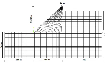
As a case study, two-dimensional model of Watana RCC dam has been chosen. The geometric properties of the model along with the foundation and reservoir have been displayed in Figure1 in which, all the dimensions are in meters. Modulus of elasticity, weight per volume, and Poisson's ratio of fresh concrete are respectively 25 GPa, 2500 meter and 0.25; and foundation’s modulus of elasticity is also 37 GPa and Poisson's ratio is 0.30. It should be noted that as foundation, a massless foundation model has been used.
The velocity of pressure waves in water has been considered 1440 with density of 1000 . For the finite element model, the length of the reservoir has been considered as much as three times the dam’s height and the height of the dam is equal to the height of dam’s structure. Sommerfeld boundary condition has been used for the distant, and time step equals to .
To discretize the models of dam and foundation, the element PLANE183 and for water, Fluid29 that is a suitable element to display the fluid compressibility were used. Discretization the finite elements of the model are shown in Figure1 [6]:
FIGURE I.Geometry of the dam model and discretization of finite element
To conductthe dynamic analysis and study the seismic performance of RCC dam, horizontal and vertical accelerograms of Manjil earthquake occurred in 1990 in the region of Gilan in Iran, have been applied. Horizontal and vertical records in the earthquake are as shown in Figure 2 & 3.
FIGURE II. Horizontal accelerograms of Manjil earthquake
FIGURE III. Vertical accelerograms of Manjilearthquake
III. ANALYSIS RESULT
According to the mentioned conditions and analysis of the model, the following results were obtained. By interpreting and analyzing the responses, an appropriate value for the coefficient of Z and according to this value, the optimal values for the stiffness of concrete and bedrock have been obtained. In Fig.4 to 11 the process of changesare-presented well.
In Figure4, displacements of the dam’s crest towards different proportions of the concrete and bedrock hardness are shown:
FIGURE IV. The curve of variation of dam crest displacement against against increase of Z
Regarding to the chart of Figure4, reduction or increase of the dam concrete to the bed rock stiffness (Z) has had invert influence on improvement of the structural displacement over a particular range; and the most desirable and optimal state for minimizing the dam’s displacement is the value of 1.5 for the variable of Z.
Thus, as to minimize the dam’s displacement, the stiffness of dam’s concrete and bedrock is selected 24.67 GPa and 37 GPa in order.
In Figure5, the hydrodynamic pressure changes against the ratio of concrete dam hard bedrock shown:
FIGURE V. The curve of variation of hydrodynamic pressure
against increase of Z
As observed, for hydrodynamic pressure, the range between 0.9 to 1.5 considered as an appropriate and suitable amount, and in this range,the hydrodynamic pressure is minimized.
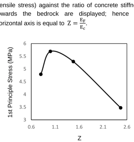
In Figure6, the changes of first major stress (tensile stress) against the ratio of concrete stiffness towards the bedrock are displayed; hence the horizontal axis is equal to .
FIGURE VI. The curve of variation of tensile stress at the heel of dam against increase of Z
According to Figure6, increase or decrease of the ratio of concrete stiffness in response to the bedrock leads to reduce the first principal stress (tensile stress); nonetheless, according to the shape and the permitted amount of the responds the most appropriate scope is 1.5 to 2.1 for the fixed value of Z.
In Figure 7, the changes of third major stress (compressive stress) against the ratio of concrete stiffness in response to the bedrock have been
12 13 14 15 16 17 18 19 20 21
0.5 1 1.5 2 2.5 3
Dis
plac
emen
t
(c
m)
Z
1.4 1.5 1.6 1.7 1.8 1.9 2 2.1 2.2 2.3
0.6 1.1 1.6 2.1 2.6
Hydro
dynamic
Pres
su
re
(MPa)
Z
3 3.5 4 4.5 5 5.5 6
0.6 1.1 1.6 2.1 2.6
1s
t
Princ
iple
St
re
ss
(MPa)
Vol. 2 Issue 3, March - 2016
FIGURE VII. The curve of variation of compressive stress at the toe of against increase of Z
According to the high compressive strength of concrete for the response of the third principal stress, the optimum respond value is selected 1.2 to 2.1 regarding to other structure’s responds for the coefficient of Z.
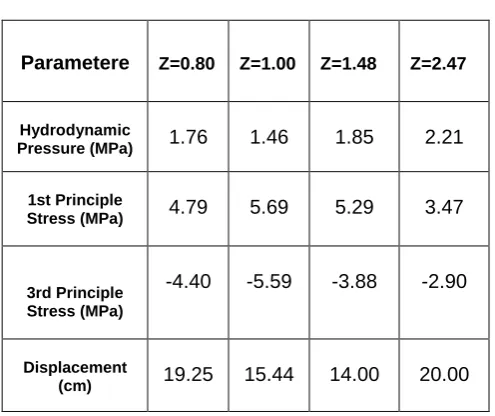
The following summarizes the results of the analysis are shown in Table 2 that by taking a different amount of hard structural response in different coefficients of concrete dam to the bedrock, the optimal amount is provided:
TABLE I. The value of results for different proportions of dam concrete to the bedrock stiffness (Z)
Z=2.47 Z=1.48
Z=1.00 Z=0.80
Parametere
2.21 1.85
1.46 1.76
Hydrodynamic Pressure (MPa)
3.47 5.29
5.69 4.79
1st Principle Stress (MPa)
-2.90 -3.88
-5.59 -4.40
3rd Principle Stress (MPa)
20.00 14.00
15.44 19.25
Displacement (cm)
According to the presented table and structure’s response, the most optimal and desirable value for Z is almost 1.5, given that the first principal stress (tensile stress) as well as structural placement play key role in the RCC dams, so that in addition to reducing the dam’s displacement, the tensile stress is controlled as well, and it does not exceed the limit.
IV. SUMMARY AND CONCLUSIONS
According to the diagrams and model analysis responds, the following results were obtained:
1. Determination of exact relation between the stiffness of the concrete dam and bedrock is an important issue in the design and analysis of RCC dams.
2. Being rigid is not necessarily a good measure for analysis and a proper ratio of rigidity must be identified.
3. The most optimal mode for the ratio of dam concrete and the bed rock stiffness in the analysis of this model is 1.50, thus the amount of the dam’s concrete stiffness and bedrock is obtained as follows.
4. Considering these values, the optimal values for the responds of the dam crest displacement and tensile stress that play a decisive role in the design are achieved.
REFERENCES
[1] Y. Calayir, and M. Karaton, “Two-dimensional seismic analyses of Koyna gravity dam are performed by using the 1967 Koyna,” Computers & structures, 2005, 83(19-20), pp.1595-1606.
[2] Z. Chuhan, W. Guanglun, W. Shaomin, and D. Yuexing, “Experimental Tests of Rolled Compacted Concrete and NonlinearFracture Analysis of Rolled CompactedConcrete Dams,” Journal of Materials in Civil Engineering, 2002, 14(2), pp. 108-115.
[3] D. R. Y Singh, and A. S. Chauhan, “Neural networks in data mining,” Journal of Theoretical and Applied Information Technology, 2009, 15(1), 37-42.
[4] A. K. Chopra, and P. Chakrabarti, “The Koyna earthquake and the damage to Koyna Dam,” Bulletin of the Seismological Society of America. 1973, 63(2), 381-397.
[5] O.C. Zienkiewicz, and P. Bettess, "Dynamic fluid-structure interaction: Numerical modeling of the coupled problem," John wiley, New york, 1978, pp.185-193.
[6] Ansys user manual, Release 11.0 Documentation for Ansys, SAS IP, Inc; 2007.
-6 -5.5 -5 -4.5 -4 -3.5 -3 -2.5
0.6 1.1 1.6 2.1 2.6
3r
d
Princ
iple
St
re
ss
(MPa)