Author for correspondence:
1Student, Department of Mechanical Engg (CAD/CAM), Holy Mary Institute of Technology and Science,
Volume-5 Issue-4
International Journal of Intellectual Advancements
and Research in Engineering Computations
Impact analysis of a car bumper using classical ansys
Resu Rachana
1, Pedamuthevi Vijayanand
2,
Jothi Murugan
31
Student, Department of Mechanical Engg (CAD/CAM), Holy Mary Institute of Technology and
Science, Hyderabad, Telangana, India
2
Associate Professor, Department of Mechanical Engg, Holy Mary Institute of Technology and Science
Hyderabad, Telangana, India.
3
Associate Professor, Department of Mechanical Engg, Holy Mary institute of Technology and Science
Hyderabad, Telangana, India
ABSTRACT
Car bumper is one of the main part, because it is use to protect Impacts by an accidents. By calculating this impact analysis we are using the software is CLASICAL ANSYS .in this study we taken the most important variable materials shapes and structures and impact situations of conditions are studied for analysis for car bumper in crash divided into parts car bumper is created by impact design using PRO-E and using ansys software. In this ansys we calculate the seed is13.8m/s (50km/hr).To analysis to result and it is used to according of federal motor vehicle safety standards FMVSS 208 .occupants crash protection were by the purpose and scope of these standards specific requirement to protect of cars in this research analysis worked over done. for speed which are is according to regulations and It also by changing varies speeds. Using analysis software of ansys .the material Is used for bumpers is stain less steel
INTRODUCTION
Now a day‟s important fact of cars most dangerous troubles are facing from car drivers in accidents. And we take so much many safety precautions for decrease accidents. Car bumper is the most main role to save and absorb sharks on accidents. By this purpose we are using so many materials in the market. They are plastic, stainless steel, fiber. In these materials we are absorbed the most efficiently materials for create a car bumper the best one is stainless steel. Plastic and fiber was delectated than stainless steel. But it worthy than fiber and plastic. Stainless steel bumper is used for decrease physical body damage of car when with met an accident. This is more strength than others materials and it can easy to repair for recover of vehicle. Car bumper was protect to the headlamps, grills, engine, fuel, exhaust and cooling system and tail lights etc… The car bumper was must have a good design for safety and should it have
low weight. Many countries follow different standards of car bumpers. And most countries car safety system function normal after straight on pendulum moving barrier impact of 4 km/h at 45.5cm above to the ground. It can calculate by also vehicle is loaded or unloaded. The automotive bumpers were changed in the past 60years. It contained performance of a careful design material selection for stiffness and strength for fitness. Strength and energy, energy absorption and fitness were first criterion. Now a day, automotive industries are only concentrate on optimize of safety and weight.
Car Bumper
The materials used for car bumpers have evolved with time. Originally, they were made from electroplated steel then aluminum was used. Starting from the 1980s, plastics were introduced: glass-reinforced polyesters and polyurethanes, modified polypropylene and blends of
thermoplastic polyesters and polycarbonates. Plastic bumpers have the advantage of being lighter than their metal counterparts and they are better able to absorb energy in minor collisions
without permanent damage. Click on the button below to open the case study in CES Selector™ with the Process data module.
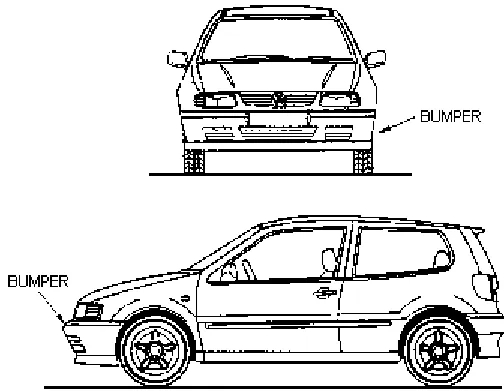
Fig 1.1 car bumper
A typical car bumper is made from glass-reinforced polyester. It weighs between 4 and 10 kg and has a minimum section thickness of 5 mm. The shape could be described as either a sheet (since the thickness is uniform) or a 3-D solid shape. The surface finish for the bumper should be 0.4 μm or better. The design requirements.
CLASSIFICATIONS
OF
CAR
BUMPER
Modern bumpers are made with a combination of materials. The first element is an impact absorbing spring device, usually gas-filled cartridges which mount the front bumper to the chassis. This allows the bumper system to absorb minor impacts without any damage. The next part is the steel or aluminum support structure, which is a lateral beam. On top of that is a honeycomb or egg-crate shaped plastic piece made of HDPE which defines the bumper's ultimate external shape and supports the shape of the bumper cover. On the rear, these can be attached to the cars other bodywork or components. In a more serious accident, this part of the bumper structure is usually the part that is damaged, but not visible. Finally a urethane or other flexible polyethylene plastic bumper cover is applied to the outside to give the car a finished appearance. These are
undamaged. In terms of styling and practicality, many manufacturers used rubber to absorb the impact and protect the chrome metal bumper. I much preferred this to the modern plastic covered sty rofoam and aluminum. The new ones scuff, crack and chip from something as slight as a car hitting it while parking. Here are the top 13 high performance plastics used in automotive hardware. While all 13 may easily be used in a single vehicle, just three types of plastic make up approximately 66% of the total high performance plastics used in a car: polypropylene (32%), polyurethane (17%) and PVC (16%).
Polypropylene (PP)
Polypropylene is a thermoplastic polymer used in a wide variety of applications. A saturated addition polymer made from the monomer propylene, it is rugged and unusually resistant to many chemical solvents, bases and acids. Application: automotive bumpers, chemical tanks, cable insulation, gas cans, carpet fibers.
Polyurethane (PUR)
Solid Polyurethane is an elastomeric material of exceptional physical properties including toughness, flexibility, and resistance to abrasion and temperature. Polyurethane has a broad hardness range, from eraser soft to bowling ball hard. Other polyurethane characteristics include extremely high flex-life, high load-bearing capacity and outstanding resistance to weather, ozone, radiation, oil, gasoline and most solvents. Application: flexible foam seating, foam insulation panels, elastomeric wheels and tires, automotive suspension bushings, cushions, electrical potting compounds, hard plastic parts.
Poly-Vinyl-Chloride (PVC)
PVC has good flexibility, is flame retardant, and has good thermal stability, a high gloss, and low (to no) lead content. Polyvinyl chloride molding compounds can be extruded, injection
molded, compression molded, calendared, and blow molded to form a huge variety of products, either rigid or flexible depending on the amount and type of plasticizers used. Application: automobile instruments panels, sheathing of electrical cables, pipes, doors.
ABS
Acrylonitrile Butadiene Styrene is a copolymer made by polymerizing styrene and acrylonitrile in the presence of polybutadiene. The styrene gives the plastic a shiny, impervious surface. The butadiene, a rubbery substance, provides resilience even at low temperatures‟ variety of modifications can be made to improve impact resistance, toughness, and heat resistance. Application: automotive body parts, dashboards, wheel covers
Polyamide (PA, Nylon 6/6, Nylon 6)
Nylon 6/6 is a general-purpose nylon that can be both molded and extruded. Nylon 6/6 has good mechanical properties and wear resistance. It is frequently used when a low cost, high mechanical strength, rigid and stable material is required. Nylon is highly water absorbent and will swell in watery environments. Application: gears, bushes, cams, bearings, weather proof coatings
Polystyrene (PS)
Naturally clear, polystyrene exhibits excellent chemical and electrical resistance. Special high gloss and high impact grades are widely available. This easy to manufacture plastic has poor resistance to UV light. Application: equipment housings, buttons, car fittings, display bases.
Polyethylene (PE)
Fig 1.2 Car with bumper
TYPES OF CAR BUMPERS
1. Steel bumper 2. Composite bumper 3. Plastic bumper 4. Body kit bumper
The majority of modern plastic car bumper system fascia is made of thermoplastic olefins (TPOs), polycarbonates, polyesters, polypropylene, polyurethanes, polyamides, or blends of these with, for instance, glass fibers, For strength and structural rigidity. Three main design factors for this structure: shape, material and impact condition are studied and the results are
compared with conventional metals like steel and aluminum. In this research, a front bumper beam made of three materials: aluminum, glass mat thermoplastic (GMT) and high-strength sheet molding compound(SMC) is studied by impact modeling to determine the deflection, impact force, stress distribution and energy-absorption behavior The study will focus on existing design performance, advantage and limitations. Based on Observations design improvements will be made in terms of shape & material based on design. Modification objectives. Modified front bumper design will be tested using FEM software for impact loads as per international standards.
Explanations on types of car bumpers
Steel bumper
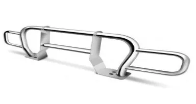
Fig1.3 Steel bumper
The steel bumper used for the entire body of a car, and including the bumper, in this car bumper very heavy and denoted performance, As car engine design has improved. In this steel car
strong in a crushed. But it was very heavy and denoted performance as car engine improved. For example unnecessary damage to the structure of passenger car in low speed crush a 15 kmph 40% over lap test was damaged from 0 degrees to 10 degrees and the rare impact to moving barrier weight was increased from 1000 to 1400 kg .such as sub optimize design or in most cases not robust and often lead to expansion damage car –to –car in this insurance climes date indicate that rear bumpers are often under –ridden by a striking
vehicle due the bumper system to this end bumper should ideally mounted at slightly different heights front and rear but have sufficient heights to maintain engagement over a wide range of circumstances. In this however insurance date also show that rear bumper are over ridden when struck by high ride high vehicles (suv ,pick up trucks) Vehicles damage ability would be improved in both these situations in vehicle bumper should prevent or limit much of the damage sustained in these minor crashes.
Composite bumper
Fig1.4 Composite bumper
The composite bumper present condition of competitive in this fuel economic plays important show in this order to achieve this the searchers or shifted towards light weight bumper such as composite bumper material as carbon fiber is a material con sifting of fibers about 5 – 10 micromere in diameter and composed of carbon
atoms .the carbon fiber is formed by arranging the carbon in this composite bumper advantages of having carbon fiber as bumper is high strength to weight ratio and because of brittleness it dissipates energy by breaking the bumper in ensure passengers safety in comparisons with the steel,
Plastic bumper
Fig1.5 Plastic bumper
More cars are used plastic bumpers. Mostly modern cars are use reinforced thermoplastic bumper. They are cheaper than other to manufacture of bumper and easy to install. And absorb more energy in during a crash. Majority car
Body kit bumper
Fig1.6 Body kit bumper
This kit works a skirt around the entire body of the car. And improve performance by reducing air to drag the car, modified the cars often have a full body kit rather than just a form and rear bumper. These have to be specially purchased and can be made from thermoplastic using kit standard bumper out of carbon fiber.
SOLUTIONS
The ansys used throw the steady, state, transits as solving problems in car bumpers.Car accidents are happening every day. Most drivers are convinced that they can avoid such troublesome situations. Nevertheless, we must take into account the statistics – ten thousand dead and hundreds of thousands to million wounded each year. These numbers call for the necessity to improve the safety of automobiles during accidents. As a result most present-day automobiles have at least safety belts with retractors and airbags [6]. However, car accident does not necessarily mean bodily harm. In a low-speed car accident only physical damage occurs, assuming that basic safety regulations, such as fastened seat belts, are kept.
This work focuses on the application of composite materials in a frontal bumper system. In recent years, composite materials have been more frequently used in industry and they have progressively replaced metal materials. This trend is caused by their high strength (and stiffness) to mass ratio and the ability to produce parts with required mechanical properties. The main objective is to analysis the bumper reinforcement made of composite materials and to compare it
with the original steel bumper reinforcement in terms of its stiffness and damage behavior, and mass reduction.
European car testing
EuroNCAP
EuroNCAP company was founded in 1997 and has two main objectives. Firstly, it provides information about comparable automobile safety rating. Secondly, it tries to motivate producers to improve automobile safety and thereby reduces the number of wounded passengers. This task is progressively fulfilled in conjunction with automobile producers. The testing stems from EEVC (European Enhanced Vehicle-safety Committee) procedures. The tests implemented by EuroNCAP are:
Frontal impact,
side impact,
pole impact,
child protection,
pedestrian protection.
RCAR
RCAR the Research Council for Automobile Repairs, is an international organization that works towards reducing insurance costs by improving automotive damage ability, repair ability, safety and security by low-speed offset car crash test.
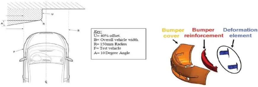
Fig. 4.2. Scheme of RCAR test Fig. 2. Frontal bumper system compo-nents
Bumpers
Bumpers are fixed on the front and on the back side of a car and serve as its protection. They reduce the effects of collision with other cars and objects due to their large deformation zones. The bumpers are designed and shaped in order to deform itself and absorb the force (kinetic energy) during a collision. The whole frontal bumper system consists the following parts:
The cover,
The mechanical and deformation energy
absorber,
The bumper reinforcement.
Composite damage model in PAM-Crash
The Ladev`ezemodelis dedicated to the numerical simulation of unidirectional continuous fiber reinforced composite materials. Unlike the heterogeneous “biphase” model, the Ladev`eze model does not treat the two phases separately (fibers and matrix). Instead the composite ply is described by homogeneous continuum mechanics.
The constitutive relationship of the Ladev`eze model can be expressed as follows [3]:
εe 1/E
1 ν 0 /E1 0 0 0 σ11
11
−
12
e
−
0
0 0 0 σ22
ε
22 ν12
/E
1 1/E2
(1) 2ε12
e
= 0 0 1/G12 0 0
σ
12 ,
2εe 0 0 0 1/G
23
0 σ
23 23
2εe 0 0 0 0 1/G
12
σ
13 13
Where
1. fiber direction: E1 = E10(1 −dft)
2. transverse direction: E2 = E20(1 −d_)
3. for shear: G12 = G 0
12(1 −d)
In these equations dft is the fiber damage constant and d_ and d are the matrix damage constants. Elastic matrix damaging behavior. The matrix related damages are taken into account by two scalar variables, d and d_. These variables express an experimentally displayed phenomena: parameter d quantifies the damage which comes
from the debonding between fibers and matrix, whereas parameter d_ is related to the damage due to the microcracking of the matrix parallel to the fiber direction. The damage functions, Zd and Zd_,
associated respectively with d and d_ are defined by the expressions
∂E
D 1
σ 2
+
σ2
=
Zd =
1 2 13
, (2)
∂
d 2 G120(1 −d)2 ∂
ED =
Z_ =
1 σ22_+ 2
, (3)
∂ d_
d
2 E20(1 −d_)2
Where (2) is shear damage and (3) is transverse damage. ED is elastic strain energy and a_+= a, if a >0, else a
The damage evolution functions over time t are defined as
Yt sup
!
Z (τ ) + bZ (τ )
(4)
( ) = τ ≥t d
d
_
Y _ t sup
!
Z (τ ).
( ) = τ ≥t
d
_
The damage values d and d_ are calculated from
(5)
d=Y(t)−Y0_+ ,Yc
d_=Y(t)−Y0__+ ,Yc_
ifd <dmax, Y_(t) < YS_ and Y (t) < YR, else d =
dmax.
ifd_<dmax, Y_(t) < YS_ and Y (t) < YR, else d_ =
dmax.
(6)
The meanings of the above used quantities are given in Tab. 1.
Table 4.1. Description of damage parameters
YC (Pa)
1/2
Critical shear damage limit value
Y0 (Pa)1/2 Initial shear damage threshold value
YC _
(Pa)1/2 Critical transverse damage limit value
Y0_ (Pa)1/2 Initial transverse damage threshold value
YS_
Interface
(Pa)1/2 Brittle transverse damage limit of the fiber-matrix
YR (Pa)1/2 elementary shear damage fracture limit d
max [–] maximum allowed value of d and d_ (dmax< 1)
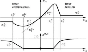
Fiber tensile (compression) damage
The implemented law [3] implies that the fiber damage is null while ε11<εfti, where εfti corresponds
to the initial longitudinal fiber tensile damage threshold strain. Then the tensile fiber damage dft
grows linearly between εfti< ε11<εftu where εftu is the
ultimate longitudinal fiber tensile damage strain. When this ultimate value is reached, the fiber tensile damage dft reaches the ultimate damage, dftu. After
this point the tensile damage grows asymptotically towards dft = 1 (see Fig. 4) PAM-Crash impact model validation. The PAM-Crash software includes many types of material models for composite materials as well as many element types. The Ladev`eze model is chosen in this work for the analysis of impact behavior together with shell elements.
Experimental measurements
A steel impactor was dropped from the height of
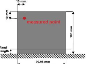
Fig. 4.6. Basic dimensions of composite plate
a) Fig. 4.7. Experimental measurement: a) experimental schema, b) actual photograph from measurement (1 – tube fixture, 2 – impactor guide tube, 3 – composite plate, 4 – optoNCDT lase sensor
Table 4.2. Plate properties Table 4.3. Impactor properties
EL= 109.4GPa E = 210GPa
ET= 7.7GPa = 7 800kg/m
3
GLT= 4.5GPa ν = 0.3
ν = 0.28 diameter d = 4 mm
fixed length = 6 mm length l = 40 mm
plate thickness = 0.8 mm
= 1 579.07kg/m3
Table 4.4. Comparison of failure forces
Force [kN] A00 A45 A90
Experiment 33.28 1.35 1.11
Numerical simulation 32.722 7 1.321 8 1.196 8
The composite plate made of carbon/epoxy (C/E) material consists of four layers of uni-directional composite with orientations [0, 90, 90,0]. The total
Fig.4.8 .Impactor Fig.4.9. Comparison between experimental curves and numerical simulation
Damage analysis
The testing was realized with a rigid barrier, which was pushed against the bumper reinforce-ment and the deformable elereinforce-ment, (see Fig. 12) by a prescribed displacement. The parameters of the
simulation barrier are equal to the barrier used in RCAR tests as introduced in section 2.2, i.e., rigid barrier with an inclination of 10 degrees, shift of the barrier is 40 % of the maximum width of the car without mirrors. The results are displayed in Fig. 13.
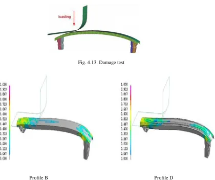
Fig. 4.13. Damage test
Profile B Profile D
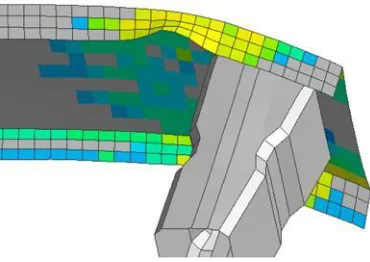
Fig. 4.15. The fracture initiation on the edge of modified profile B
The analysis revealed fracture on the edge of the profile B, see Fig. 14, which does not demonstrate a good damage behavior of the bumper reinforcement. The modified profile D proved to be the best of all tested profiles. The maximum value of damage in
the simulation is about 60 % (maximum dmax value
in the whole model). This means that the loading is still transferred to the deformable element (see Fig. 2) which is necessary feature for a well-designed bumper reinforcement.
Table 6. Bumper reinforcement mass comparison
Material Mass [kg]
original steel 8.89
composite profile A 1.14 modified composite profile B 1.63
composite profile C 1.45
modified composite profile D 1.94
Material Speed Disp Stress Strain 48km/hr 0.317229 1053.78 0.002165 Steel 75km/hr 0.496801 1645.34 0.0033870
150km/hr 0.999592 3218.56 0.0064334
ANSYS SOFTWARE
Material Speed Disp Stress Strain 48km/hr 0.297715 25.4296 0.00865195
Plastic 75km/hr 0.452602 39.6692 0.0118735
150km/hr 0.916127 78.9181 0.023666
Material Speed Disp Stress Strain 48km/hr 0.31642 169.485 0.0025749
PEI 75km/hr 0.494451 264.538 0.0040749
150km/hr 0.983933 513.814 0.0080296
OBJECTIVE OF THE PROJECT
The aim of this work has what is the study of bumper by using classical ANSYS.
Passenger car in forms of material selection using impact analysis to analyze mechanical properties of using inn front part of car bumper by speed impact analysis.
To analyze on the mechanical properties on focus by stress analysis.
To modeling the actual dimension of the car bumper into the ansys software and analyze by using impact load.
SCOPE OF THE WORK
In this project we have modules a car bumper using ANSYS software.Impact analysis is be done by on the car bumper of in a different speed of 48 km/h , 75km/h 150 km/h the analysis is conduct on the car bumper for different materials.Steel stainless, fiber, plastic, reinforced, present used materials for car bumper. Is steel we are replacing with ABS plastic and carbon fiber the density of ABS.
RESULTS AND CONCLUSION
Result
In the solution as been many ways of present ansys in a car bumper design used to tables, graphs, contour plot.This process as research as the bumper as changing to the different materials , in this used to (finite element method ) FEM has to the using to FE COAD ANSYS Of bumper process manilyrequed to the quality , criteria ,analysis , as most.In this process as used to the ansys software ,here the design of analysis process .As requed to the bumper beam as automotive application . its depends on topography process .Its used to the carry the stell material as for using manufacturing process,Bumper as the longitudinal process ,its used through the numerical process also similarly this bumper beam as the all components as meshed in order modal process , here the different type of bumper.
Fig.7.1 bumper beem model
CONCLUSION
In this project we have explored some of the ways in which the structure of the life world supports agents' cognition, and we have suggested how this analysis might be expanded to cover a wider range of phenomena. Much work obviously remains to be done. Perhaps the most significant part of this work concerns a fundamental assumption of life world analysis: that people use objects in customary ways. This is a plausible enough first approximation, but it is not always true. Faced with a difficulty that goes beyond the capacities of the usual practices and the artifacts that are readily
REFERENCES
[1]. H. S. Park, X. P. Dang, A. Roderburg, “Development of Plastic Front Panels Of Green Cars” CIRP Journal of Manufacturing & Technology 26, 35-53
[2]. Kuziak .R. Kawalla, R.waengler.s. “Advanced high strength materials for automotive industry A review” Journal of Archives of Civil & Mechanical engineering. 8(2), 2008, 12-30, 103-117
[3]. Falaichen , Bert Juttler, “Geometric Modeling & Processing”, Journal on CAD, 42(1), 1- 15
[4]. David H. Allen “Structural Analysis, Aerospace” Journal on Encyclopedia of Physical science and technology 3rd edition 2003
[5]. Japan.s.Daniel.L. and Theodor .k.2005. “Finite Element Analysis of Beams”, Journal of Impact engg. 31, 861-876., 155-173.