Author for Correspondence:
1PG Scholar,CAD/CAM Engineering, KSR Institute For Engineering & Technology, Tiruchengode, Tamilnadu, India.
APR-2015
International Journal of Intellectual Advancements
and Research in Engineering Computations
DESIGN AND MATERIAL OPTIMIZATION OF I.C ENGINE PISTON
USING ANSYS
1
K.V.Karthick,
2S. Ponnusamy
ABSTRACT
The Piston is a „heart‟ of an automobile engine. The piston is a major part of IC engine which is used to transmit the power from combustion chamber to crank shaft without piston engine could not run. The use of a piston is mostly found in automobiles. A little consideration will show that in order to reduce the piston material. In this project, the analysis on piston of an IC engine is done.
The detailed analytical design of piston is calculated and discussed, and then three dimensional model of the piston was created by using calculated parameters using Cero Parametric 2.0 software and finite element analysis (FEA) is performed to obtain the variation of stress at critical locations of the piston using the ANSYS 14.0 software.
INTRODUCTION
The Piston is a „heart‟ of an automobile engine. It‟s one of the key components of the engine and it‟s working the hard condition. The function of the piston is bearing the gas pressure and making the crankshaft rotation through the piston pin. Piston works in high temperature, high pressure, high speed and poor lubrication conditions. Piston contact with high temperature gas directly, the instantaneous temperature can be high. Because of the high temperature and the poor cooling condition, the temperature of the top of the piston can be reach certain level when the piston working in the engine. And the temperature distribution is uneven. The top of the piston bears the gas pressure, in particular the work pressure. The investigations indicate that
greatest stress appears on the upper end of the piston and stress concentration is one of the mainly reason for failure.
In this study, the piston is used in low idle and rated speed engine. In order to enhance the engine dynamic and economic, it is necessary for the piston to implement optimization. Based on the analysis of optimal result, the stress concentration on the upper end of piston has become evaluate, which provides a better reference for redesign of a piston. As one of the major moving parts in the power-transmitting assembly, the piston must be so designed that it can withstand the extreme heat and pressure of combustion. It also transmits heat to the cooling oil and some of the heat through the piston rings to the cylinder wall.
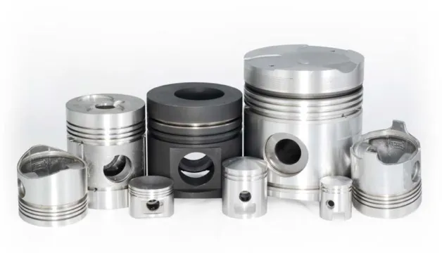
Fig 1.1 Pistons
DESCRIPTION
In engine the piston is the major part. The weight reduction of the piston can have a certain role in the weight reduction of the engine and is a highly desirable goal if it can be achieved without increased in cost and decrease in quality and reliability. It is possible to achieve a design of piston with less weight to increase the strength and decrease in stresses which can be done by design and material optimization of the piston.
AIM AND SCOPE OF THE WORK
This work deals with conventional aluminium alloy IC engine piston.
FUNCTIONS OF PISTON
The functions which a piston is called to perform in an IC engine are;
To transmit the force of explosion to the crankshaft.
To form a seal so that the high pressure gases in the combustion chamber do not escape into the crankcase.
To serve as a guide and a bearing for small end of the connecting rod. Apart from its capability to perform the above functions efficiently the pistons must have some other desirable characteristics.
The design should be such that the seizure does not occur.
It should offer sufficient resistance to corrosion due to some other products of combustion.
It should have the shortest possible length so as to decrease overall engine size.
It should be lighter in weight so that inertia forces created by its reciprocating motion are minimum.
Its material should have a high thermal conductivity for efficient heat transfer so that higher compression ratios may be used without occurrence of detonation.
It must have a long life.
MATREIALS AND
CONSTRUCTIONAL FEATURES
have flat head as shown. In some such pistons which come quite close to the valves, the head is provided valve relief. Pistons used in some high powered engines have a raised dome which is used to increase the compression ratio as well as to control combustion.
In some other engines the piston may be dished to form a desired shape of combustion chamber, jointly with cylinder head. In case of piston containing part of the combustion in its crown, compression ratio can be controlled very accurately but the disadvantage is that in this case much larger amount of heat has to be dissipated through the pistons and rings.
Towards the top of the piston of a few grooves are cut to house the piston rings. The bands left between the grooves are known as lands. These lands support the rings against the gas pressure and guide them so that they may flux freely in the radial direction. The supporting webs transmit the force of explosion directly from the crown to the piston pin bosses thereby relieving the groove portion of the large load and thus by preventing the deformation of the ring grooves.
The part of the piston below the rings is called skirt. Its function is to form a guide suitable for absorbing side thrust due to gas pressure. The side thrust is produced on account of the inclination of the connecting rod with the cylinder axes. The skirt is provided with the bosses on the inside of the piston pin. It must be of sufficient length to resist tilting of the piston under load. It is kept quite close fitting in the cylinder but even then it is separated from the cylinder walls by means of lubricating oil film for smooth running. The combustion pressure from the piston crown is transmitted to the connecting rod through webs inside the piston. The bosses form a bearing surface for the rocking motion of the connecting rod. The thick-sectioned webs also form heat paths from the piston crown to the pin bosses and the skirt and thus have to be designed so as to avoid expansion problems.
The distance between the axis of the piston pin and the top of the piston crown is called
compression height and determines the compression ratio for a given engine. Thus the same engine a piston with lesser compression height would give lesser compression ratio and vice versa.
The material used for pistons at one time was cast iron which has good wearing qualities. As the technology developed Aluminium alloy containing silicon replaced cast iron as piston material, because of two distinct advantages. Firstly it is as much as three times lighter than the cast iron which makes it is desirable from inertia point of view.
Secondly it possesses a higher thermal conductivity which causes it to run cool. But the aluminium alloy has its own advantages. It is not as a stronger as cast iron and hence thicker sections have to be used. As a result of which the weight of piston is increased. It is seen that an aluminium alloy piston in actual practice is only about 50 percent in weight as compared to its cast iron counterpart. Further aluminium alloy is relatively soft as a result of which fine particles in the lubricating oil become embedded it. Aluminium alloy piston with fine particles embedded in it causes a sort of grinding or abrasion of the cylinder walls thus shortening cylinder life. Another important drawback of using aluminium alloy pistons for cast iron cylinders is their unequal co efficient of expansion which causes engine slaps. Because if the cold clearance is kept just sufficient there is danger of seizure at operating temperatures and if cold clearance is kept large the engine knocks or slaps when cold. This difficulty has been overcome by different methods. Some of the functions are
barriers and so reduce even more the amount of heat reaching the working faces of the skirt. Moreover the drooping end makes the skirt flexible in the upper region. Making a heat dam. It consists of a groove cut near the top of the piston. This reduces the path of heat travel from the piston crown to the skirt. The skirt therefore runs cooler and does not expand much.
Use of vertical t slots; vertical or t slots on the non linear side of the piston were earlier used quite commonly. However the mechanical strength is decreased on account of slot. Moreover with the slot the skirt tends to collapse inwards without elastic recovery. As result the diameter is reduced permanently which increases the piston slap, instead of decreasing it.
Taper pistons: the piston are sometimes turned taper the crown side being smaller in diameter than the skirt end. As higher temperatures occur towards the crown than the side expands more than the skirt due to which the piston diameter becomes uniform under running conditions.
Cam ground pistons; the pistons are cam ground such that they have elliptical section instead of the usual circular one. The minor diameter of the ellipse lies in the direction of the piston pin axis. Such pistons after expanding at operating temperatures become circular automatically the more expansion along minor axis being caused by the metal of piston bosses there. Generally tapered and ovality are combined in the same piston. The amount of ovality is kept maximum at the piston pin boss level and is reduced gradually towards the bottom of the skirt.
Use of special alloys; special alloys having low efficient of expansion or rather whose coefficient of expansion is nearly equal to that for cast iron have been used in the manufacture of pistons without split or specially shaped skirts and giving no piston slap.
SELECTION OF MATERIALS
ALUMINIUM ALLOYS
ALUMINIUM ALLOYS VERSUS TYPES OF STEEL
Aluminium alloys typically have an elastic modulus of about 70 GPa, which is about one-third of the elastic modulus of most kinds of steel and steel alloys. Therefore, for a given load, a component or unit made of an aluminium alloy will experience a greater elastic deformation than a steel part of the identical size and shape. Though there are aluminium alloys with somewhat-higher tensile strengths than the commonly used kinds of steel, simply replacing a steel part with an aluminium alloy might lead to problems.
With completely new metal products, the design choices are often governed by the choice of manufacturing technology. Extrusions are particularly important in this regard, owing to the ease with which aluminium alloys, particularly the Al–Mg–Si series, can be extruded to form complex profiles of engine components like piston.
In general, stiffer and lighter designs can be achieved with aluminium alloys than is feasible with steels. For instance, consider the bending of a thin-walled tube: the second moment of area is inversely related to the stress in the tube wall, i.e. stresses are lower for larger values. The second moment of area is proportional to the cube of the radius times the wall thickness, thus increasing the radius (and weight) by 26% will lead to a halving of the wall stress. For this reason, bicycle frames made of aluminium alloys make use of larger tube diameters than steel or titanium in order to yield the desired stiffness and strength. In automotive engineering, cars made of aluminium alloys employ space frames made of extruded profiles to ensure rigidity. This represents a radical change from the common approach for current steel car design, which depends on the body shells for stiffness that is a unibody design.
of such engines is critical. Manufacturing techniques and metallurgical advancements have also been instrumental for the successful application in automotive engines. In the 1960s, the aluminium cylinder heads of the Corvair earned a reputation for failure and stripping of threads, which is not seen in current aluminium cylinder heads.
An important structural limitation of aluminium alloys is their lower fatigue strength compared to steel. In controlled laboratory conditions, steels display a fatigue limit, which is the stress amplitude below which no failures occur – the metal does not continue to weaken with extended stress cycles. Aluminum alloys do not have this lower fatigue limit and will continue to weaken with continued stress cycles. Aluminium alloys are therefore sparsely used in parts that require high fatigue strength in the high cycle regime (more than 107 stress cycles)
ALUMINIUM ALLOY MATERIAL
COMPOSITION
Aluminium alloy (Al-Mg-Si) alloys had already been developed in the 1920s. They can be hardened by „artificial‟ ageing – i.e. by baking the solid solution at 150°C to 180°C after quenching. Such alloys are now widely used versatile materials due to their potential to be aged to medium strength while having good metal forming properties in the non-aged state. In addition, corrosion and welding properties are reasonable, costs are moderate and handling is simple. They have found many applications in the transport industry (automotive, railway), architecture and consumer goods industry.
Aluminium alloy have a many grades. Every grade has different characteristics. The common characteristics of all grades of Aluminium alloy are
Light
Strong
High strength-to-weight ratio
Resilient
Ductile at low temperatures
Corrosion resistant
Non-toxic
Heat conducting
Reflective
Electrically conducting
Non-magnetic
Non-sparking
Non-combustible
Highly recyclable
Excellent conductor of both heat and electricity
Low mechanical properties
Excellent workability
DIFFERENT ALUMINIUM ALLOY GRADES
1 series : Aluminium of minimum 99% purity 2 series : Alloyed with Copper - Increases strength and improves machinability
3 series : Alloyed with Manganese - Increase strength and hardness
4 series : Alloyed with Silicon - Improves ductility 5 series : Alloyed with Magnesium - Improves strength and corrosion resistance
6 series : Alloyed with Magnesium and silicon - Improve stability to cast and corrosion resistance 7 series : Alloyed with zinc - Reduces ability to be cast and improves strength
8 series : Alloyed with other elements
APPLICATIONS OF ALUMINIUM ALLOY
Aerospace Automotive Marine Rail Building Packaging
Mechanical industry and engineering
Energy distribution
Sports
CHEMICAL COMPOSITION OF ALUMINIUM ALLOY IN PISTON
Magnesium - 0.65%
Silicon - 0.7 %
Table3.1 AL-Mg-Si > Constants
Structural
Young‟s Modulus 2.3e+005 MPa
Poisson‟s Ratio 0.24
Density 2.707e-006 kg/mm2
Thermal
Thermal conductivity 0.77 W/mm oc
Specific Heat 892 J/Kg oc
PISTON SKETCH
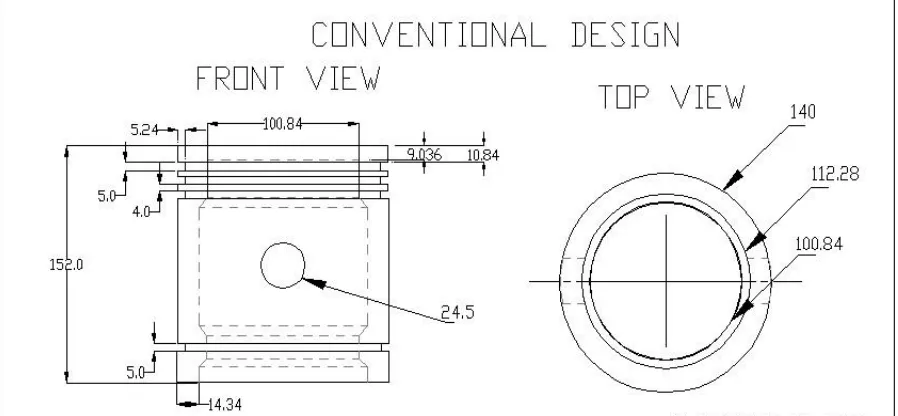
CONVENTIONAL PISTON SKETCH
Fig 5.2 Conventional Piston Sketch Pro-E 2d
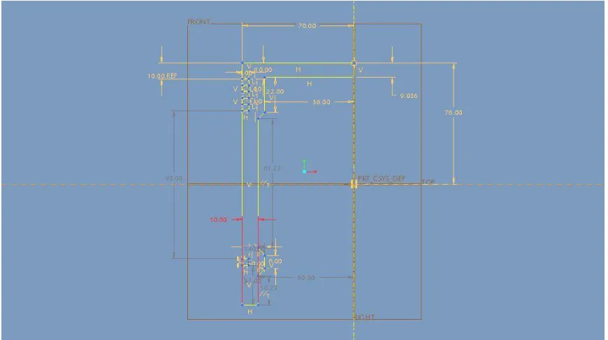
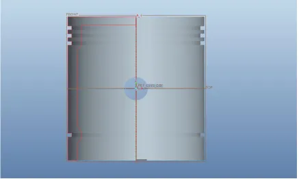
OPTIMIZED PISTON SKETCH
Fig 5.4 Optimized Piston Sketch 2d
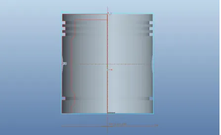
Fig 5.6 Optimized Piston Sketch Pro-E 3d
STATIC STRUCTURAL ANALYSIS
DEFINITION OF STATIC ANALYSIS
A static analysis calculates the effects of steady loading conditions on a structure, while ignoring inertia and damping effects, such as those caused by time-varying loads. A static analysis can, however, include steady inertia loads (such as gravity and rotational velocity), and time-varying loads that can be approximated as static equivalent loads (such as the static equivalent wind and seismic loads commonly defined in many building codes).
LOADS IN A STATIC ANALYSIS
Static analysis is used to determine the displacements, stresses, strains, and forces in structures or components caused by loads that do not induce significant inertia and damping effects. Steady loading and response conditions are assumed; that is, the loads and the structure's response are assumed to vary slowly with respect to time. The kinds of loading include:
Externally applied forces and pressures
Steady-state inertial forces (such as gravity or rotational velocity)
Imposed (non-zero) displacements
Temperatures (for thermal strain)
OVERVIEW OF STEPS IN A STATIC
ANALYSIS
The procedure for a static analysis consists of three main steps:
1. Build the model.
2. Apply loads and obtain the solution. 3. Review the results.
TRANSIENT THERMAL ANALYSIS
DEFINITION OF TRANSIENT THERMAL ANALYSIS
calculates as input to structural analyses for thermal stress evaluations. Many heat transfer applications-heat treatment problems, nozzles, engine blocks, piping systems, pressure vessels, etc.-involve transient thermal analyses.
A transient thermal analysis follows basically the same procedures as a steady-state thermal analysis. The main difference is that most applied loads in a transient analysis are functions of time. To specify time-dependent loads, you first divide the load-versus-time curve into load steps. Each "corner" on the load-time curve can be one load step, as shown in the following sketches.
For each load step, you need to specify both load values and time values, along with other load step options such as stepped or ramped loads, automatic time stepping, etc. You then write each load step to a file and solve all load steps together. To get a better understanding of how load and time stepping work, see the example casting analysis scenario in this chapter.
TASKS IN A TRANSIENT THERMAL
ANALYSIS
The procedure for doing a transient thermal analysis has three main tasks:
Build the model.
Apply loads and obtain the solution.
Review the results.
ANALYSIS PROCEDURE
ANALYZING THE PISTON – STEP BY STEP PROCEDURE
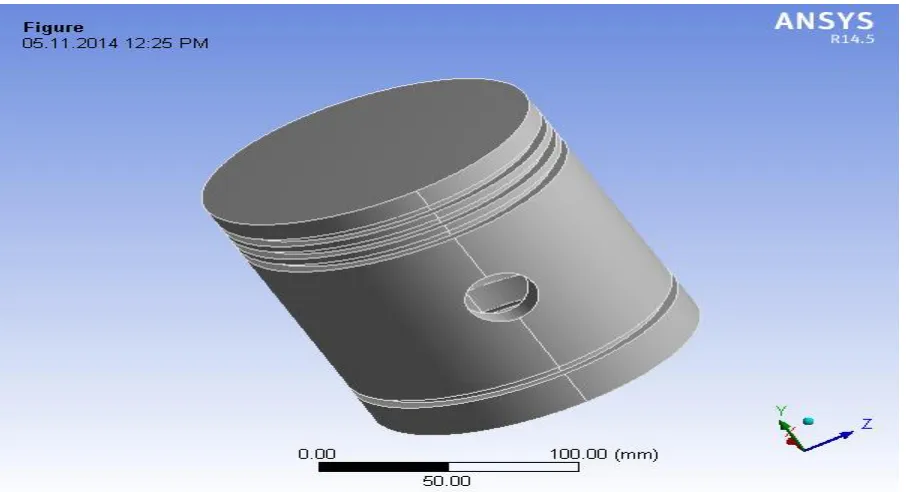
The 3D model of the piston is designed by using pro-e software and it is converted as IGES format.
The IGES (Initial Graphic Exchange Specification) format is suitable to import in the ANSYS Workbench for analyzing
Open the ANSYS workbench
Choose static structural
Go to engineering data
Provide the required materials.
Go to geometry
File – import external geometry file – generate
Close the window
Go to model
Click mesh
Under mesh details, choose sizing – relevant center – fine
Right click the mesh in tree view – generate mesh
Click static structural
Static structural – right click – insert – fixed support
Select the inner circular face of the pin hole
Geometry – apply
Static structural – right click - insert – load - pressure – select the top face.
Geometry – apply
Then define the solution
Solution – right click - insert the total deformation, equivalent elastic strain, and equivalent stress.
Right click the solution icon in the tree – solve
To capture the figure use the option new figure in tool bar.
The all results are taken in a picture – and save it to the required folder in the system
INPUTS AND RESULTS
INPUTS
Fig 10.1 Geometry Imported View in Ansys Workbench
Fig 10.3 Boundary Conditions
RESULTS
EXISTING DESIGN-ALUMINIUM ALLOY
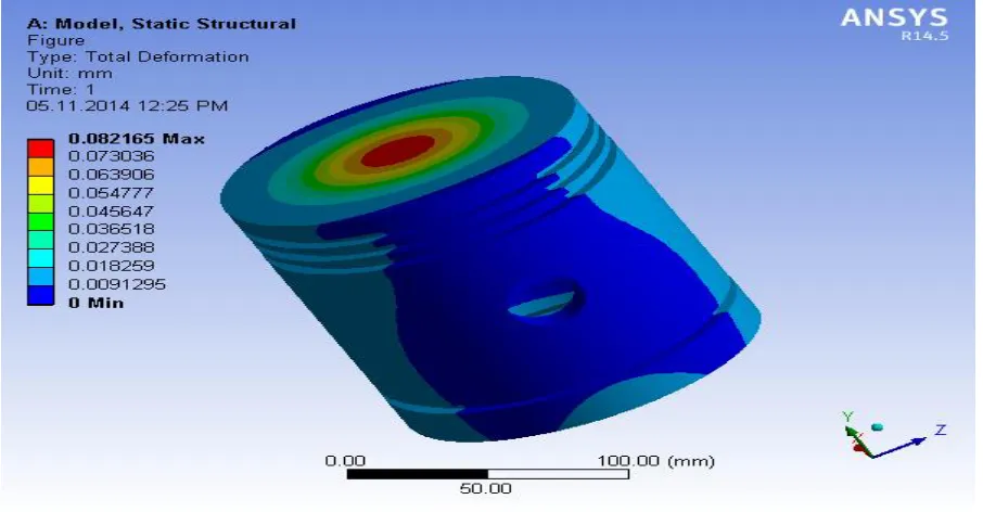
Fig 10.4 Deformation
Fig 10.5 Strain
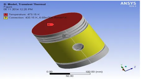
Fig 10.7 Thermal Inputs
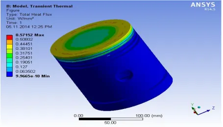
Fig 10.9 Heat Flux
OPTIMIZED DESIGN - ALUMINIUM ALLOY
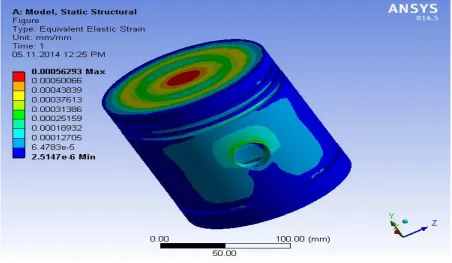
Fig 10.11 Strain
Fig 10.13 Temperature Distribution
TABULATION
Table11.1 Existing Design
MATERIAL TOTAL DEFORMAION Mm Max STRAIN (mm/mm) Max STRESS (MPa)
ALUMINIUM 0.13325 7.48e-4 52.522
Table 11.2 Optimized Designs
MATERIAL TOTAL DEFORMAION Mm Max STRAIN (mm/mm) Max STRESS (MPa)
ALUMINIUM 0.08217 5.63e-4 39.968
CONCLUSION
In IC engine piston plays very important role to transmit power from combustion chamber to crank shaft. So the piston is very important in IC engine. Finite Element analysis of the piston has been done using FEA tool ANSYS Workbench. From the above analysis, the weight reduction has been achieved by both design and material optimization. The weight reduction that is been achieved by 26.59 %.
From this project, study about the analytical calculation of mechanical component and the Analysis software (ANSYS workbench) and 3D-Modelling software (PRO-E) are useful to develop my basic knowledge on piston in IC engine.
REFERENCES
[1]. Wikipedia Piston.
http://en.wikipedia.org/wiki/Piston.
[2]. Ch.Venkata Rajam, P.V.K.Murthy, M.V.S.Murali Krishna, G.M.Prasada Rao “Design Analysis and Optimization of Piston using CATIA and ANSYS”
International Journal of Innovative Research in Engineering & Science.
[3]. Vijay Kumar Paluri “3D Modeling & Detailing of Aluminium Piston With Static Analysis” International Journal of Science Engineering and Advance Technology. [4]. A.R.Bhagat, Y.M.Jibhakate “Thermal
Analysis and Optimization of I.C. Engine Piston Using finite Element Method” International Journal of Modern Engineering Research.