Task-based Dynamic Fault Tolerance for
Humanoid Robot Applications and
Its Hardware Implementation
Masayuki Murakami
Department of Systems Engineering, The University of Electro-Communications, Chofu, Japan Email: [email protected]
Abstract— This paper presents a new fault tolerance scheme suitable for humanoid robot applications. In the future, various tasks ranging from daily chores to safety-related tasks will be carried out by individual humanoid robots. If the importance of the tasks is different, the required dependability will vary accordingly. Therefore, for mobile humanoid robots operating under power constraints, fault tolerance that dynamically changes based on the importance of the tasks is desirable because fault-tolerant designs involving hardware redundancy are power intensive. In the proposed fault tolerance scheme, a duplex computer system switches between hot standby and cold standby according to each individual task. However, in mobile humanoid robots, a safety issue arises when cold standby is used for the standby computer unit. Since an unpowered unit cannot immediately start to operate, a biped-walking robot falls down when failover occurs during cold standby. This paper proposes a safety failover method to resolve this issue and describes the hardware design of the safety failover subsystem.
Index Terms— task-based dynamic fault tolerance, duplex computer system, safety, humanoid robot
I. INTRODUCTION
Although the performance of humanoid robots has advanced remarkably, there is still much scope to improve their dependability. Dependability is a global concept that subsumes reliability, availability, safety, integrity, maintainability, etc. [1]. Most studies on the dependability of humanoid robots deal with the safety mechanism to prevent the robots from damaging themselves and sur-rounding objects and from injuring humans. For example, a humanoid robot that is walking should promptly stop when a human suddenly approaches the robot. Refer-ences [2] and [3] present real-time motion modification methods for emergency stops. For biped humanoid robots, the risk of falling down cannot be eliminated in practical scenarios. Reference [4] describes planning the falling motion of a humanoid robot in order to minimize the damage when it falls down.
The dependability of humanoid robots is subject to the fault tolerance of their computer units. If the main
This paper is based on “Task-based Dynamic Fault Tolerance and its Safety Considerations in Humanoid Robot Applications,” by M. Murakami, which appeared in the Proceedings of the 2007 IEEE In-ternational Conference on Systems, Man and Cybernetics (SMC 2007), Montreal, Canada, October 2007. c°2007 IEEE.
of humanoid robots, an appropriate safety operation should be determined for each task; i.e., a dynamic fail-operational/fail-safe scheme is required. Thus, we propose a task-based dynamic fault tolerance scheme, in which the standby mode of redundant computer units and the safety mode of the system change with each individual task. In this paper, a duplex computer system that switches dynamically between hot standby and cold standby is presented. We designed the redundancy controller that is a key component in the system. It arbitrates the failover process between the two computer units and ensures the safety of the robot when failover occurs during cold standby.
This paper is organized as follows. Section II describes the electrical hardware of humanoid robots. In Section III, hardware redundancy techniques used in high-availability computer systems are reviewed, their applicability to com-puter systems used in humanoid robots is discussed, and the proposed task-based dynamic fault tolerance scheme is presented. Section IV describes the implementation of the proposed scheme. In Section V, the hardware design of the redundancy controller is presented, and the safety failover of this controller is demonstrated by using a duplex system in which it is embedded. Finally, Section VI presents the conclusions of the study.
II. ELECTRICALHARDWARE OFHUMANOIDROBOTS
Recently developed humanoid robots have a hard-ware structure based on a distributed control system. By connecting a local controller to each joint servo and positioning them close to each other, it is possible to improve the noise tolerance in the communication line between the central controller and each servo and minimize malfunctions caused by the disconnection of wires. Moreover, the distributed control system facilitates the maintenance of the robots. Bischoff and Graefe [9] proposed design principles for robotic systems with a focus on dependability and developed a humanoid service robot named HERMES. The hardware of HERMES was designed on the basis of modularity in order to enhance the maintainability and availability of the system. The modular architecture and use of commercial-off-the-shelf (COTS) modules enable quick and easy replacement. In HERMES, an industrial PC is used, and a standardized CAN bus connects all the drive modules to the main computer.
Humanoid robots must be controlled in real time while processing a large amount of information. Hence, many humanoid robots contain multiple computer units, each of which has different functions. For example, in the humanoid robot iSHA with two computer units [10], one unit has real-time control capabilities and controls the actuators, while the other unit is engaged in image processing and in the processing of the data acquired from sensory receptors. HRP-2 [5] also secures real-time control capabilities by using two computers. ARMAR-III [11] has a computer architecture that comprises three processing layers: task planning, task coordination, and
Unit 1
Unit 2
Unit 3
Voter Majority Input
Comparator 1 Comparator 2 Comparator 3
Error_1 Error_2 Error_3 Output
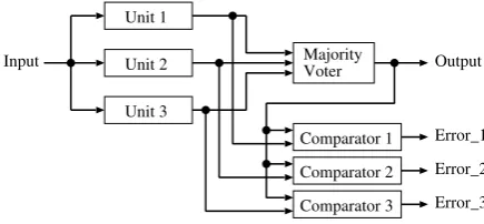
Figure 1. The TMR system with comparators.
task execution. Two industrial PCs and three PC/104 modules are used in these processing layers.
New technology used in the field of industrial automa-tion has been adopted in the development of electrical hardware for humanoid robots [12]. This is an attempt to resolve two technical challenges encountered when trying to commercialize humanoid robots. One is the reduction of hardware costs and development costs, and the other is the improvement of reliability. In the past, industrial automation systems were developed using original tech-nology. However, recent global trends toward increased openness and low costs have decreased the significance of dedicated hardware based on original specifications, and currently, industrial automation systems are required to be constructed using general hardware/software com-ponents while ensuring reliability. Many humanoid robot engineers have adopted a CAN bus for use as a distributed control network in their robots. The CAN bus is a communication standard that has spread widely in the area of industrial automation. As an attempt to further improve the real-time control performance of humanoid robots, engineers have adopted real-time Ethernet [13]. It is very attractive because it enables high-speed communication and its components are not expensive.
III. CONSIDERATIONS FORFAULTTOLERANCE IN COMPUTERSUSED INHUMANOIDROBOTS
A. Hardware Redundancy
Fault tolerance — the ability of a system to continue its normal operation in the presence of faults — determines system reliability and availability and is related with safety. Fault-tolerant systems are realized through redun-dancy in hardware, software, information and/or computa-tions [14]. Hardware redundancy is essential for achieving high system availability; it enables a system to recover from permanent hardware failure. There are two types of hardware redundancies — passive and active. Each redun-dancy scheme is discussed below.
Unit 1A Unit 1B
Unit 2A Unit 2B
Comparator 1
Comparator 2
Switch
Error_1
Error_2
Input Output
Figure 2. Basic pair-and-spare structure with four identical units.
unit. Fig. 1 shows a triple modular redundancy (TMR) system with comparators. A beneficial property of passive redundancy is that continuous operation is guaranteed because any fault within the redundant units does not result in a delay, unless the number of faulty units exceeds the tolerance of the voting. Therefore, many real-time systems demanding continuous operation have been based on the passive redundancy architecture.
Active redundancy is characterized by detecting faults and undertaking some action for recovery. There are many techniques for fault detection. An effective detection method is module or component replication with compar-ison. After fault detection, the system must be accurately and quickly recovered. Standby sparing is the typical form of system recovery. Active redundancy systems with standby sparing comprise one operational unit and one or more standby units. When a fault is detected in the operational unit, the faulty unit is replaced with a standby unit. This switching is termed as failover. The possibil-ity that some fault prevents the system from activating a standby unit or results in the activation of multiple operational units must be minimized by the system de-signers. The speed of failover is the factor that determines the system availability. Unlike passive redundancy, most active redundancy systems have a failover delay. However, few real-time dependable systems demand zero delay at failover. Humanoid robots are not considered as severe time-critical applications because they are not required to have higher performance than the speed of human behavior.
Standby sparing schemes are categorized as hot standby and cold standby. In hot standby, the standby unit is powered on and ready to be operational. In cold standby, the standby unit is powered off or idle. High-availability systems use hot standby, by which a short failover time is realized. “Pair and spare” is often employed in high-availability computer systems. Fig. 2 represents the basic pair-and-spare structure with four identical units. Ref-erence [15] describes hardware redundancy of a drive-by-wire system, and proposes a pair-and-spare system to utilize COTS controllers. Therefore, four COTS con-trollers are used as redundant units. In terms of the power consumption and size, the TMR system is more advantageous than the pair-and-spare system when COTS units are used.
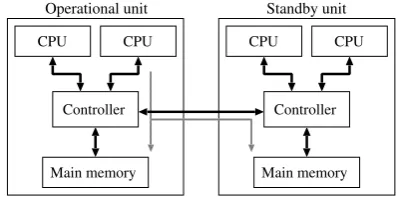
Fig. 3 illustrates a typical implementation of the pair-and-spare technique. The system has one standby unit and four CPUs in total. The central controller in the
Main memory
Operational unit Standby unit
Controller
CPU CPU
Main memory Controller
CPU CPU
Figure 3. Typical implementation of the pair-and-spare technique.
figure is the memory controller; it also performs error detection for duplicate CPUs. If duplicate CPUs have different outputs in an operational unit, the faulty unit is removed from operation and immediately replaced with a standby unit. In this case, both units are synchronized and their memories are equalized. The power consumed by this pair-and-spare system is lower than that consumed by the system shown in Fig. 2. However, the increasing power consumption of CPUs is a critical problem in humanoid robot applications [16]. The humanoid robot HRP-2 [5][16] has two 1.2-GHz Pentium 3 processors. One processor performs real-time servo tasks for biped-walking control, while the other carries out non-real-time tasks such as vision and speech processing. Considering that the development of HRP-2 was completed in 2002, the selected processor would have been the latest high-performance processor available during the development stage. In [16], it was estimated that computational power equivalent to that of several 3-GHz Pentium 4 processors would be required to achieve high-level recognition and motion planning. The maximum power dissipated in one 3-GHz-class Pentium 4 is approximately 80 W. Thus, the addition of redundant processor sets would further complicate the issue of power consumption in humanoid robot applications. If a humanoid robot is designed to meet functional safety requirements (i.e., IEC 61508 [17]), the duplication of a CPU in its computer unit might be required to improve diagnostic coverage. In the case where multiple CPUs are used in the computer unit, the selection of the CPU to be duplicated is important because the duplication of all the CPUs is not appropriate given the limitations on power consumption, space, and cost.
If the computer of humanoid robots is constructed using standby sparing, these robots would have the advantage that they can remove a faulty unit and install another new unit into their bodies. Thus, they can maintain their hardware system without human intervention. Consid-ering limitations such as power consumption and size, the use of one standby unit would be the best solution. Moreover, unless humanoid robots are performing safety-critical tasks or tasks that cannot tolerate a momentary interruption, it would be appropriate to use cold standby for the saving of power.
should have high reliability. However, improving system availability often involves degrading the reliability of individual hardware units. For example, the addition of a duplicate CPU for fault detection increases the failure rate of the unit. The simplest method for increasing reliability is eliminating components that have high failure rates. Thus, minimizing hardware redundancy in a hardware unit not only decreases power consumption but also improves the reliability of the unit. In humanoid robots, loss of control and abrupt halting of the mechanical systems must be prevented because such malfunctions can be haz-ardous to humans. These malfunctions can be prevented by verifying control outputs during every control cycle. Most state-of-the-art humanoid robots have a 1-ms control cycle. Further, a slightly discontinuous motion during failover should be allowed. These conditions relax the constraint of failover time and enable the computer unit to utilize a fault tolerance scheme without depending on fault detection based on comparison that requires using duplicate processors.
B. Fail Safe and Fail Operational
The system behavior upon computer failure is an im-portant consideration for the dependability of the system. Humanoid robots are required to behave according to a “fail operational” or “fail safe” concept. “Fail stop” is the simplest mode of fail safe. The selection should be determined on the basis of the task on which the robot is working. In a system based on fail stop, a fault causes the system to a stop or shutdown state in order to avoid a critical accident. The railway signaling system is a well-known safety-critical application based on the fail-stop approach. Avionics systems require the fail-operational and/or fail-safe approach since stopping an aircraft is not possible. The space shuttle avionics system has a comprehensive fail-operational/fail-safe sys-tem requirement. For example, in [18], this requirement meant that the avionics system must remain fully capable of performing the operational mission after any single failure and fully capable of returning safely to a runway landing after any two failures; this requirement led to the quadruple redundancy prevalent in much of the space shuttle avionics systems.
Humanoid robot users might require their robots to continue with the tasks until none of the units can recover due to critical faults, i.e., in some cases, it is desirable that the system continues to operate in the fail-operational mode. A good example of this is rescue missions. In the case where computer failure could cause a critical accident, the fail-safe approach is adopted. Suppose future humanoid robots are allowed to drive motor vehicles. When a single fault occurs and all spares are exhausted, the humanoid robot searches an appropriate place to park and deals with the situation within non-safety-related tasks; thus, the robot does not resume driving until a new normal standby unit is installed. Our definition of the safety operation of the humanoid robot upon computer failure is as follows:
TABLE I.
ANEXAMPLE OF THEMODELIST
Task Standby mode Safety mode
Driving Hot Fail safe
Guarding Cold Fail operational
Nursing Hot Fail safe
Rescuing Cold Fail operational
Serving customers Cold Fail stop
Operational
Hot standby Cold standby
Faulty
error_detected
failover
error_detected diagnosis
begin_critical
end_critical diagnosis
failover #
Figure 4. State diagram of the mode of the computer unit.
• Fail safe: When hardware redundancy is lost due to faults, the robot promptly and safely abandons safety-related tasks, and then limits itself to tasks not related to safety.
• Fail stop: When a fault occurs in the operational unit during the loss of hardware redundancy, the robot immediately shuts down.
• Fail operational: When a fault occurs in the oper-ational unit during the loss of hardware redundancy, the robot is reset; it then continues the interrupted task.
C. Task-based Dynamic Fault Tolerance
On the basis of the abovementioned considerations, we propose a task-based dynamic fault tolerance scheme in which the standby mode of the redundant computer units and the safety mode of the system change with each indi-vidual task. This paper describes the task-based dynamic fault tolerance of duplex computer systems. The robot based on this scheme memorizes the mode list describing the standby and safety modes for each task. Table I shows an example of the mode list. Before the robot begins to perform a new task, the computer refers to this list and set standby and safety modes that correspond to the task. When a robot performs multiple tasks simultaneously, hot standby and fail safe are prioritized. In this section, two state diagrams are presented. The event and signal names are printed in italics. In the figures, the symbols “&”, “#”, and “!” denote logic AND,OR, andNOT, respectively.
Fig. 4 shows the state diagram of the mode of the com-puter unit. A begin critical event denotes the beginning of a task that demands high availability. This information is obtained from the mode list. When begin critical oc-curs, the standby unit enters the hot standby state, and
whenend criticaloccurs, the standby unit enters the cold
Normal Safe
Fail Shutdown
fail_safe_req standby_good &
fail_operational_req standby_good & !
fail_operational_req !
&!standby_good
fatal Power-up
error_detected &
fail_safe_req !
error_detected &
error_detected &
Figure 5. State diagram of the safety mode of the system.
occurs, and the faulty unit is set to the faulty state. If the error had originated in the operational unit, a failover signal is driven by the operational unit, and the standby unit becomes operational by the failover event. Once a computer unit enters the faulty state, it is not allowed to transition to another state. The only exception is the case where the operational unit in the fail-operational mode repeats failures at short intervals. In this case, the first faulty unit in the faulty state may recover to the operational state.
When one unit continues operation as the operational unit and the standby unit continues to be in the cold standby state, the integrity of the standby unit cannot be verified. Thus, the operational and cold standby units are required to switch their mode. When the standby unit is in the cold standby state, the diagnosis timer of the operational unit generates a diagnosis event at a given interval, following which the mode of both the units changes simultaneously. This is performed in a manner similar to the failover.
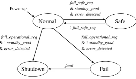
Fig. 5 shows the state diagram of the safety mode of the system. In this diagram, for simplicity, the case of the installation of a new unit is not considered. When
standby good is active, the standby unit is normally
operating. fail safe req andfail operational req are gen-erated from the mode list. When fail safe reqis active, it indicates that the robot is performing a safety-related task.
When fail operational req is active, it indicates that the
robot will continue to act after all the units have become faulty. In the normal state, the robot has multiple normal units, or it has one normal unit iffail safe reqis inactive. In the safe state, the robot has one normal unit and acts in the fail-safe mode. In the fail state, the robot does not have any normal units and acts in the fail-operational mode. If the system frequently undergoes failure, fatal becomes active and the system transitions to the shutdown state. In the shutdown state, the robot is powered off in a safe posture.
IV. IMPLEMENTATION OFTASK-BASEDDYNAMIC FAULTTOLERANCE
A. Safety Operation upon Computer Failure
We consider the safety operation of humanoid robots in a case where the computer unit fails. Reference [19] is
a patent describing a safety operation in mobile robots based on a distributed control system, and it focuses on biped-walking humanoid robots. Each of the local controllers that are installed in the joints of a robot is equipped with a ROM that stores predetermined motion data to control the servo independently from the central controller when a critical error occurs between the local controller and the central controller. For biped-walking robots, falling down is a critical problem with regard to safety. If the central controller fails while the robot is walking, each local controller leads the robot to a safety position according to the motion data stored in the ROM. The safety position means a position that does not cause the robot to injure humans and the environment. This approach will function safely when the robot is sim-ply walking. However, humanoid robots have to realize various movements, and their motion patterns are un-countable. Moreover, the appropriate behaviors and safety positions in the case of emergency shutdown are different for different robot actions and surrounding environments. A safety position under one set of conditions could be hazardous under other conditions. Thus, it is impossible to predetermine the motion patterns that ensure safety under all conditions. A solution that guarantees the safety of humanoid robots with such characteristics is to design the robot to always compute the motions leading to a safety position in case of failure of the computer unit. We incorporate this safety approach in the task-based dynamic fault tolerance by using the redundancy of the computer unit.
B. Implementation
From the considerations described in Section III, the redundant computer system presented here is composed of two units based on standby sparing, each of which implements a single CPU set. Fig. 6 shows a block diagram of the duplex system. The CPU accesses the boot ROM at power-up. The boot ROM stores the data required to start the system and stabilize the robot. The local memory stores motion data that contains the succeeding motions from the present time and the motions to lead the robotic system to a safe condition. The redundancy controller is a key component in the realization of a dependable robot; it has the following main functions:
• Communication between the units • Power management
• CPU supervisor
• Arbitration of the local bus • Safety failover
Data
storage BootROM CPU MediaInterface
Mechanical units
Local Memory Redundancy
Controller
Mechanical Interface
Isolator Vision
and audio sensors
Sensory Processor
Redundancy Controller Local
Memory Mechanical
Interface
CPU BootROM
Media Interface
Bus Bridge Main Memory Sensory
Processor MemoryController
Isolator
Main Memory Memory
Controller
Operational unit Standby unit
Data
standby_good failover
Safety failover subsystem Safety failover subsystem
standby_mode
DC/DC remote on/off
Bus Bridge
DC/DC
remote on/off
motion data
Local bus Local bus
Figure 6. Block diagram of the duplex computer system. The CPU block may consist of multiple processors.
When standby mode is low, the standby unit is set
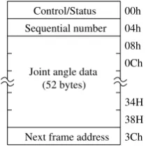
to the cold standby state. The redundancy controller in the standby unit disables the output of the DC/DC converter to stop the supply of power to the CPU set, main memory, and other devices in the shaded region. The redundancy controller and the local memory are always active, while the mechanical interface device enters a low-power mode. The CPU in the operational unit performs motion planning and writes the motion data to the local memories in both the units (dashed line in Fig. 6). The memory area for the motion data has been partitioned into segments referred to as motion data frames, each of which stores joint angle data. The top address of the motion data frame is aligned on a 64-byte boundary. The frame format is shown in Fig. 7. The motion of the robot is represented by a time series of joint angles. Letζ(t)be the joint angle data at timet, wheretis the present time. The motion data consists ofζ(t),ζ(t+1),· · ·, andζ(t+k). Each motion data frame contains a sequence number and the top address of the motion data frame that contains the next joint angle data; this information is utilized by the redundancy controller to combine the time-series joint angle data. The redundancy controller generates 1-ms interruptions to update the joint angles at intervals of 1 ms each. On receiving the 1-ms interruption from the redundancy controller, the CPU writes the value of the top address of the motion data frame that contains ζ(t+ 1) to the motion data address registers (MDARs) of both
00h 04h 08h 0Ch
3Ch 38H 34H Control/Status Sequential number
Next frame address Joint angle data
(52 bytes)
Figure 7. Format of the motion data frame.
the redundancy controllers. The redundancy controller of the operational unit refers to its MDAR and transfers
ζ(t+1)from the local memory to the mechanical interface device. Synchronizing both the redundancy controllers is the responsibility of the CPU. The interruptions of 1 ms are generated when the value of the 1-ms counter returns to zero. After receiving a 1-ms interruption from the redundancy controller of the operational unit, the CPU accesses the redundancy controller of the standby unit and reads the counter value. When the value is above a thresholdTlor below another thresholdTh(Tl< Th), the CPU resets the 1-ms counter of the redundancy controller of the standby unit.
t t+1 ... t+i ... t+j ... t+k Time
Motion data ζ (t)ζ (t+1) ζ (t+i) ζ (t+j) ζ (t+k) Present position Safety position
... ... ...
Occurance of failure
Figure 8. Illustration of a robot motion upon computer failure.
behaviors during failover, a safety failover subsystem is implemented in the redundancy controller. The redun-dancy controller has a watchdog function to check the condition of the CPU. The controller sends the 1-ms inter-ruption to the CPU and checks whether the CPU correctly accesses the MDAR in the controller within 1 ms. When this access is not detected,error detectedshown in Figs. 4 and 5 is active; the redundancy controller drives failover
if standby goodis active. The controller isolates the unit
from the robotic system by enabling the isolator. The operational unit enters the faulty state and is disabled.
Whenfailoveris driven, the redundancy controller of the
standby unit enables the DC/DC converter and activates the unit. Simultaneously, the safety failover subsystem in-side successively transfers motion data to the mechanical interface unit every 1 ms. Fig. 8 depicts an example of a motion that is performed after computer failure. In the figure, when a robot is walking, failover occurs at time t. The robot is walking at time t+i. It continues walking in the time interval betweent+iandt+j during which it starts to move in a safety position; it finally attains the safety position at timet+k. If the movement time during failover is limited to 5 s, the minimum memory required for motion data is 320 Kbytes. The safety approach based on the computation of redundant motion data enables the utilization of cold standby in the computer unit of humanoid robots; this approach prevents not only the falling down of the robot but also any hazardous behaviors caused by the failure of the computer unit.
When standby mode becomes high, the standby unit
is set to the hot standby state, and the standby unit is synchronized with the operational unit. Data equalization of the two units is performed through a bus between the memory controllers. Since the redundancy controller checks the condition of the CPU every 1 ms, the maxi-mum failover time in the hot standby state is 2 ms.
When the standby unit is faulty, i.e., standby good is inactive, the system will shut down or reboot with the next failure. In this case, while holding the CPU reset active, the redundancy controller of the operational unit transfers motion data from the local memory to the mechanical interface device and moves the robot to a safety position. If the safety mode of the system is fail operational, the CPU reset is released by the redundancy controller after the robot attains the safety position.
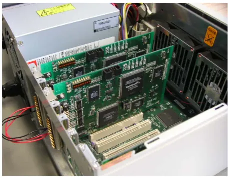
Figure 9. Duplex evaluation boards.
In terms of power consumption and size, this duplex system represents the minimum structure capable ensur-ing the availability and safety of humanoid robots. The redundancy controller and local memory are components that are added in order to realize the duplex system. If the power consumption of these components is sufficiently small, the power consumption of this duplex system can be equivalent to that of the single system when the standby unit is in the cold standby state.
V. DEVELOPMENT OF THEREDUNDANCY CONTROLLER
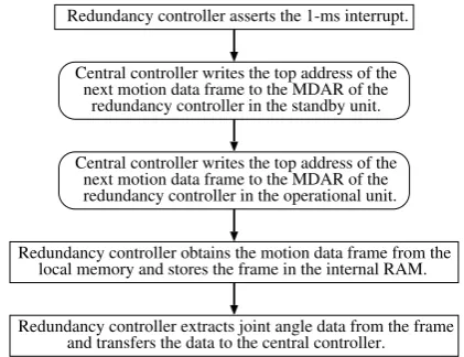
Redundancy controller asserts the 1-ms interrupt.
redundancy controller in the standby unit.
local memory and stores the frame in the internal RAM.
Redundancy controller extracts joint angle data from the frame next motion data frame to the MDAR of the Central controller writes the top address of the
redundancy controller in the operational unit. next motion data frame to the MDAR of the Central controller writes the top address of the
Redundancy controller obtains the motion data frame from the
and transfers the data to the central controller.
Figure 10. Operations of the redundancy controller for motion data.
2880. We implemented the safety failover subsystem and other fundamental functions of the redundancy controller in this device. The PCI function was designed by the author without using a commercial PCI IP core; its master and target functions consist of circuits required to perform only basic transactions. As a result, the design of the redundancy controller required 33% of the available logic elements of the device. The amount of power consumption for the FPGA can be calculated by referring to the application note of Altera [20]. The power consumption of the redundancy controller was approximately 0.24 W. In comparison to the power dissipation in high-performance CPUs, the power consumption of the redundancy con-troller is at a negligible level.
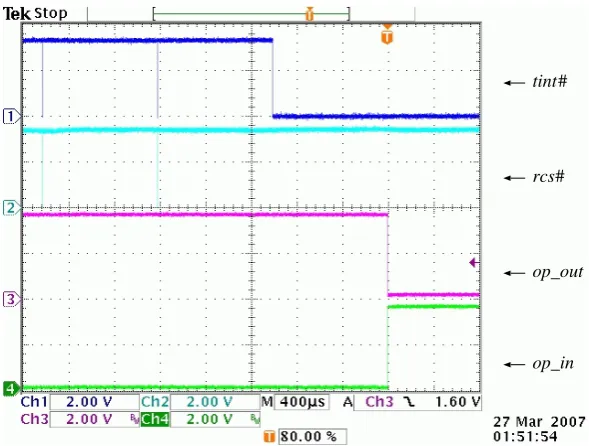
In this duplex system, the operational unit is automat-ically determined at up. Immediately after power-up, the central controller reads the status register of the redundancy controller to detect whether the unit is operational or in standby. Fig. 10 shows the operations of the redundancy controller for motion data. On receiving the 1-ms interrupt, the central controller requests the bus by asserting its request signal in order to access the MDAR of the redundancy controller in the standby unit. The time required from the assertion of the request signal to the completion of the transfer of 52-byte joint angle data is 3.6µs on the condition that all the latencies on the local bus and the PCI bus are minimum. We tentatively generated a fault in the central controller of the operational unit. Fig. 11 shows the waveforms triggered at the occurrence of failover. The # symbol at the end of a signal name indicates that the signal is active low. tint# is the 1-ms interrupt signal to the central controller. rcs# is the select signal to the redundancy controller and is driven by the central controller. op out is a status signal that indicates that the board is in the operational state, and
op in is an input signal that is equivalent to the op out
signal of the other board. After the failure occurred,tint# remained low because the interrupt status was not cleared by the central controller. Since tint# was not cleared for 1 ms, failover was performed.
VI. CONCLUSION
Future humanoid robots will be involved in various tasks, including safety-related tasks. In this scenario, the requirement for the dependability of the humanoid robot will dynamically change according to the importance of the tasks. This paper demonstrated that humanoid robots require a new type of fault tolerance and presented a duplex computer system that switches between hot standby and cold standby according to each individual task. Among real-world redundant computer systems that use standby sparing, there exist very few systems that switch dynamically between hot standby and cold standby during operation; this is because dynamic switching of the standby mode has not been an application requirement thus far. Humanoid robots could be the typical application that requires such dynamic fault tolerance schemes. We indicated that a safety issue arises in humanoid robots when cold standby is used for their standby computer unit. Since failover during cold standby requires a long time, the robot remains inactive in the meanwhile and therefore poses a hazard. In a human environment, the emergency stopping of a mobile robot does not necessarily guarantee the safety of the robot. This paper also presented a safety failover subsystem to resolve this problem. We note that the proposed fault tolerance scheme is effective not only for humanoid robots but any mobile robot that must act autonomously in a human environment.
REFERENCES
[1] A. Avizienis, J. -C. Laprie, B. Randell, and C. Landwehr, “Basic concepts and taxonomy of dependable and secure
computing,”IEEE Trans. Dependable and Secure
Comput-ing, Vol. 1, No. 1, pp. 11–33, Jan. 2004.
[2] K. Kaneko, F. Kanehiro, S. Kajita, M. Morisawa,
K. Fujiwara, K. Harada, and H. Hirukawa, “Motion
suspension system for humanoids in case of emergency; real-time motion generation and judgment to suspend
humanoid,” Proc. 2006 IEEE/RSJ International
Conference on Intelligent Robots and Systems, Beijing, China, Oct. 2006, pp. 5496–5503.
[3] T. Takubo, T. Tanaka, K. Inoue, and T. Arai, “Emergent walking stop using 3-D ZMP modification criteria map for
humanoid robot,”Proc. 2007 IEEE International
Confer-ence on Robotics and Automation, Roma, Italy, Apr. 2007, pp. 2676–2681.
[4] K. Fujiwara, S. Kajita, K. Harada, K. Kaneko,
M. Morisawa, F. Kanehiro, S. Nakaoka, and H. Hirukawa, “Towards an optimal falling motion for a humanoid
robot,”Proc. 2006 IEEE-RAS International Conference on
Humanoid Robots, Genova, Italy, Dec. 2006, pp. 524–529.
[5] K. Kaneko, F. Kanehiro, S. Kajita, H. Hirukawa,
T. Kawasaki, M. Hirata, K. Akachi, and T. Isozumi,
“Humanoid robot HRP-2,”Proc. 2004 IEEE International
Conference on Robotics and Automation, New Orleans, Louisiana, Apr. 2004, pp. 1083–1090.
[6] M. Shiomi, T. Kanda, N. Miralles, T. Miyashita, I. Fasel, J. Movellan, and H. Ishiguro, “Face-to-face interactive
hu-manoid robot,” Proc. 2004 IEEE/RSJ International
tint
rcs
op_in op_out
# #
Figure 11. Waveforms at the occurrence of failure.
[7] M. Bennewitz, F. Faber, D. Joho, M. Schreiber, and
S. Behnke, “Integrating vision and speech for conversations
with multiple persons,”Proc. 2005 IEEE/RSJ International
Conference on Intelligent Robots and Systems, Edmonton, Canada, Aug. 2005, pp. 2523–2528.
[8] S. Yamamoto, K. Nakadai, J. -M. Valin, J. Rouat,
F. Michaud, K. Komatani, T. Ogata, and H. Okuno,
“Making a robot recognize three simultaneous sentences
in real-time,” Proc. 2005 IEEE/RSJ International
Conference on Intelligent Robots and Systems, Edmonton, Canada, Aug. 2005, pp. 4040–4045.
[9] R. Bischoff and V. Graefe, “Design principles for
depend-able robotic assistants,”International Journal of Humanoid
Robotics, Vol. 1, No. 1, pp. 95–125, Mar. 2004.
[10] K. Suzuki and S. Hashimoto, “A multi-layered hierarchical
architecture for a humanoid robot,”Proc. 7th International
Conference on Knowledge-Based Intelligent Information and Engineering Systems (Lecture Notes in Artificial Intel-ligence 2774, Springer), Oxford, UK, Sep. 2003, pp. 592– 599.
[11] T. Asfour, K. Regenstein, P. Azad, J. Schroder,
A. Bierbaum, N. Vahrenkamp, and R. Dillmann, “ARMAR-III: An integrated humanoid platform for sensory-motor
control,” Proc. 2006 IEEE/RAS International Conference
on Humanoid Robots, Genova, Italy, Dec. 2006, pp. 169– 175.
[12] D. Kaynov and C. Balaguer, “Industrial automation based approach to design control system of the humanoid robot,”
Proc. 2007 International Symposium on Industrial Elec-tronics (ISIE 2007), Vigo, Spain, Jun. 2007, pp. 2179– 2184.
[13] F. Kanehiro, Y. Ishikawa, H. Saito, K. Akachi,
G. Miyamori, T. Isozumi, K. Kaneko, and H. Hirukawa, “Distributed control system of humanoid robots based on
real-time Ethernet,” Proc. 2006 International Conference
on Intelligent Robots and Systems (IROS 2006), Beijing, China, Oct. 2006, pp. 2471–2477.
[14] V. P. Nelson, “Fault-tolerant computing: fundamental
con-cepts,”IEEE Computer, Vol. 23, No. 7, Jul. 1990, pp. 19–
25.
[15] O. Rooks, M. Armbruster, A. Sulzmann, G. Spiegelberg, and U. Kiencke, “Duo duplex drive-by-wire computer
system,” Reliability Engineering and System Safety,
Vol. 89, No. 1, pp. 71–80, Jul. 2005.
[16] T. Matsui, H. Hirukawa, Y. Ishikawa, N. Yamasaki,
S. Kagami, F. Kanehiro, H. Saito, and T. Inamura,
“Distributed real-time processing for humanoid robots,”
Proc. 11th IEEE International Conference on Embedded and Real-Time Computing Systems and Applications, Hong Kong, China, Aug. 2005, pp. 205–210.
[17] S. Brown, “Overview of IEC 61508: Design of electri-cal/electronic/programmable electronic safety-related
sys-tems,” Computing and Control Engineering Journal,
Vol. 11, No. 1, pp. 6–12, Jan. 2000.
[18] J. F. Hanaway and R. W. Moorehead, “NASA SP-504:
Space shuttle avionics system,” NASA Office of Logic
Design, 1989,
URL:
http://klabs.org/DEI/Processor/shuttle/sp-504/sp-504.htm.
[19] Y. Suzuki, “A control device for mobile robots,” Japanese patent, Publication Number 2001–239480, Dec. 2000. (in Japanese)
[20] “Evaluating Power for Altera Devices,” Application Note: A-AN-074-03.1, Altera Corporation, San Jose, CA, Jul. 2001.
Masayuki Murakamireceived the B.Eng. and M.Eng. degrees in electronics and information engineering from the University of Electro-Communications (UEC), Tokyo, Japan, in 1994 and 1996, respectively, and the Ph.D. degree in systems engineering from UEC in 2008.