BROOKFIELD DV-II+ PROGRAMMABLE VISCOMETER Operating Instructions Manual No. M/97-164-D1000 SPECIALISTS IN THE MEASUREMENT AND CONTROL OF VISCOSITY
TABLE OF CONTENTS I. INTRODUCTION ... 3 I.1 Components ... 4 I.2 Utilities ... 4 I.3 Specifications ... 4 I.4 Installation ... 5
I.5 Key Functions ... 6
II. GETTING STARTED ... 8
II.1 Autozero ... 8
II.2 Spindle Selection ... 9
II.3 Speed Selection, Setting, Running ... 10
II.4 Display Selection ... 11
II.5 Autorange ... 12
II.6 Out of Range ... 13
II.7 Temperature Display ... 14
II.8 Printing ... 14
II.9 Making Viscosity Measurements ... 15
II.10 Time Modes for Viscosity Measurement ... 16
III. OPTIONS ... 17
III.1 Introduction to OPTIONS ... 17
III.2 Setup ... 19
III.2.1 Temperature Display ... 20
III.2.2 Units of Measurement ... 20
III.2.3 Motor Speed Set Selection ... 21
III.2.4 Printer Output Port ... 22
III.2.5 Data Averaging ... 22
III.3 Time Modes ... 23
III.3.1 Time to Stop ... 24
III.3.2 Time to Torque ... 26
III.3.3 Print Time Interval ... 28
III.3.4 PC Program (On/Off) ... 29
III.3.5 Download a Program ... 29
III.3.6 Run a Program ... 30
IV. DVLOADER SOFTWARE ... 33
IV.1 B.E.V.I.S. Overview ... 33
IV.2 Description of B.E.V.I.S. Commands ... 34
IV.3 Creating a B.E.V.I.S. Program ... 35
IV.4 Downloading a B.E.V.I.S. Program ... 37
IV. 5 Example Programs ... 38
Appendix A - Cone/Plate Viscometer Set-Up ... 40
Appendix B - Viscosity Ranges ... 44
Appendix C - Variables in Viscosity Measurements ... 47
Appendix D - Spindle and Model Codes ... 49
Appendix E - Calibration Procedures ... 52
Appendix F - Speed Sets ... 59
Appendix G - Communications ... 60
Appendix H - Laboratory Stands... 63
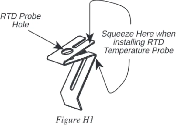
Appendix I - DVE-50 Probe Clip ... 67
Appendix J - Fault Diagnosis and Troubleshooting ... 68
I. INTRODUCTION
The Brookfield Programmable DV-II+ Viscometer measures fluid viscosity at given shear rates. Viscosity is a measure of a fluid’s resistance to flow. You will find a detailed description of the mathematics of viscosity in the Brookfield publication ”More Solutions to Sticky Problems” a copy of which was included with your DV-II+.
The principal of operation of the DV-II+ is to drive a spindle (which is immersed in the test fluid) through a calibrated spring. The viscous drag of the fluid against the spindle is measured by the spring deflection. Spring deflection is measured with a rotary transducer. The measure-ment range of a DV-II+ (in centipoise or milliPascal seconds) is determined by the rotational speed of the spindle, the size and shape of the spindle, the container the spindle is rotating in, and the full scale torque of the calibrated spring.
There are four basic spring torque series offered by Brookfield: Spring Torque
Model dyne-cm milli Newton - m
LVDV-II+ 673.7 0.0673
RVDV-II+ 7,187.0 0.7187
HADV-II+ 14,374.0 1.4374
HBDV-II+ 57,496.0 5.7496
The higher the torque calibration, the higher the measurement range. The measurement range for each torque calibration may be found in Appendix B.
All units of measurement are displayed according to either the CGS system or the SI system.
1. Viscosity appears in units of centipoise (shown as “cP”) or milliPascal-seconds (shown as “mPa•s”) on the DV-II+ Viscometer display.
2. Shear Stress appears in units of dynes/square centimeter (“D/cm2”) or Newtons/square
meter (“N/m2”).
3. Shear Rate appears in units of reciprocal seconds (“1/SEC”).
4. Torque appears in units of dyne-centimeters or Newton-meters (shown as percent “%” in both cases) on the DV-II+ Viscometer display.
Note: To change CGS to SI units on the display - see Section III.2.2.
The equivalent units of measurement in the SI system are calculated using the following conversions:
SI CGS
Viscosity: 1 mPa•s = 1 cP
Shear Stress: 1 Newton/m2 = 10 dyne/cm2
Torque: 1 Newton-m = 107 dyne-cm
References to viscosity throughout this manual are done in CGS units. The DV-II+ Viscometer provides equivalent information in SI units.
I.1 Components
Component Part Number Quantity
DV-II+ Viscometer varies 1
Model S Laboratory Stand MODEL S 1
Spindle Set with Case varies 1
LVDV-II+ set of four spindles or (SSL) 1
RVDV-II+ set of seven spindles or (SSR) 1
HA/HBDV-II+ set of seven spindles (SSH) 1
For Cone/Plate versions: a spindle wrench, one cone spindle and sample cup, Part No. CPE-44Y replace the spindle set.
Power Cord 1
DVP-65 for 115 or DVP-66 for 230
RTD Temperature Probe DVP-94Y 1
Guard Leg: 1
LVDV-II+ B-20Y
RVDV-II+ B-21Y
Carrying Case DVE-7Y 1
DVLOADER Software Disk (3-1/2") DVLOADER 1
Interconnecting Cable DVP-80Y 1
Operating Manual M/97-164 1
Please check to be sure that you have received all components, and that there is no damage. If you are missing any parts, please notify Brookfield Engineering or your local Brookfield agent immediately. Any shipping damage must be reported to the carrier.
I.2 Utilities
Input Voltage: 115 VAC or 230 VAC Input Frequency: 50/60 Hz
Power Consumption: Less than 20 WATTS Power Cord Color Code:
United States Outside United States
Hot (live) Black Brown
Neutral White Blue
Ground (earth) Green Green/Yellow
I.3 Specifications
Speeds: Interleaved: LV/RV (18 speeds) Sequential: LV/RV (18 speeds) Custom: 54 speeds, user selectable
Weight: Gross Weight 23 lbs. 10.5 kg.
Net Weight 20 lbs. 9 kg.
Carton Volume 1.65 cu. ft. 0.05 m3 Temperature sensing range: -100˚C to 300˚C (-148˚F to 572˚F) Analog Torque Output: 0 - 1 Volt DC (0 - 100% Torque) Analog Temperature Output: 0 - 4 Volts DC (10mv / ˚C)
RS232 Compatible Serial Port for use with an attached printer or PC. Centronics Compatible Parallel Port for use with an attached printer. Viscosity Accuracy: ±1.0% of full scale range
Viscosity Repeatability: ±0.2%
Temperature Accuracy: ±1°C : -100°C to +149°C
±2°C : +150°C to +300°C
Electrical Certifications: CUL (expected by April 2000), CE I.4 Installation
1) Assemble the Model S Laboratory Stand (refer to assembly instructions in Appendix H). 2) Connect the RTD probe to the socket on the rear panel of the DV-II+.
3) The Viscometer must be leveled. The level is adjusted using the two leveling screws on the base. Adjust so that the bubble level on top of the DV-II+ is centered within the circle.
Note: Check level periodically during use.
4) Remove the white shipping cap which secures lower coupling nut on Viscometer to pivot cup.
5) Make sure that the AC power switch at the rear of the DV-II+ is in the OFF position. Connect the power cord to the socket on the back panel of the instrument and plug it into the appropriate AC line. The AC input voltage and frequency must be within the appropriate range as shown on the name plate of the Viscometer.
Note: The DV-II+ must be earth grounded to ensure against electronic failure!!
6) Turn the power switch to the ON position and allow to warm up for 10 minutes before performing autozero.
7) For Cone/Plate models, refer to Appendix A.
8) If appropriate, connect interconnecting cable to serial port for connection of DV-II+ to PC or printer.
9) If appropriate, connect interconnecting cable to parallel port for connection of DV-II+ to printer.
I.5 Key Functions
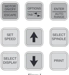
Figure 1 shows the control keys on the face of the DV-II+ Viscometer. The following describes the function of each key.
UP ARROW
This key is used to scroll UP (in an increasing value direction) through the available speed, spindle and Option menu tables.
DOWN ARROW
This key is used to scroll DOWN (in a decreas-ing value direction) through the available speed, spindle and option menu tables.
MOTOR ON/OFF
ESCAPE MOTOR ON/OFF/ESCAPE
Turns the motor ON or OFF. ESCAPE exits the Options menu.
SET
SPEED SET SPEED
Causes the DV-II+ to begin running at the currently selected speed. This function works only when the motor is ON. Also used to select custom speeds when in the Custom Speed option.
SELECT
DISPLAY SELECT DISPLAY
Selects the data parameter to be displayed:
cP Viscosity (cP or mPa.s)
SS Shear Stress (dynes/cm2 or Newtons/m2) SR Shear Rate (1/sec)
AUTO RANGE ENTER
ENTER/AUTO RANGE
ENTER: Used to execute the currently flashing option.
AUTO RANGE: Presents the maximum (100% torque) viscosity attainable using the selected spindle at the current viscometer spindle speed.
SELECT SPINDLE SELECT
SPINDLE SELECT SPINDLE
Initiates spindle selection on the first press and then selects the currently scrolled-to spindle when pressed a second time.
PRINT PRINT
Selects printing and non-printing modes when a printer is attached.
Figure 1 SET SPEED SELECT SPINDLE SELECT SPINDLE PRINT SELECT DISPLAY MOTOR ON/OFF ESCAPE AUTO RANGE ENTER TAB OPTIONS
TAB OPTIONS
OPTIONS/TAB
OPTIONS: Presents the Options menu, flashing the last escaped option.
TAB: Toggles between selectable items when indicated, as shown in Figure 2.
L°F(FAHRENHEIT) CGS UNITS
Note: Symbol indicating the OPTIONS/TAB key
Figure 2
Note: Inverted text (black background with white lettering) indicates that the information is flashing on the viscometer display.
II. GETTING STARTED
II.1 AutozeroBefore readings may be taken, the Viscometer must be Autozeroed. This action is performed each time the power switch is turned on. The display window on the Viscometer will guide you through the procedure as follows:
Turn the power switch (located on the rear panel) to the ON position. This will result in the screen display shown in Figure 3. The viscosity measurement range is indicated by the information in the lower left, in this case RV. For most DV-II+ Viscometers, this information will be either “LV” or “RV”.
BROOKFIELD DV-2+ RV VISCOMETER
Figure 3
After a few seconds, the following screen appears:
BROOKFIELD DV-2+ VERSION: 5.0
Figure 4
No key press is required at this point. After a short time, the display will clear and the following will be displayed:
REMOVE SPINDLE PRESS ANY KEY
Figure 5
After removing the spindle and pressing any key, the DV-II
+
begins its Autozero. The screen will flash "Autozeroing."After approximately 15 seconds, the display shows the screen in Figure 6: REPLACE SPINDLE
PRESS ANY KEY
Figure 6
Pressing any key at this point results in the display of the DV-II
+
default screen:CP 0.0 20.1C OFFRPM % 0.0
Figure 7
The display will vary depending upon the selection of temperature (°F or °C) and units of viscosity (cP or mPa•s).
II.2 SELECT SPINDLE SELECT
SPINDLE Spindle Selection
LVDV-II+ Viscometers are provided with a set of four spindles and a narrow guardleg; RVDV-II+ Viscometers come with a set of seven spindles and a wider guardleg; HADV-II+ and HBDV-II+ Viscometers come with a set of seven spindles and no guardleg. (See Appendix E for more information on the guardleg.)
The spindles are attached to the viscometer by screwing them onto the lower shaft. Note that the spindles have a left-hand thread. The lower shaft should be secured and slightly lifted with one hand while screwing the spindle to the left. The face of the spindle nut and the matching surface on the lower shaft should be smooth and clean to prevent eccentric rotation of the spindle. Spindles can be identified by the number on the side of the spindle coupling nut.
The DV-II+ must have a Spindle Entry Code number to calculate Viscosity, Shear Rate and Shear Stress values. The DV-II+ memory contains parameters for all standard Brookfield spindles including custom spindles and the two digit entry code for each spindle (the complete list of entry codes may be found in Appendix D).
Note: The DV-II+ will remember the Spindle Entry Code which was in use when the power was turned off.
Pressing the SELECT SPINDLE key will display the current selected spindle code instead of temperature and cause the character S to begin to blink . It will blink for about three seconds. If the UP or DOWNARROW keys are pressed (while S is blinking) the two character spindle value to the right of the S character will begin to change (in either an increasing or decreasing direction depending upon which ARROW key is pressed) for each press of the key. If the ARROW key is pressed and held, the display will scroll through the spindle codes for as long as the ARROW key is depressed. When it reaches the last item in the list (either at the top or bottom of the list) the spindle code displayed will “roll-over” to either the first or last spindle code and the scroll action will continue.
When the desired spindle code is displayed, release the ARROW key to halt further scrolling. Press the SELECT SPINDLE key once again. This will cause the S character to cease blinking and the new spindle code will be accepted for use in viscometer calculations.
Note: You have approximately three seconds in which to press the SELECT SPINDLE key before the blinking stops. If you fail to press the SELECT SPINDLE key
before the blinking stops you will have to repeat the above steps and re-select
the desired spindle.
The DV-II+ will begin to calculate using the new spindle parameters as soon as the SELECT SPINDLE key is pressed the second time.
Note: The number 99 spindle is for use with special spindles when using Brook-field’s WINGATHER computer program. Refer to the WINGATHER operator manual for further information on using “99” spindles.
The DV-II+ may also be programmed at Brookfield Engineering for “special” user spindles. These “special” spindles will appear on the spindle scroll list starting with designation “AA” and continuing
II.3 SET
SPEED Speed Selection, Setting, Running
There are 54 speeds programmed into the DV-II+. These speeds correspond to the standard LVT, RVT, HAT, HBT, LVF and RVF dial models (18 possible speeds altogether) plus 36 additional speeds.
The DV-II+ comes with the Sequential Speed Set already selected (see Appendix F). The speed set will start at speed 0.0. It will then scroll up through the LV speeds, pass through speed 0.0 again, and then scroll up through the RV speeds, pass through speed 0.0 again and then repeat the above sequence.
The DV-II+ can also be configured by the operator to interleave the LV and RV speeds. See Section III.2.3 on Setup for a description of how to install the Interleave Speed Set.
A complete list of speed sets and custom speeds is included in Appendix F. The DV-II+ can be programmed to select up to 19 of the 54 speeds for use at any one time. Speed 0.0 is the 20th speed and is automatically included. See Section III. 2.3.2 on Setup for a description of how to install a Custom Speed Set.
To select a Viscometer speed first press either the UP or DOWN arrow keys which will cause the area to the right of RPM to display the currently selected speed. Figure 8 shows the DV-II+ is operating at 6.0 RPM, and the current selected speed is 6.0 RPM.
cP 123.4 20.1C 6.0RPM6.0 % 15.6
Figure 8
If the ARROW key is pressed just once and then released, the characters “RPM” will blink for three seconds, then will cease blinking resulting in no change to the speed entry.
Note: The speed selection process remembers the last value of scrolled-to speed so that the next time you initiate a speed change (by pressing an ARROW key), the DV-II+ will begin its scroll display from the last entered value.
The last-scrolled-to speed does not necessarily have to be the same as the speed at which the DV-II+ is currently running. The user may operate at a given speed and pre-set the DV-DV-II+ to the next desired speed before that speed will be used. For example, if the DV-II+ is currently running at 6.0 RPM and was previously scrolled to 12 RPM, a single press of either ARROW key would result in the Figure 9 screen display:
cP 123.4 20.1C 6.0RPM12 % 15.6
Figure 9
Pressing the SET SPEED key would cause the DV-II+ to begin running at 12 RPM.
If the user did not press the SET SPEED key, the DV-II
+ would continue to run at its current speed
of 6 RPM. In fact, you may scroll to a new speed (12 RPM in this example) and press the SET SPEED key at any future time (without further pressing an ARROW key) to immediately cause the DV-II+ to run at the new speed. Pressing the ARROW key at any time reminds the operator of what wasselected for the next speed.
If an ARROW key is pressed and held the DV-II+ will scroll up (or down) through the speed table. When it reaches the last speed in the list (either at the top or bottom of the list) the speed displayed will “roll-over” to either the first or last speed in the table and the scroll action will continue. When the required speed is displayed, release the ARROW key to halt further scrolling. You have approximately two seconds (before the blinking RPM stops) in which to press the SET SPEED key to immediately begin rotation at the new speed.
Pressing the MOTOR ON/OFF/ESCAPE key stops the Viscometer spindle rotation. Pressing this key sets the DV-II+ to 0.0 RPM and causes the screen display to change as shown in Figure 10:
cP 0.0 20.1C OFFRPM % 0.0
Figure 10
Pressing the MOTOR ON/OFF/ESCAPE key again immediately starts the DV-II+ running at the last
scrolled-to-speed. If you had been running at 12 RPM, pressed MOTOR ON/OFF/ESCAPE and then re-started the DV-II+ by pressing MOTOR ON/OFF/ESCAPE once again, you would again be running at 12 RPM. However, if while the motor was off you had scrolled to a new speed of 0.5 RPM, pressing the MOTOR ON/OFF/ESCAPE key would start the DV-II+ running at 0.5 RPM.
Note: During both spindle or speed selection and scrolling operations, the DV-II+ will continue to calculate and display Viscometer data as selected.
II.4 SELECT
DISPLAY Display Selection
Viscosity (displayed in units of cP or mPa•s), Shear Stress and Shear Rate are displayed on the left side of the top line. You may “step” through the three display options by pressing the SELECT DISPLAY key. For example, the DV-II+ is currently displaying Viscosity as shown in Figure 11:
cP 123e3 20.1C 6.0RPM % 15.6
Figure 11
If the viscosity value exceeds 99,999 scientific notation is used. In Figure 11, the viscosity value is 123,400 cP.
The first press of the SELECT DISPLAY key would display Shear Stress (SS) in Dynes/cm2 (or
Newtons/m2), see Figure 12:
SS 29.0 20.1C 6.0RPM % 15.6
SR 40.0 20.1C 6.0RPM % 15.6
Figure 13
One more press of the SELECT DISPLAY key would result in a return to the viscosity screen, as shown in Figure 11.
Notes: 1. You may step through the display at any time. This will not interrupt any Viscometer calculations that are in progress.
2. Display of shear rate and shear stress requires selection of appropriate spindles. Otherwise, values displayed will be zero (0).
Units of Measurement
The DV-II+ Viscometer can be configured using the SETUP option (Section III.2.2) to display/ print in either the CGS or SI system of units.
II.5 AUTO RANGE ENTER
Autorange
The ENTER/AUTO RANGE key functions as auto range and allows you to determine the maximum calculated viscosity (full scale reading) possible with the current spindle/speed setting only when in the default screen. Pressing the key at any time will cause the current viscosity display to change and show that maximum viscosity. The screen area displaying % (torque) will now display a flashing “%100.0” to indicate this special condition. This maximum viscosity and flashing %100.0 value will be displayed for as long as the ENTER/AUTO RANGE key is depressed. Figure 14 shows the AUTO RANGE function for the situation where the No. 1 LV spindle is rotating at 60 rpm. The full scale
range is 100.0 cP (or 100.0 mPa.s).
cP 100.0 S61 60 RPM % 100
Figure 14
Notes: 1. If the RPM is 0.0, the maximum viscosity displayed will be 0.0 cP (or 0.0 mPa.s).
2. While the Viscometer is in the Auto Range mode, any data sent to an attached printer or computer reflects the displayed values (i.e. Auto Range values).
II.6 Out of Range
The DV-II+ gives indications for out-of-range operation. When % (Torque) readings exceed 100% (over-range), the display changes to that shown in Figure 15; EEEE will also appear in the display for % and viscosity or shear stress:
cP EEEE 20.1C 10 RPM % EEEE
Figure 15
You must change either speed or spindle to correct this condition. If you operate at spindle speeds that produce % (Torque) below 10.0 %, the DV-II+ flashes the % (Torque), cP (Viscosity), SS (Shear Stress) and SR (Shear Rate) as shown in Figure 16:
cP 12.4 20.1C 10 RPM % 8.2
Figure 16
Negative % (Torque) will be displayed as shown in Figure 17: cP ---- 20.1C 10 RPM % -2.2
Figure 17
Figure 18 is an example of the printed output of each of the above conditions.
Normal Operation:
RPM=50 M=RV S=29 %=51.4 cP=10280 D/CM2=1285 1/SEC=12.3 T=20.1C Z00:30
Over-Range Operation (>100% torque) (see Fig. 15):
RPM=50 M=RV S=29 %=EEEE cP=EEEE D/CM2=EEEE 1/SEC=12.3 T=20.1C Z00:30
Under-Range Operation (<10% torque) (see Fig. 16):
?RPM=50 M=RV S=29 %=5.2 cP=1040 D/CM2=130 1/SEC=12.3 T=20.1C Z00:30
Negative Torque Operation (see Fig. 17):
RPM=50 M=RV S=29 %=-0.1 cP=---- D/CM2=---- 1/SEC=12.3 T=20.1C Z00:30
II.7 Temperature Display
The DV-II+ displays the temperature measured by its RTD temperature probe. Temperature may be displayed in either ˚C (Centigrade) or ˚F (Fahrenheit) units, depending upon selection from the Options menu. As received, the default temperature display will be in ˚C (Centigrade) units as shown in the Figure 19:
cP 123.4 20.1C 10 RPM % 19.7
Figure 19
If you turn on the DV-II+ with the temperature probe disconnected, or remove the temperature probe at any point after power-up, the display will indicate “- - - -C”. The four “dashes” indicate the absence of the probe. If you were displaying temperature in Fahrenheit units the C would be replaced by an
F. Accuracy of temperature measurement for the DV-II+ is shown in Table 1.
Table 1
Temperature Accuracies for Programmable DV-II+ Viscometer
Temperature Range Temperature Accuracy -100°C to +149°C ±1.0°C
+150°C to +300°C ±2.0°C
II.8 PRINT Printing
The DV-II+ will print data to an attached Serial (RS232) or Parallel (centronics) printer. The printer must be attached to the appropriate rear panel output connector. See Appendix G for configuration and connection requirements.
Data may be printed in two ways:
1. Pressing the PRINT key once (for less than three (3) seconds) will result in the printing of one standard print line.
2. If the PRINT key is pressed and held for more than three (3) seconds, the DV-II+ will then begin
continuous printer output at a print rate interval selected via the Options menu (see Section III.4).
The display will show a flashing P in front of the % sign. See Figure 20. cP 123.4 20.1C
10 RPM P% 19.7
Figure 20
To stop continuous printing, press the PRINT key for one (1) second. The flashing P will disappear on the viscometer display.
Figure 21
When printing via the parallel port, please note that if a printer is not attached to the viscometer, the following screen appears:
PRINTER ERROR CHECK CONNECTION
Figure 22
II.9 Making Viscosity Measurements
The following general procedure is used for making viscosity measurements. Brookfield recom-mends the use of a 600 ml Low Form Griffin beaker when using LV/RV/HA/HB spindles. 1. Mount the guardleg on the DV-II+ Viscometer (LV and RV series).
2. Insert and center spindle in the test material until the fluid's level is at the immersion groove on the spindle's shaft. With a disc-type spindle, it is necessary to tilt the spindle slightly while immersing to avoid trapping air bubbles on its surface. Attach the spindle to the lower shaft of the viscometer. Lift the shaft slightly, holding it firmly with one hand while screwing the spindle on with the other (note left-hand thread). Avoid putting side thrust on the shaft. Verify the proper spindle immersion depth and that the viscometer is level.
3. The process of selecting a spindle and speed for an unknown fluid is normally trial and error. An
appropriate selection will result in measurements made between 10-100 on the instrument % torque scale. Two general rules will help in the trial and error process.
1) Viscosity range is inversely proportional to the size of the spindle. 2) Viscosity range is inversely proportional to the rotational speed.
To measure high viscosity, choose a small spindle and/or a slow speed. If the chosen spindle/ speed results in a reading above 100%, then reduce the speed or choose a smaller spindle.
For the case of CGS units with non-exponential results:
and CGS units with exponential results.
Similarly, for SI units with non-exponential results.
and SI units with exponential results.
M = Torque T = Temperature Z = Time
1 10 20 30 40 50 60 70 80
RPM=XXX M=XXXXX S=XX %=XXX.X cP=XXXXX D/CM2=XXXXX 1/SEC=XXXXX T=XX.XC ZXX=XX
RPM=XXX M=XXXXX S=XX %=XXX.X cP=XXXeX D/CM2=XXXeX 1/SEC=XXXXX T=XX.XC ZXX=XX
1 10 20 30 40 50 60 70 80
RPM=XXX M=XXXXX S=XX %=XXX.X mPas=XXXXX N/M2=XXXXX 1/SEC=XXXXX T=XX.XC ZXX=XX
1 10 20 30 40 50 60 70 80
1 10 20 30 40 50 60 70 80
Non-Newtonian fluid behavior can result in the measured viscosity changing if the spindle and/ or speed is changed. See our publication, “More Solutions to Sticky Problems,” for more detail. Allow time for the indicated reading to stabilize. The time required for stabilization will depend on the speed at which the Viscometer is running and the characteristics of the sample fluid. For maximum accuracy, readings below 10% should be avoided.
4. Press the MOTOR ON/OFF/ESCAPE key and turn the motor “OFF” when changing a spindle or changing samples. Remove spindle before cleaning.
5. Interpretation of results and the instrument's use with non-Newtonian and thixotropic materials is discussed in the booklet, "More Solutions to Sticky Problems", and in Appendix C, Variables in Viscosity Measurements.
II.10 Time Modes for Viscosity Measurement
The Time Modes allow the viscometer user to implement the unattended Time to Stop and Time to Torque capabilities of the DV-II+ Viscometer. These features will allow the user to set up the viscometer (i.e. select spindle and speed) and then record readings for a fixed period of time (Time to Stop) or until a set torque value is attained (Time to Torque). When timing begins, a message will be displayed showing time remaining (or time elapsed) and the appropriate display item (viscosity or torque) will be updated continuously during the event. Upon completion, the viscometer will stop and display a screen stating that the test is complete and will also display the final recorded value for the viscosity in the first case, or the time in minutes and seconds to reach the torque limit in the second case. Pressing the UP or DOWN ARROW keys will allow additional viscometer data to be examined. Pressing any other key (except the PRINT or ENTER/AUTORANGE key) will bring the user back to the default (normal) viscometer display with the motor OFF. Refer to the Time Modes in Section III.3.
III.
OPTIONS
III.1 TABOPTIONS
Introduction to OPTIONS
The OPTIONS/TAB key provides access to the configuration (Setup) of the DV-II+ Viscometer as
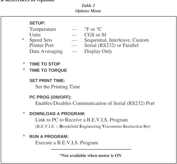
well as special functions that can enhance the user's ability to make viscosity measurements. The Options menu, shown in Table 1, gives a complete picture of the various configuration choices and special functions.
Quick References to Options
Table 2 Options Menu
SETUP:
Temperature — °F or °C
Units — CGS or SI
* Speed Sets — Sequential, Interleave, Custom Printer Port — Serial (RS232) or Parallel Data Averaging — Display Only
* TIME TO STOP * TIME TO TORQUE
SET PRINT TIME:
Set the Printing Time PC PROG (ON/OFF):
Enables/Disables Communication of Serial (RS232) Port * DOWNLOAD A PROGRAM:
Link to PC to Receive a B.E.V.I.S. Program
(B.E.V.I.S. = Brookfield Engineering Viscometer Instruction Set) * RUN A PROGRAM:
Execute a B.E.V.I.S. Program
*Not available when motor is ON
Pressing OPTIONS/TAB places you into the Options menu at the last option selected. The following keys are active and perform as follows:
UP ARROW - Scrolls up through menu or selects new value from list.
TAB OPTIONS
OPTIONS/TAB - Toggles between options.
AUTO RANGE ENTER
ENTER/AUTORANGE - Accepts the currently flashing option and moves user to next level (if applicable) of the selected option.
MOTOR ON/OFF
ESCAPE MOTOR ON/OFF/ESCAPE - Cancels current operation and backs user out one menu level. Repeated pressing will back the user out to the default screen. While in the Options menu, the MOTOR ON/OFF/ESCAPE key does not cause the viscometer motor to turn on or off! The Options menu screens will appear as shown in Figure 23 if you cycle through the possible options using the UP/DOWN arrows.
TIME TO TORQUE SET PRINT TIME
PC PROG OFF DOWNLOAD A PROG DOWNLOAD A PROG RUN A PROG SETUP TIME TO TORQUE
SET PRINT TIME PC PROG OFF
SETUP
TIME TO STOP LTIME TO STOP SET PRINT TIME SET PRINT TIME PC PROG ON LPC PROG ON DOWNLOAD A PROG
OR
OR
OR
OR
Figure 23On entry to the Options menu, the following rules regarding current viscometer operation are in force: 1. Printer output will be suppressed when in the Custom Speed option, the Time to
Torque and Time to Stop options, the Download A Program and Run A Program options. It will be continued when any other option is selected.
2. If the motor is ON when the user enters the Options menu, choices will be limited to: CGS/SI units (under SETUP), °F/°C units (under SETUP), PRINTING SELEC-TIONS and PC PROG.
Selecting an Option
The following is a quick reference for entering and using the OPTIONS menu:
Press TAB OPTIONS
To enter Options Menu
Press or To scroll to a specific option
For Options:
Press TAB OPTIONS
To toggle between the choices available for a specific option when indicated
Press AUTO RANGE ENTER
To select the flashing option
III.2 Setup
From the main Options screen, the user scrolls up or down until the following screen is displayed: SETUP
TIME TO TORQUE
Figure 24
A press of the ENTER/AUTORANGE key takes you into the Setup sub-menu (Figure 25). As in the main Options menu, you can scroll up or down through the various Setup options. In order to access all options, the motor must be turned off.
L°F(FAHRENHEIT) CGS UNITS LSEQUENTIAL PRINT SERIAL LPRINT SERIAL DATA AVERAGING L°F(FAHRENHEIT) CGS UNITS LCGS UNITS SEQUENTIAL L°C(CENTIGRADE) CGS UNITS L°F(FAHRENHEIT) SI UNITS LCGS UNITS INTERLEAVE LSEQUENTIAL PRINT PARALLEL LCGS UNITS CUSTOM SPEEDS TAB OPTIONS Figure 25
III.2.1 Temperature Display
The DV-II+ viscometer can display temperature in either degrees Centigrade or degrees Fahrenheit. On entry (assuming the viscometer is currently displaying °F) you will be presented with:
L°F(FAHRENHEIT) CGS UNITS
Figure 26
A press of the OPTIONS/TAB key at this point will “toggle” between the two available temperature scale options as shown in Figure 27:
L°F(FAHRENHEIT)
CGS UNITS L CGS UNITS°C(CENTIGRADE)
Figure 27
To select the temperature display mode, press the ENTER/AUTORANGE key. You automatically exit the Setup menu with the viscometer displaying temperature in the selected scale. You must press the ENTER/AUTORANGE key to select the flashing option.
III.2.2 Units of Measurement
Selecting units of measurement is identical to that for temperature described above. The screen display shows:
L°F(FAHRENHEIT) CGS UNITS
Figure 28
A press of the OPTIONS/TAB key at this point allows the user to “toggle” between the two available data display units as shown in Figure 29:
L°F(FAHRENHEIT)
CGS UNITS L°F(FAHRENHEIT)SI UNITS
Figure 29
Pressing the ENTER/AUTORANGE key selects the display units, which are flashing, followed by an exit of the Setup menu. You must press the ENTER/AUTORANGE key to select the flashing option.
III.2.3 Motor Speed Set Selection
This selection must be done with the motor off. Scrolling in the Setup options menu to the speed set selection option yields the following screen display:
LCGS UNITS SEQUENTIAL
Figure 30
The last selected speed set option is displayed, in this case, Sequential. For each press of the OPTIONS/TAB key, the display shows selectable options (Figure 31). You must press the ENTER/ AUTORANGE key to select the flashing option.
L°F(FAHRENHEIT)
CGS UNITS L°F(FAHRENHEIT)SI UNITS L°F(FAHRENHEIT)SI UNITS
Figure 31
The speeds available in each of the above options are listed in Appendix F. The DV-II+ is initially set up with the Sequential Speed Set at Brookfield prior to shipment.
III.2.3.1 LV/RV Speeds
In the case of Sequential or Interleave, a press of the ENTER/AUTORANGE key immediately selects that option and exits the SETUP option menu.
III.2.3.2 Custom Speeds
Pressing the ENTER/AUTORANGE key when Custom Speeds is displayed results in the follow-ing screen display:
.01 °0.0
Figure 32
Fifty-four (54) speeds are available for custom speed set selection (see Appendix F). You are allowed to select up to nineteen (19) of these 54 available speeds. Speed 0.0 is automatically included as one of the nineteen (19) speeds. Selecting a speed (or deleting a speed) is accomplished by pressing the SET SPEED key while the desired speed is blinking. This will cause an asterisk to appear (or to disappear if the speed is being cleared) to the left of the speed. Trying to select more than nineteen (19) speeds will result in a “beep” for each press of the SET SPEED key when over this limit. You may scroll up or down through the speed set in selecting speeds. When done, a press of the ENTER/AUTORANGE key will take you back to the default screen with the asterisked speeds now comprising the custom speed set. Regardless of order chosen, speeds will appear in ascending order for run selection, beginning with speed 0.0 RPM.
III.2.4 Printer Output Port
Scrolling to the printer port option presents the following: LSEQUENTIAL
PRINT SERIAL LSEQUENTIALPRINT PARALLEL
Figure 33
Pressing the OPTIONS/TAB key “toggles” between the two port choices. To select a printer output port, press the ENTER/AUTORANGE key while the desired choice is blinking. This will cause the DV-II+ to direct all further printer output to the chosen port while remaining in the Setup menu. You must press the ENTER/AUTORANGE key to select the flashing option.
III.2.5 Data Averaging
This feature will perform a “rolling” average on the displayed % torque value and all other displayed viscometer data derived from % torque. You are allowed to select the number of readings over which averaging is being done, with ten (10) readings as the maximum. There will be an initial delay as the first average is performed and then no apparent delay as the following readings are averaged (the viscometer takes approximately 4 readings per second). The rolling average is described as follows given the selected reading number ‘X’:
1. The first X readings are collected, placed in the averaging buffer, averaged and displayed.
2. The first reading in the averaging buffer is dropped; the next reading (the X + 1 reading) is placed in the buffer and the buffer is again averaged and displayed.
Step 2 is repeated indefinitely until the viscometer is shut off or the user selects a different number of readings to average. The number of readings to be averaged will include zero (0) as an average so that this option may effectively be turned off without turning the viscometer off.
Notes: 1. The data averaging will only be applied to the data displayed by the viscometer. No data averaging will be applied to the torque analog output signal.
2. When data averaging is other than zero (0) or one (1), a flashing A will be displayed to the left of the % Torque sign as shown below.
cP 123.4 20.1C 10 RPM A% 19.7
Figure 34
You must press the ENTER/AUTORANGE key to select the flashing option.
III.3 Time Modes
The Time Modes are provided to allow more flexibility by unattended operating of the viscometer during data gathering. The last selected option (i.e. Time to Torque or Time to Stop) will be highlighted when scrolling to this option as shown in Figure 35:
LSETUP
TIME TO TORQUE
Figure 35
A press of the OPTIONS/TAB key will “toggle” between the two available timed modes as shown in Figure 36:
LSETUP
TIME TO TORQUE LSETUPTIME TO STOP
Figure 36
To enter the time for either of these options, press the ENTER/AUTORANGE key while the selected option is blinking. Let’s start with Time To Stop.
Note: These two modes are immediately executed when input is complete. They do not return to the default screen until running is complete. They can be stopped at any time by a press of the MOTOR ON/OFF/ESCAPE key.
III.3.1 Time to Stop
On entry, the user is presented with the following screen display: TIMED STOP
SET MIN’S: 00
Figure 37
Note: If a time interval has already been set, the user may skip the time interval input and go directly to the speed input screen (Figure 39) by pressing the ENTER/AUTORANGE key.
Using the UP and DOWN ARROW keys, the user enters a value for the minutes portion of the time ramp. This value can be as high as 59 minutes. When satisfied, the user presses the OPTIONS/TAB key again to enter the seconds setting display:
TIMED STOP SET SEC’S: 00
Figure 38
Using the UP and DOWN ARROW keys, the user enters a value for the seconds portion of the time ramp. This value will be from zero (0 ) up to fifty-nine (59) seconds. Press ENTER to accept the value.
Note: The value for either minutes or seconds must be other than zero or you cannot advance to the RPM input screen (Figure 39). Pressing the OPTIONS/ TAB or ENTER/AUTORANGE keys will cause the user to alternate between the minutes input screen (Figure 37) and the seconds input screen (Figure 38) until either minutes or seconds are anything but zero.
A press of the the ENTER/AUTORANGE key allows the user to input the RPM selection. At this point, the user will see a screen similar to Figure 39; using the UP and DOWN ARROW keys, the user sets the speed.
TIMED STOP SELECT RPM:30
Figure 39
After selecting the speed, the user may review the values selected. If the user presses the OPTIONS/ TAB key, you will return to the minutes input screen of Figure 37 where you may change the minute input if so desired. Thereafter, continued pressing of the OPTIONS/TAB key will toggle between the minutes and seconds input screens and the motor input screen. A press of the MOTOR ON/OFF/ ESCAPE key will cancel the timed stop operation and take the user back to the screen of Figure 36. Pressing the ENTER/AUTORANGE key will cause the DV-II+ to accept the new values.
That done, the user is presented with the following screen: TIMED STOP ENTER TO START
Figure 40
At this point the user must press the ENTER/AUTORANGE key to begin the timed stop operation. Any other key press will be ignored except the MOTOR ON/OFF/ESCAPE key which will cancel the process and take the user back to the screen of Figure 36 where you will have to begin all over again. We will assume that the user pressed the ENTER/AUTORANGE key. You will now be presented with the following screen for the duration of the timed run:
cP 123.5e6
MIN: 15 SEC: 13
Figure 41
Note: When this mode has begun, a press of the MOTOR ON/OFF/ESCAPE key will
cancel the Timed Stop sequence and return the user to the screen of Figure 36. Also note that data will be displayed in the currently selected method i.e. CGS or SI units. Pressing the SELECT DISPLAY key allows display of alternate data values such as Shear Stress, Shear Rate or Torque.
The seconds display will decrement from fifty-nine (59 ) to zero (0) in one (1) second intervals. When seconds reaches zero (0), the minutes value will decrement by one (1) minute. This will continue until all of the time has elapsed at which point the viscometer will display the following screen:
cP 123e6
TIMED STOP DONE
Figure 42
At this point the viscometer will stop the motor and continue to display this screen until any key except the UP or DOWN ARROW key, the PRINT key or the SELECT DISPLAY key is pressed. The user can, while this display is current, press the UP or DOWN ARROW keys to view the torque and speed that were current at the time the display was frozen. The display would appear as follows:
%=76.4 RPM=100 TIMED STOP DONE
Figure 43
The display will switch between that of Figures 42 and 43 for each press of the UP or DOWN arrow keys. A press of the PRINT screen would send one standard print line to the attached printer for each press of the PRINT key. As stated above, pressing any key (except the UP or DOWN ARROW keys,
standard print string to the attached printer as many times as the user presses the PRINT key. In addition, the PRINT key can be pressed during the actual measurement to obtain instantaneous data. Pressing any other key will exit this mode and return the viscometer to normal operation.
III.3.2 Time to Torque
On entry to this mode, the user is presented with the following screen display: TIME TO TORQUE
SET TORQUE:00%
Figure 44
Using the UP or DOWN ARROW keys, the user enters a value for the torque level that you wish to reach.
Note: The value for torque must be other than zero (0) and less than or equal to ninety-nine (99) percent or you will not be able to continue.
At this point, the user presses the OPTIONS/TAB key and the screen shown in Figure 45 appears: TIME TO TORQUE
SELECT RPM: 30
Figure 45
Using the UP or DOWN ARROW keys, the user selects a speed from the currently selected speed set. If you had opted to use the LVRV sequential or interleaved speed sets, all those speeds would be available by pressing the UP or DOWN ARROW keys. Conversely, if the user had selected a custom speed set, you would be limited to those speeds comprising the custom speed set. After selecting the speed, the user may press any one of three keys to continue: the OPTIONS/TAB key, the MOTOR ON/OFF/ESCAPE key and the ENTER/AUTORANGE key. If the user presses the OPTIONS/TAB key you will return to the torque input screen of Figure 44 where you may change the torque input if so desired. Therefore, continued pressing of the OPTIONS/TAB key will toggle between the torque input screens and the motor input screen. A press of the MOTOR ON/OFF/ESCAPE key will cancel the time to torque operation and take the user back to the screen of Figure 35. Finally, pressing the ENTER/ AUTORANGE key will cause the DV-II+ to accept and store in EEPROM the new values (only) for the torque level and the selected motor speed.
That done, the user is presented with the following screen: TIME TO TORQUE ENTER TO START
Figure 46
At this point the user must press the ENTER/AUTORANGE key to begin the timed stop operation. Any other key press will be ignored except the MOTOR ON/OFF/ESCAPE key which will cancel the process and take the user back to the screen of Figure 44 where you will have to begin all over again. We will assume that the user pressed the ENTER/AUTORANGE key. You will now be presented with
a screen similar to Figure 47 for the duration of the timed torque run: TORQUE = 24.2%
MIN: 15 SEC: 13
Figure 47
Note: When this mode has begun, a press of the MOTOR ON/OFF/ESCAPE key will cancel the time to torque sequence and return the user to the screen of Figure 35.
The seconds display will increment from zero(0) to fifty-nine (59) in one (1) second intervals and the current value of the viscometer torque will be updated continuously. When seconds reaches fifty-nine (59), the minutes value will increment by one (1) minute. This will continue until the user selected torque value is attained at which point the viscometer will display the following screen:
22MIN 54SEC: 85% TIMED TORQ DONE
Figure 48
At this point the viscometer will stop the motor and continue to display this screen until any key (except the UP or DOWN ARROW keys, the PRINT key or SELECT DISPLAY key) is pressed. The user can, while this display is current, press the UP or DOWN ARROW keys to view the viscosity that was current at the time the display was frozen. The display would appear as follows:
cP 123.5e6
TIMED TORQ DONE
Figure 49
The display will switch between that of Figures 48 and 49 for each press of the UP or DOWN ARROW keys. As stated above, pressing any key (except the UP or DOWN ARROW or PRINT keys) will cause the viscometer to exit the Time To Torque mode and resume operation with the screen of Figure 44 displayed awaiting another Timed Torque run.
The user can press the PRINT key while in either of these two screens (Figures 48 and 49) to send one standard print string to the attached printer as many times as the user presses the PRINT key. In addition, the PRINT key can be pressed during the actual measurement to obtain instantaneous data. Pressing any other key will exit this mode and return the viscometer to normal operation.
Note: For both of the methods of Sections III.3.1 and III.3.2 the following apply:
1. For the Timed Stop method, the DV-II+ viscometers will retain the last value for the time interval so that it will become the default the next time the user elects to use this method.
2. For the Time To Torque method, the DV-II+ viscometers will retain the last entered torque value for use when next the user elects to perform a time to torque test.
However, upon starting the timed operation, the DV-II+ will output an initial data string to the printer and then continue printing data strings (at the user defined time interval) for the duration of the timed run. At the end of the timed run, continuous printing will again be disabled and the user may print single strings (of the final data point) at your option until you exit the timed mode. Upon returning to the default operation mode, continous printing will again resume at the user selected time interval. In a similar manner, if you are in the once-per-PRINT -key-press mode, when you enter the timed mode of operation you will be able to print data strings at any time during the timed mode by pressing the PRINT key.
III.3.3 Print Time Interval
This option is used to set the print time interval to the selected printer. Scroll to Set Print Time, as shown in Figure 50:
LTIME TO TORQUE SET PRINT TIME
Figure 50
Press the ENTER/AUTORANGE key. On entry, Figure 51 is displayed: LPRINT INTERVAL
SET MIN’S: 00
Figure 51
Using the UP and DOWN ARROW keys, enter a value for the minutes between successive print strings. This value can be as high as fifty-nine (59) minutes and as low as 00.
When satisfied, press the OPTIONS/TAB key to enter the seconds setting display: LPRINT INTERVAL
SET SEC’S: 00
Figure 52
Using the UP and DOWN ARROW keys, enter a value for the seconds portion of the print interval. This value can be between zero (0) and fifty-nine (59 )seconds.
Note: The value for minutes or seconds must be other than zero (0) or you will
print continuously when you exit this mode. A press of the MOTOR ON/
OFF/ESCAPE key would exit this option and take you back to the screen
of Figure 50.
Continued pressing of the OPTIONS/TAB key will toggle between the minutes and seconds input screens. Press the ENTER/AUTORANGE key to accept the new values for print interval in minutes and seconds. You will now be in the screen display of Figure 50 where you may re-enter the print interval mode, or exit to the default screen (Figure 7) by pressing the MOTOR ON/OFF/ESCAPE key.
Activating print selections in the Print mode can only be done by exiting to the main menu and pressing the PRINT key for four (4) seconds. “P%” will flash in front of the torque reading, confirming that you are now in the Print Interval mode. Pressing PRINT for one (1) second thereafter will disable the Print mode and remove the “P%” from the display.
III.3.4 PC Program (On/Off)
This option causes the serial port of the DV-II+ viscometer to go into a high speed output mode (approximately 3 print lines per second) for use with Brookfield WINGATHER® Version 1.1 software program. When ON, you may enter the Options menu but will not be allowed to make any option selections until the PC PROG is turned OFF. All front panel keys will function normally when you turn the option ON and return to normal viscometer operation by pressing the MOTOR ON/OFF/ ESCAPE key. When OFF, the DV-II+ will return to the last set print time interval when printing is resumed.
From the Options menu, scroll to the screen shown in Figure 53: SET PRINT TIME
PC PROG OFF
Figure 53
Press the OPTIONS/TAB key to display Figure 54:
SET PRINT TIME PC PROG ON
Figure 54
Pressing the OPTIONS/TAB key would return you to the screen display of Figure 53. Repeated pressing of the OPTIONS/TAB key would cause you to toggle back-and-forth between the displays of Figure 53 and Figure 54.
To turn high speed output ON, press the ENTER/AUTORANGE key when the appropriate screen is displayed. Then press the MOTOR ON/OFF/ESCAPE key to exit the Setup mode. This returns you to the default screen display and resumes normal viscometer operation with high speed output enabled and normal printer operation using the last entered print time interval.
Note: For access to B.E.V.I.S. option, PC PROG must be OFF.
III.3.5 Download a Program
Please refer to Section IV for details on how to create a program before proceeding with this section. In the Options menu, scroll to the screen shown in Figure 55:
Refer to Section IV for information on how to create B.E.V.I.S. programs on a PC which can be downloaded to the DV-II+ Programmable Viscometer.
Press the ENTER/AUTORANGE key to download a B.E.V.I.S. program as shown in Figure 56: LOAD TO SLOT#1
PRESS ENTER KEY
Figure 56
Select a number from one (1) to four (4) using the UP/DOWN ARROW keys assign a storage location for the program to be downloaded.
Note: Remember to keep track of what program is in what slot. If you elect to download a new program to an active slot, you will overwrite the program currently residing in that slot. The programs are saved automatically when the viscometer is turned off.
After selecting the slot number, press the ENTER/AUTORANGE key and the screen shown in Figure 56 changes as follows: the top line flashes while the bottom line disappears. This flashing screen will be displayed for as long as it takes to download the program. At the end of the download, Figure 57 is displayed:
DOWNLOAD DONE TO EXIT PRESS A KEY
Figure 57
If a PC is not attached, Figure 58 will be displayed:
B.E.V.I.S. ERROR NO PC ATTACHED
Figure 58
A press of any key (except the MOTOR ON/OFF/ESCAPE key) will take the user back a level to Figure 56 where you may elect to download another program or, with a press of the MOTOR ON/OFF/ESCAPE key, return to the screen of Figure 55.
III.3.6 Run a Program
In the Options menu, scroll to the screen shown in Figure 59: DOWNLOAD A PROG RUN A PROG
Figure 59
RUN PGM SLOT#1 PRESS ENTER
Figure 60
Using the UP/DOWN ARROWkeys, select one of the four (4) stored programs. Press the ENTER/ AUTORANGE key. Any attempt to select a program slot that does not contain a program will result in a double beep for each key press. When a valid program slot is selected, the screen in Figure 61 is displayed:
PRINT KEY = LIST ENTER KEY = RUN
Figure 61
At this point, you may elect to print the B.E.V.I.S. program by pressing the PRINT key or start the program immediately by pressing the ENTER/AUTORANGE key (remember: pressing the MOTOR ON/ OFF/ESCAPE key will stop the current operation and bring you back one menu level). You may elect to print the program, to confirm the slot choice as correct or simply to have it available later when reviewing data. If you elect to print the program, you will return to the screen of Figure 60 after the program is finished printing. Pressing the ENTER/AUTORANGE key exits the screen of Figure 60 and the program will start running.
On program start, the screen could be any of the screens possible when running a B.E.V.I.S. program. A typical screen might be:
USE SPINDLE 31 PRESS A KEY
Figure 62
where the operator is instructed to mount a spindle 31 and then press a key to continue. Or you might see: SET TEMP TO 100C PRESS A KEY Figure 63 followed by: WAIT TEMP 100C P1 S00/12 00:14 Figure 64
Here, the B.E.V.I.S. program is waiting for the temperature to reach one hundred (100) °C before it continues to the next program step. Also displayed is the program number (P1), the step number and the total program steps (S00/12) and the elapsed time since the program (or step) began (00:14).
CP 123.4 55.1C 10 RPM PGM% 63.7
Figure 65
The DVLOADER Software is used to create, save, print, and down load programs to the DV-II+ Programmable Viscometer. The next section explains how to use the DVLOADER software.
IV.
DVLOADER SOFTWARE
The DVLOADER software is a WINDOWS-based program provided on a 3-1/2" diskette which comes with the Programmable DV-II+ Viscometer.
IV.1 B.E.V.I.S. Overview
DVLOADER utilizes B.E.V.I.S. (Brookfield Engineering Viscometer Instruction Set), a script-ing language that allows for the creation of programs to control the Programmable DV-II+ Viscometer. Programs are created on a PC, then loaded into the viscometer using the DVLoader software. Some testing capabilities that are possible include the following:
• Repeatedly run the same test program for quality control purposes.
• Wait for a specific condition before continuing with the test (i.e. a torque value, a tempera-ture value, a key press, etc.).
• Run the viscometer at any of the speeds in the Custom Speed menu. • Display messages to the screen or an attached printer to aid the operator.
• An internal clock that keeps time between each printed data line (this time is displayed as the last parameter on each printed line). This provides a consistent time base for the collected data.
IV.2 Description of B.E.V.I.S. Commands
Command Code Required Parameter Command Description
WTI Time The program waits at this step until the specified time
(MM:SS) elapses.
WPT % Torque value The program waits at this step until the current % torque (%) equals the specifed value.
WTP Temperature value The program waits at this step until the current temperature (°C) equals the specified value.
WKY 16 character (or less) The specified message is displayed on the top line of the text message II+ display while PRESS A KEY is displayed on the bottom
line of the DV-II+. The program waits at this step until a viscometer key is pressed. While waiting at this step, the viscometer produces a beep every few seconds to remind the operator that a keypress is required to continue.
If a print interval was enabled (see SPI) at the time this command is executed, the data print timer continues to count up. If the print interval elapses and a key has not yet been pressed, a line of data displaying the time since the last data print is printed as soon as a key is pressed.
SSN Speed value The DV-II+ begins rotating at the specified speed. This can (RPM) be any of the speeds listed in the Speed list of the DVLoader
software. These speeds are the same as those listed in the Custom Speeds list in the viscometer’s Options menu.
SPI Time The DV-II+ begins printing data to the selected printer (serial (MM:SS) or parallel; as selected in the DV-II+ menus) at the rate
specified. MM:SS is minutes:seconds.
SSP Two digit spindle code Calculations of viscosity, shear stress, and shear rate are performed based on the specified spindle code. This command overrides the spindle currently entered via the keypad on the DV-II+.
STZ N/A Sets the data print timer clock back to zero.
PDN N/A The DV-II+ immediately prints a data string to the selected printer (serial or parallel; as selected in the DV-II+ menus). PLN 16 character (or less) The DV-II+ prints the specified message to the selected
text message printer (serial or parallel; as selected in the DV-II+ menus).
By using various combinations of the above commands, programs are created that automatically control the viscometer and collect data (via an attached printer) from the Programmable DV-II+ Viscometer.
IV.3 Creating a B.E.V.I.S. Program
Start the DVLOADER software by clicking on its associated icon or by using the File|Run option of the Windows 3.1 Program Manager. For Windows 95, click the Start button; select Run; enter the name of the program to execute {dvloader.exe}; then click OK.
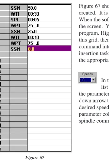
The B.E.V.I.S. commands are displayed in a list box on the main screen. This list box displays the commands available for creating programs. Clicking on the Insert button inserts the highlighted command (WTI, as shown in Figure 66) into the selected line in the program grid. Double-clicking on a line in this list box also inserts the command into the grid shown in Figure 67.
The icons to the left of the command descriptions indicate the type of command:
A command to wait for a condition.
A command to set a program parameter.
A command to send information to an attached printer.
Figure 67 shows the grid where the operator programs are created. It is used to view and edit the B.E.V.I.S. programs. When the software starts, an empty grid appears on the left of the screen. You can choose up to 25 commands for your program. Highlight each command in the list box to the right of this grid, then click on the Insert button to insert that same command into the highlighted line of the grid. This same insertion task can also be accomplished by double-clicking on the appropriate command in the list box to the right.
In the case of a speed command (SSN), the Speeds list box becomes enabled when the cursor is placed in the parameter column for an SSN command. Click on the down arrow to display a list of available speeds. Click on the desired speed, and it will be inserted into the appropriate parameter column in the program grid. The same applies to the spindle command (SSP).
Select the COM (RS-232) port the Programmable DV-II+ viscometer is connected to from the COM Port drop down list.
Click the Open File button to load existing B.E.V.I.S. programs.
Click the Save File button to save the B.E.V.I.S. program displayed in the grid.
Click the Print button to print the B.E.V.I.S. program displayed in the grid.
Click the Insert button to insert the B.E.V.I.S. command selected in the Commands box into the selected row in the program grid.
The buttons shown on the main screen are explained below.
Click the Delete button to delete the B.E.V.I.S. command in the selected row of the program grid.
Click the Up button to move the B.E.V.I.S. command in the selected row of the program grid up one row.
Click the Down button to move the B.E.V.I.S. command in the selected row of the program grid down one row.
Click the Clear button to clear the grid of all B.E.V.I.S. commands. Once cleared, the commands cannot be retrieved.
Downloads a B.E.V.I.S. program from the PC to the DV-II+
Exits the DVLOADER software program and returns the user to the WINDOWS Program Manager.
IV.4 Downloading a B.E.V.I.S. Program
Before down loading a B.E.V.I.S. program to the viscometer, ensure the following have been checked:
• The appropriate cable (BEL Part# DVP-80) is connected between the selected COM port of the PC and the viscometer.
• The DV-II+ motor must be OFF. • Set PC PROG to “OFF.”
• The Programmable DV-II+ is at the down load screen: OPTIONS|DOWNLOAD A
PROG|LOAD TO SLOT#x where x is slot 1,2,3, or 4. See Section III.6.
With the LOAD TO SLOT#x screen displayed, choose a storage slot using the DV-II+ arrow keys then press the ENTER/AUTO RANGE key on the viscometer. If after 5 seconds, the viscometer cannot communicate with the DVLoader program, the B.E.V.I.S.
ERROR NO PC ATTACHED message is displayed and a beeping sound is heard. If a
connection is established, the Down Load button on the PC software becomes enabled , and the DV-II+ screen displays DOWNLOAD PROG TO STORAGE SLOT #1. Click on this button to down load the displayed program to the DV-II+. When the down load is complete, the DV-II+ displays DOWNLOAD DONE TO EXIT PRESS A KEY.
Program 2: For use with an external temperature controller
Command Command Description Parameter Comments
WTP Wait for temperature 40.0 wait until temperature = 40°C (as
an example, a
Thermosel/Controller can be used for temperature control)
WTI Wait for time interval 05:00 soak time; allow temperature to
settle
SSN Set viscometer speed 25.0 run at 25 RPM
SPI Set print interval 00:30 begin printing data at 30 second
intervals
WTI Wait for time interval 06:00 wait at this step for 6 minutes,
effectively printing 12 data lines
Program 3: Wait for cure
Command Command Description Parameter Comments
SSP Set spindle 31 set to a number 31 spindle
SSN Set viscomter speed 100.0 run at 100 RPM
SPI Set print interval 00:05 begin printing data at 5 second
intervals
WPT Wait for % torque 85.0 wait until % torque = 85; a curing
cycle
Program 4: Spring relax
Command Command Description Parameter Comments
WKY Wait for a keypress Wind to 100% tell operator to wind spindle until 100% torque is reached
WPT Wait for % torque 100.0 wait until 100% torque is reached
WKY Wait for a keypress Release spindle tell operator to release the spindle
SPI Set print interval 00:01 begin printing data at 1 second
intervals
WPT Wait for % torque 0.0 wait for spindle to completely
unwind to 0% torque Program 1: Pre-shear
Command Command Description Parameter Comments
PLN Print text now Preshearing now print user message
SSN Set viscometer speed 50.0 run at 50 RPM
WPT Wait for % torque 90.0 wait unitl 90% torque is reached
PLN Print text now Collecting data print user message
SPI Set print interval 00:10 begin printing data at 10 second
intervals
SSN Set viscometer speed 10.0 run at 10 RPM
WTI Wait for time interval 01:40 wait at this step for 1 minute and 40 seconds, effectively printing 10 data lines
IV. 5 Example Programs
The following example programs can also be found on the DVLoader disk that was included with the DV-II+ Programmable Viscometer:
SSN Set viscometer speed 5.0 run at 50 RPM WTI Wait for time interval 00:10 wait for 10 seconds
PDN Print data point now print one data point
SSN Set viscometer speed 10 run at 10 RPM
WTI Wait for time interval 00:10 wait for 10 seconds
PDN Print data point now print one data point
SSN Set viscometer speed 20 run at 20 RPM
WTI Wait for time interval 00:10 wait for 10 seconds
PDN Print data point now print one data point
SSN Set viscometer speed 50 run at 50 RPM
WTI Wait for time interval 00:10 wait for 10 seconds
PDN Print data point now print one data point
Command Command Description Parameter Comments
Appendix A - Cone/Plate Viscometer Set-Up
This Cone/Plate version of the DV-II+ uses the same operating instruction procedures as described in this manual. However, the “gap” between the cone and the plate must be verified/adjusted before measurements are made. This is done by moving the plate (built into the sample cup) up towards the cone until the pin in the center of the cone touches the surface of the plate, and then by separating (lowering) the plate 0.0005 inch (0.013mm).
Programmable DV-II+ Cone/Plate Viscometers, S/N 50969 and higher, have an Electronic Gap Setting feature. This feature enables the user to easily find the 0.0005 inch gap setting that was established at Brookfield prior to shipment.
The following information explains how to set the Electronic Gap and verify calibration of the DV-II+ Viscometer.
A.1 ELECTRONIC GAP SETTING FEATURES
TOGGLE SWITCH allows you to enable/disable the Electronic Gap Setting Feature: left position is OFF (disabled), right position is ON (en-abled).
PILOT LIGHT is the red (LED) light; when illuminated, it means the Electronic Setting Function is sensing (enabled).
CONTACT LIGHT is the yellow (LED) light; when it first turns on, the “hit point” has been found.
SLIDING REFERENCE MARKER is used after finding the “hit point;” it is the reference for establishing the 0.0005 inch gap.
MICROMETER ADJUSTMENT RING is used to move the cup up or down in relation to the cone spindle. Turning the ring left (clockwise) lowers the cup; turning it right (counterclockwise) raises the cup. Each line on the ring represents one scale division and is equivalent to 0.0005 inch movement of the plate relative to the cone.
Pilot Light (red) Toggle Swtich Contact Light (yellow) Sliding Reference Marker Micrometer Adjustment Ring Figure A1
Bath/Circulator Bath Inlet Bath Outlet Sample Cup (CPE-44Y or CPE-44P) Cup Outlet Cup Inlet Figure A2 Figure A3 Spindle Wrench (CPE) Cone These surfaces must be clean! Coupling Nut Micrometer Adjustment Ring
Do Not hit the CONE with the CUP!
A.2 SETUP
1. Be sure that the Viscometer is securely mounted to the Laboratory Stand, leveled and zeroed with no cone or cup attached and 0% torque is displayed.
2. Figure A2 shows a typical water bath setup. Connect the sample cup inlet/outlet ports to the water bath inlet and outlet and set the bath to the desired test temperature. Allow sufficient time for the bath to reach the test temperature.
3. The Viscometer has been sup-plied with a special cone spindle(s) which con-tains the Electronic Gap Setting feature. The “CPE” part number designation on the cone verifies the Electronic Gap Setting feature. Note: The “CPE” cone or cup cannot be used with earlier DV-II+ cone/plate Viscometers (below S/N50969) which do not have the electronic gap setting feature.
4. With the motor off, thread the cone spindle by using the spindle wrench to secure the viscometer coupling nut (see Figure A3); gently push up on the coupling nut and hold this securely with the wrench. Thread the cone spindle by hand. Note: Left Hand Threads.
5. Attach the cup, taking care not to hit the cone with the cup (Figure A4).
The viscosity of electrically conductive fluids may be affected if readings are taken with the Electronic Gap Setting feature “on”. Be sure