Appendix E: Communications
To/From Vehicles
1
Table of Contents
1. Executive Summary ... 2
2. Introduction ... 3
3. Demonstrator Requirements ... 4
4. Machine to Machine Technologies ... 4
5. TV White Space (TVWS) ... 5
5.1. Weightless: a new radio protocol designed for M2M ... 6
5.2. Regulatory Environment ... 7
5.3. Outstanding issues ... 7
5.4. Future work ... 8
6. Demonstrator application for vehicle information ... 8
6.1 TV White Space coverage testing ... 14
7. High Level Design for national network ... 17
8. Use of existing cellular data networks ... 18
2
1.
Executive Summary
BACKGROUND
Strategic HA managed roads are “sensored”, but these are expensive to install and maintain.
Non HA roads (managed by Local Authorities) are hardly sensored at all, so there is very little data, especially when traffic is diverted off HA roads.
There are options to acquire data from devices such as satellite navigation systems, but these are viewed as expensive, and not available to all. They also suffer from the issue that when major events occur, cellular networks become over loaded so data connections could be lost.
There is a desire to pilot novel ICT solutions with the aim of demonstrating it is possible to deliver an information distribution service to and from vehicles in a cost effective manner that could lead to a compelling business case to justify wider deployment on a national scale.
This part of the project was set up to explore how ICT innovations such as smartphones, the internet of things and Machine to Machine technology can change the way in which road infrastructure is both used and managed and substantially reduce costs of information acquisition and distribution to drivers through applying new Internet of Things IT architectures.
Outputs
Investigated how much data is needed to provide a core transport information service to and from vehicles, and the associated wireless network solution architecture.
Developed a smartphone based application that can send and receive relevant data to and from vehicles, and a message protocol that can send this information with a limited amount of data.
Created a demonstrator based on this application plus an information distribution
component with the capability to route different information to different devices, based on the source of information or the location of a device.
Demonstrated sending and receiving small data packets (time, location, direction and speed within 40 characters) in a moving vehicle along the A14 over TV White Space (TVWS) spectrum.
Created a high level outline model for deployment of a network to cover Highway Agency roads with a set of assumptions about spectrum availability (bandwidth, power, duty cycle) and the availability of suitable locations for base station deployment along the HA road network that have power and backhaul capability.
FINDINGS
Whilst such a solution has been demonstrated over TVWS, the on-going uncertainty around TVWS regulation both with respect to timing and operational parameters such as output power has meant that a number of technology suppliers are looking at other unlicensed spectrum options, such as the 458 and 868 ISM bands. Whilst they operate in a slightly
3 different spectrum, they have many of the same characteristics as TVWS, such as long range and low power consumption.
Trials using the current technology cannot be taken any further due to lack of equipment, as suppliers move to new equipment based on using different radio spectrum.
Issues remain over the best choice of spectrum and wireless technology to enable such a service and more work is required to enable accurate business models to be produced. TVWS is dependent on regulations from Ofcom on output power, and the size of antenna that could be produced for vehicles. Alternative options include other unlicensed bands, specific spectrum as in the GSM-R solution for rail or general cellular data networks such as 3G and 4G.
NEXT STEPS
Further trials could be carried out in the short term using standard cellular communications.
Longer term opportunities still exist around new M2M protocols, and given suitable
spectrum (bandwidth, transmit power and duty cycle), then such information could be sent over radio networks using unlicensed spectrum..
2.
Introduction
The major strategic roads operated by the Highways Agency are well instrumented and provide a range of data about current conditions and journey times. However, this infrastructure is relatively expensive to install and maintain, and there is little data provision away from major roads, making it difficult for local authorities and drivers to understand current conditions of local roads, especially when incidents occur.
The key aim of this work is to explore whether the use of new “machine to machine” technologies, along with novel wireless connectivity solutions, could be used to demonstrate innovative ways to gather and distribute information, enabling road infrastructure owners to manage their assets more efficiently in both normal and abnormal circumstances, and for drivers to have better information relating to their journeys.
The technical work within the demonstrator was broken down into three areas:
a) An application that could run on a smartphone, combined with a suitable protocol and API so that information can be received and displayed, and also autonomously gather
information about vehicle location and speed.
b) An information distribution platform to collect information from vehicles and other sources and which implements various rule sets around distribution and access to information; and to demonstrate that it is possible to develop an information distribution service that can be used by developers to create new applications.
c) Exploration of new cost effective network technologies. Research whether unlicensed spectrum, such as TV Whitespace, could be used as a cost effective means to provide a level of communication with vehicles and travelers; understand the trade-off between bandwidth and information sent and received; consider the options for economic deployment of base stations to cover all vehicles within an area with an adequate bandwidth – this includes in extreme circumstances i.e. major congestion.
4
3.
Demonstrator Requirements
The requirements for this report and the demonstrator were broken down into several work streams:
1. Develop an application to collect and receive transport related information
a. Be able to automatically generate information about the vehicle (speed, location, direction).
b. Be able to display information in an easy to understand and non-distracting manner. c. Develop an API and protocol to pass information over a low bandwidth network to
an information hub.
2. Use of low power wide area unlicensed spectrum as a cost effective means to provide communication to and from vehicles
a. Develop a mechanism to enable a mobile phone to connect to terminals that use such a spectrum.
b. Test coverage patterns on the Highways Agency and local council controlled roads around Ipswich from base stations at Kirton, Martlesham, and Belstead.
3. Develop an information service with a process model that demonstrates collection of data and how this can be shared with a data hub and then onwards to a range of devices. Demonstrate receiving messages from a variety of sources, including in-vehicle devices, to an Information Distribution platform and onward display of these messages to different devices depending on the rule set within the Information Distribution platform.
i. Demonstrate that trusted information can be distributed to all interested parties.
ii. Demonstrate that vehicle generated data can be distributed to specific other vehicles.
iii. Demonstrate that private data, such as from the emergency services, can be sent to the hub but only shared with other parties that have the relevant access permissions to that data.
4. Build a concept demonstrator to show how a trial application could work with an Information Distribution architecture.
a. Ability to demonstrate in a stand-alone environment using local connectivity (Wi-Fi). b. Demonstrate working on a road using TVWS.
5. Develop an outline architecture and model for a national system covering highways agency and local authority managed roads (bandwidth and coverage requirements, number of base stations etc.).
4.
Machine to Machine Technologies
Machine to Machine (M2M) technologies cover the broad area of connecting devices and sensors to a network, which then operate without human intervention. This could be uplink only (such as a sensor sending data from a fire alarm to a back end server) or include a downlink (to an actuator or something that carries out actions, such as automatic fire extinguishers). There are many analyst reports about the expected huge number of connected devices (expected to be measured in billions), which leads to some general characteristics that distinguish machine to machine networks from traditional communication networks, the key ones being:
1. Large number of nodes (sensors, actuators)
2. Each generates small amounts of data
5
4. Energy efficient (run off battery for several years)
5. Good coverage (long range and in building)
6. Global standard
7. Cost effective (low £ per year for connectivity)
8. Small latency acceptable (few seconds)
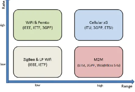
M2M devices will be used for an enormous variety of applications with different communications requirements. However, connecting all the potential end devices, wherever they may be, is a significant engineering challenge. These devices will be spread across a wide variety of locations, some of which will be hard to reach – either because they are remote and outside the range of most communications networks, or because they are underground or deep inside buildings. There isn’t one single technology that can connect all of these devices and current applications use a patchwork of different approaches. However, new solutions are emerging that are designed specifically for M2M and one of the innovative aspects of the trial was to look at using unlicensed low power spectrum in the sub 1GHz band, as this should have the long range and low cost characteristics required for several use cases.
Figure 1shows how the different wireless technologies compare to each other for data rate and transmission range. This report focusses on the bottom right portion – long range and low data rate.
Figure 1: Wireless Taxonomy
5.
TV White Space (TVWS)
TV White Spaces are gaps left between broadcast channels in different places on different channels and are not being used for the delivery of digital terrestrial television services in a given geographic area. Usually, the white spaces have only been used by wireless microphones (for Program Making and Special Events, referred to as PMSE), on a licensed basis.
TVWS has the following characteristics that make it favourable for M2M system:
6
• Deep penetration inside buildings (1<GHz).
• Globally harmonised (allow devices to roam internationally and for economies of scale). Figure 2 illustrates the opportunities for shared spectrum in TVWS between 470 MHz and 790MHz.
Figure 2: Overview of TVWS
5.1.
Weightless: a new radio protocol designed for M2M
Weightless has been created as a protocol to meet requirements of M2M, as there was a lack of suitable standards, and as explained above, M2M solutions are different from existing technologies both technically and commercially.
The key requirements that drove the creation of Weightless were:
Ultra-low cost: <$10 modules reducing to <$5 in a few years
Excellent coverage: Up to 10km with 1W BS and ~40mW terminals
7
QoS: Bi-directional communication link, with ACK/NACK
Scalable: Lightweight and high availability
Data rate: Few Kbits/s
5.2.
Regulatory Environment
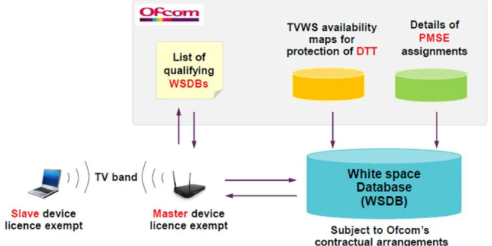
The extent of protection afforded to existing licensees is unknown, which will impact both the amount of spectrum available and also the output power levels that transmitters can use. The proposed UK regulatory environment will be based on a database containing allowed channels and power levels for every location in the UK (based on a 100m square). Any given white space
transmitter will need to consult this database and will receive back information on available frequencies and powers which are available for use, as shown below.
Figure 3: Framework for access to TVWS in the UK
5.3.
Outstanding issues
There are a few outstanding issues in relation to TVWS
Regulatory Environment: Timing – the timetable for regulation of TVWS has been delayed and is still uncertain
The spectral range of TVWS impacts the practical deployments, in that power amplifiers that operate across the band are relatively expensive, and a large antenna is needed for tuning across the entire band, impacting size and cost of terminal equipment
There are no QoS guarantees in unlicensed spectrum
Limited number of vendors (chipsets, base stations and terminals)
Weightless has not yet been endorsed by standard bodies (IEEE, ETSI, etc.)
Whilst this section has focussed on TVWS, there are other unlicensed bands available that offer similar coverage characteristics that can also be used.
8
5.4.
Future work
There is still a large degree of uncertainty around the best radio solution to use. This can be split into the protocol and then spectrum. Weightless appears to be a suitable protocol for M2M, has a reasonable number of application developers in the SIG, but is lacking in terms of major industry players support for chips and devices, as well as issues over real world coverage ranges, size of antenna needed at the terminals and cost of power amplifiers.
There is also the issue of spectrum. Under the current proposed Ofcom regulations, the need for a terminal to tune over the whole spectrum range of TVWS (490MHz to 780MHz) is the cause of the antenna and power amplifier issues, and the expected allowed level of transmit power may cause coverage issues (low transmit power = less coverage).
It may be worth exploring other wireless solutions and potential spectrum options, such as: a) Dedicated channels from current TVWS spectrum being allocated for M2M use.
b) Using other unlicenced bands and modifying existing regulations (such as raising duty cycle from 2.5% to 10% for ISM bands).
c) Exploring other industry initiatives, such as DASH7 or Low power Wifi (802.11ah) or other potential suppliers of long range wireless networks suitable for M2M, such as Sigfox, SilverSpring or Onramp to determine whether they could provide variants suitable for moving vehicles.
d) Option to transition Weightless from TVWS to other unlicensed or licenced spectrum if needed, e.g. when 700MHz auctioned, or as a licensed shared user of military spectrum. e) Use of existing cellular data.
Further work is required to explore these options to understand the impact on technical operation of the application proposed, and impact on business model (cost and number of base stations, coverage patterns and bandwidth required, cost of terminal devices).
6.
Demonstrator application for vehicle information
The application developed built upon existing work from the STRIDE1 project. A demonstrator was built to show various features such as
1. Distribution of information to devices in vehicles.
2. Ability to control what information is distributed to which devices. 3. Display of information to driver in a useable non-intrusive manner. 4. Collation of data from devices in vehicles.
5. Ability for drivers to easily input simple information.
The example application was built to be independent of the underlying network connectivity. For the demonstrator, Wi-Fi is used to provide local connectivity between devices. There are a number of devices needed for the demonstrator:
a. A PC acting as the Information hub to collect and distribute information. The PC has a Wi-Fi access point to which all other devices connect.
1
9 b. A Nexus 10 tablet, acting as a graphical interface onto the Information distribution
platform.
c. A Nexus 7 tablet, acting as the National Operations Centre to provide trusted information.
d. A Nexus 7 tablet, acting as an example Highways Agency gantry sign to display the information.
e. Two Nexus 4 phones, acting as two vehicles, to demonstrate information generated by a vehicle and the ability to send information to a vehicle but not to a gantry sign.
Figure 4: Overview of demonstrator devices
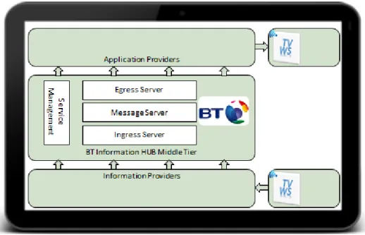
The Transport information Hub emulates the Information Distribution Platfrom built in the STRIDE project. It displays all messages received from the various sources, and carries out simple
information routing rule sets. For the demonstrator, three rule sets were implemented. Firstly, information from the National Operations Centre was sent to gantry signs and all vehciles as this was viewed as a trusted source. Secondly, information from a vehicle was only sent to the other vehicle (not to the gantry sign). Thirdly, information from emergency services wassent to the hub but not distributed to either the gantry signs or the vehicles.
10
Figure5: Transport Information Hub with no information present
Figure 6: Transport Information Hub with a range of information sources
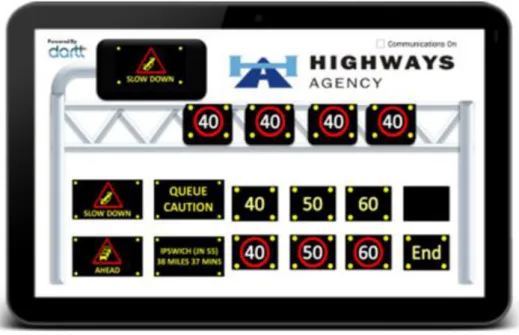
The tablet acting as the Operations Centre enables various standard messages to be sent to the information hub. The messages that could be sent for the demonstrator are any of the signs shown in Fig 7.
11
Figure 7: Information options from tablet acting as National Operations Centre
The tablet acting as a gantry then receives and displays any messages sent from the National Operations Centre tablet to the Information Hub tablet.
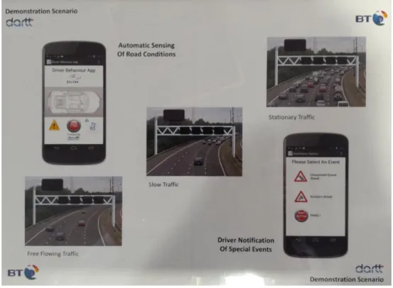
12 The next part of the demonstrator shows information generated by a vehicle being sent to the Information Distribution platform. For a live trial, the Driver Behaviour Application from the STRIDE project would be used to generate data from a vehicle, such as slow or stopped traffic. In order to generate messages for the demonstrator, a simple display board was constructed, using RFID tags to represent different conditions, such as free flowing, slow or stationary traffic, and also to provide simple driver responses, such as press a button to indicate an accident or queue. By touching one of the phones representing a vehicle to the appropriate RFID tag on the display board, the phone would generate a message according to the information contained within the tag and as represented by the pictures on the display board. The display board is shown in Fig 9.
Figure 9: Display board to illustrate different road conditions
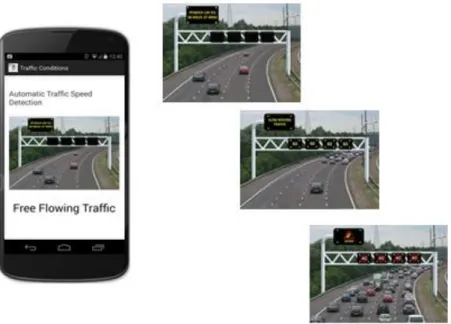
Either of the phones can be touched against the three images of roads, and this will result in an appropriate message (free flowing, slow or stationary traffic) being generated by the phone and sent to the Information hub. The rule set in the Information Hub is that this message should only be sent to the other phone, and not to the gantry.
13
Figure 10: Example of different road conditions detected by phone
The other phone will receive the message and display an appropriate sign, and there is also a text to speech capability so that an audio representation of the message is heard by the driver, and the driver is not distracted by having to look at the screen.
14
6.1 TV White Space coverage testing
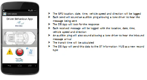
As a second phase to the work, coverage of the TV White Space signal was measured along the A14 and A12 and various roads in Ipswich. For this, the existing STRIDE Driver behaviour application was amended to enable the GPS location, date, time, vehicle speed and direction to be sent to the Information Spine platform over TV White Space, which then responded with an acknowledgement. The total transit time for the message was also recorded as a crude measure of system coverage and reliability.
The process flow for this was as follows:
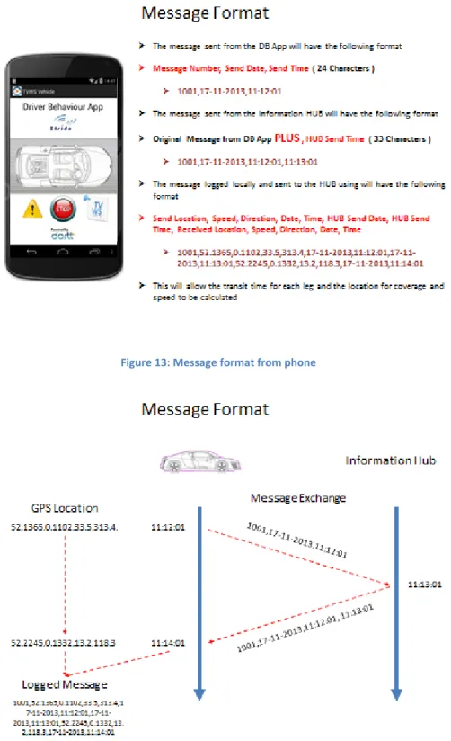
1. The phone creates a message containing GPS location, speed, direction and time. 2. This is sent over TVWS to an application where a response is generated.
3. The response, including a timestamp, is sent back to the phone over TVWS.
4. The total time taken for the message to be sent and received is then recorded, and plotted against the location when the message was received.
This is shown in the following diagrams.
Figure 12: STRIDE Driver Behaviour Application as used to test TVWS coverage
15
Figure 13: Message format from phone
Figure 14: Overview of end to end message formats
In order to test the coverage, journeys were made around Ipswich on the A12, A14 and local roads, making use of three TVWS base stations located at Adastral, Kirton and Belstead (top right, bottom right and top left red circles in figure below). The route taken for the test is shown below, along with the location of the three base stations. Each blue arrow represents a GPS measurement.
16
Figure 15: Coverage obtained from TVWS base station on roads around Ipswich
These GPS positions were sent using TVWS to the Information Hub, which then responded and the total time taken for the acknowledgment to be received in the vehicle was recorded, using the messaging protocol above. The delay was then colour coded depending on the length of time taken, and plotted against the original GPs positions to give an indication of coverage.
Figure 16: Overview of coverage (colour coded based on delay times)
It can be seen there are several gaps in coverage, due to:
a. Signal degradation due to local terrain (buildings, trees). b. Time taken to handover between base stations.
17 c. General signal propagation loss as distance increases from base station.
7.
High Level Design for national network
In order to create an outline network design, several assumptions need to made, many of which require further validation to ensure robustness. The key considerations relate to the coverage and bandwidth needed.
In terms of bandwidth, it can be assumed that within a “cone of interest” (such as Eastbound along the A14 within a 5 mile stretch), then the same information would be sent to all vehicles (e.g. queue ahead) and as such could be broadcast, so bandwidth to vehicles is not considered a major issue. In terms of information from vehicles, it is necessary to allow for messages from multiple vehicles. A worst case situation could be envisioned as a three lane motorway, with stationary traffic in both directions.
Key requirements as input to the high level design were as follows:
Ability to collect vehicle information on position, speed, direction and time.
Ability to broadcast sign/warning messages.
Data requirements:
o Individual uplink messages from vehicles every 30s.
o Occasional broadcast downlink messages.
Coverage of UK motorways, trunk and principal A-roads:
o 3618km motorways
o 8507km Trunk A-roads
o 38235km principal A-roads
In order to translate these requirements into a capacity estimate, there is the need to make further assumptions on location and design parameters:
Base stations located at optimal positions (e.g. bridges) with power and backhaul network available.
Directional base station antenna.
6dB base station antenna gain.
Unidirectional, compact vehicle antenna with 0dB antenna gain.
In-vehicle loss 5dB.
Standard path loss and Doppler models.
Suitable clean licenced spectrum available in the <1GHz range with 200kHz bandwidth, 1W transmit power (uplink and downlink) and no duty cycle constraints.
The Uplink Link budget is the key parameter to define the overall path loss, which in turn drives the coverage patterns. Another set of assumptions are used:
Transmit power 30dB.
Vehicle antenna gain, 0dB.
Base station antenna gain, 6dB.
Base station thermal noise floor @ 200 kHz, -121dBm.
Base station noise figure, 3dB.
18
Implies a maximum path loss of 153dB.
Taking these assumptions as a reasonable starting point to base a design on, a summary of the findings is that:
Broadcast downlink payload is negligible.
Downlink capacity for acknowledgement/security/control dominates.
Aggregate Uplink capacity much greater than downlink.
~2091 base stations required for UK motorways and trunk A roads.
~8683 required to include principal A roads.
More detailed geographic coverage/overlap analysis is required when details of base station installation locations would be known.
8.
Use of existing cellular data networks
Even though one of the starting points for this work is that existing cellular data networks become overloaded during incidents (e.g. people in vehicles start using smart phones for various applications and use up all available bandwidth), it is instructive, and a sanity check, to carry out a high level analysis of whether such an application as described above could run over existing cellular networks, especially as any further trials in the short term would use smart phones which are already
connected to such networks.
In order to estimate the amount of data that would be required to support a national service, the following assumptions were made. These are indicative only, and need to be further validated, but can be used as a rough sizing model.
For information from a vehicle (speed, location, time)
Message size (bytes) 50 Message frequency (seconds) 30 Average number of hours in use per day 3
Number of vehicles in UK 30 million Percentage of vehicles on road at peak time 50%
If it is assumed that information sent to vehicles in 50% of the total traffic that is created by the vehicles (i.e. vehicles send twice as much data as they receive), then the total data per day to run a national service is the order of 130,000MByte. This is a single figure percentage of total data expected to be passed over cellular networks in the UK by 2018, and it is also expected that the cost of transmitting this data would be in the low millions of pounds per year.
19
9.
Conclusions and Next Steps
Further trials could be carried out in the short term using standard cellular communications. Such trials would validate the application and back office requirements and data processing systems and features such as what information is needed from vehicles and how often, how is the information gathered and collated, what information is required to be sent to vehicles, how to define a cone of interest for a vehicle to determine what information to send, how many vehicles would need devices to make meaningful comparison against existing data on road conditions etc.
Longer term opportunities still exist around new M2M protocols, and given suitable spectrum (bandwidth, transmit power and duty cycle), then such information could be sent over radio networks using unlicensed spectrum. Assuming a TVWS or other suitable unlicensed spectrum scenario, a very high level initial analysis, assuming availability of suitable base station locations with power and backhaul network, and 200kHz of spectrum with ~1W output power in a <1GHz band, showed around 9,000 base stations would be needed for a viable future national network to support communications to and from moving vehicles across the UK road network, but further work is required to validate the assumptions and prove the model. The cost of such a network roll out is highly dependent on transmit power (the more power the larger the coverage area, hence fewer base stations) and availability of suitable sites/locations for the base stations.
20
Offices worldwide
© British Telecommunications plc 2004
Registered office: 81 Newgate Street, London EC1A 7AJ Registered in England No: 1800000