General Information Guide
Release 4.0
by Mitel Networks™ Corporation (MITEL®). The information is subject to change without notice and should
not be construed in any way as a commitment by Mitel or any of its affiliates or subsidiaries. Mitel and its affiliates and subsidiaries assume no responsibility for any errors or omissions in this document. Revisions of this document or new editions of it may be issued to incorporate such changes.
No part of this document can be reproduced or transmitted in any form or by any means - electronic or mechanical - for any purpose without written permission from Mitel Networks Corporation.
Trademarks Mitel, MiTAI, ACD TELEMARKETER, SUPERCONSOLE 1000, Speak@Ease, Mitel Express Messenger, TALK TO, ANSWER PLUS, Unified Communicator and NuPoint Messenger IP are trade-marks of Mitel Networks Corporation.
Windows and Microsoft are trademarks of Microsoft Corporation.
Adobe Acrobat Reader is a registered trademark of Adobe Systems Incorporated. Linux is a registered trademark of Linus Torvalds.
Other product names mentioned in this document may be trademarks of their respective companies and are hereby acknowledged.
Mitel Communications Director General Information Guide
Release 4.0 Rev. A July 2009
®,™ Trademark of Mitel Networks Corporation © Copyright 2009, Mitel Networks Corporation
About this Document . . . 1 Overview . . . 1 Audience . . . 1 Related Documentation . . . 1 Overview . . . 3 Platforms . . . 3
Modular Platform Design Provides Scalability and Flexibility . . . 3
About the 3300 ICP . . . 3
About Mitel Communications Suite for Sun Servers . . . 5
Applications that Enhance Productivity . . . 5
Devices that Support the User . . . 6
Powerful Tools Minimize Configuration and Support . . . 6
Extensive System Feature Set . . . . 6
Migration Made Easy . . . 7
3300 ICP System Description . . . 9
3300 ICP System Architecture . . . 9
Mitel Communications Director Software . . . 10
Controllers . . . 10
CX and CXi Controllers . . . 11
AX Controller . . . 14
MXe Controller . . . 16
MXe Server . . . 18
Analog Support . . . 20
Quad Copper Interface Module (CIM) . . . 20
Analog Services Unit II . . . . 20
Analog Main Board/Analog Option Board . . . 21
Digital Trunk Support: Units and Modules . . . 22
Dual Fiber Interface Module (FIM) . . . 22
Universal Network Services Unit . . . 22
R2 Network Services Unit . . . 23
Dual T1/E1 Framer Module . . . 24
T1/E1 Combo Module . . . 24
Quad Basic Rate Interface (BRI) Framer Module . . . 24
SX-200 Bay Support . . . 25
SX-200 Cabinet . . . 25
SX-200 Peripheral Cards . . . 25
Peripheral Interface Module Carrier Card . . . 26
Processors (E2T/RTC) . . . 26
Digital Signal Processor Modules . . . 26
Echo Cancellation Module . . . 27
Applications Support . . . 27
Firewall (CXi, MXe and MXe Server only) . . . 28
3300 ICP Network Support . . . 29
Voice Networking . . . 29 Lines . . . 29 Trunks . . . 29 IP Networking . . . 30 SIP Trunking . . . 31 Compression . . . 35 Bandwidth Management . . . . 36 Resiliency . . . 37
Advantages Over Redundancy . . . 39
Devices that Support Resiliency . . . 40
Rapid Spanning Tree Protocol . . . 40
Gateway Solutions . . . 41
Live Business Gateway . . . 42
PC-to-Phone Support and the 3300 IP Communications Platform . . . 44
Migrating to the 3300 ICP . . . 47
SX-2000 Adjunct . . . 47 SX-2000 Control Replacement . . . 48 SX-200 Control Replacement . . . 49 Non-Mitel Products . . . 49 Non-Mitel PBX Adjunct . . . 49 Applications . . . 51
Mitel Unified Communicator . . . 51
Mitel Unified Communicator Express . . . 51
Mitel Unified Communicator Advanced . . . 52
Mitel Unified Communicator Advanced Softphone . . . 58
Mitel Your Assistant Collaboration Option for UC Advanced . . . 59
Mitel 5300 Intelligent Directory Application . . . 60
Mitel 5300 Intelligent Directory Presence Option . . . 60
Conferencing and Collaboration . . . 60
Mitel Live Business Gateway . . . 61
Quick Conference . . . 62
Mobility Solutions . . . 64
Hot Desking . . . 64
Teleworker Solution . . . 65
Mobile Extension . . . 67
Wireless Support (3300 ICP deployments only) . . . 68
Messaging . . . 73
Embedded Voice Mail . . . 73
Mitel NuPoint Messenger IP . . . 74
Mitel Messaging Server . . . 76
Customer Interaction Solutions . . . . 79
Automatic Call Distribution . . . 79
Applications for Formal Contact Centers . . . 80
Applications for Informal Contact Centers . . . 82
Mitel Call Accounting . . . 82
Mitel Applications Suite . . . 84
Hospitality . . . 85
Hotel/Motel . . . 85
Property Management System . . . 86
General Business Solutions . . . 88
Tenanting . . . 88
Emergency Services Support . . . 89
Emergency Response Advisor . . . 89
Multi-Level Precedence and Preemption (MLPP) . . . 90
Mitel Call Accounting . . . 91
Third-Party Developer Support . . . 92
MSA Universal SDK Development Kit . . . 92
MiTAI . . . 92
MiTAI and MiAUDIO . . . 92
MiAUDIO . . . 93
Secure Recording Connector . . . 93
HTML Toolkit for 5330 and 5340 IP Phones . . . 93
Tools . . . 95
End User Tools . . . 95
Desktop Tool . . . 95
Administrator Tools . . . 96
Group Administration Tool . . . 96
System Administration Tool . . . 97
Management Tools . . . 98
Enterprise Manager . . . . 98
System Data Synchronization . . . 100
Management Access Point . . . 101
Maintenance Tools . . . 101
AMC Licensing . . . 101
MCD Software Installer . . . 102
Mitel Integrated Configuration Wizard . . . 103
Line Measure Tool . . . 103
Alarms Management . . . 104
Remote Alarms Notification . . . 104
Controlled System Access . . . 104
IP Phone Analyzer . . . 105
ISDN Maintenance and Administration Tool . . . 105
Desktop Devices . . . 107
Feature Support Matrix . . . 107
Basic IP Phone . . . 110
Display Phones . . . 111
Desktop Application Phones . . . 113
Mitel Navigator . . . 115
Mitel 5560 IPT . . . 117
Wireless IP Phones (3300 ICP deployments only) . . . 118
IP Phone Accessories . . . 119
Mitel IP Programmable Key Modules . . . 120
Mitel 5310 IP Conference Unit . . . 121
Line Interface Module . . . 121
Cordless Handset and Headset . . . 122
Mitel Wireless LAN (WLAN) Stand . . . 123
Mitel Gigabit Ethernet Stand . . . 123
Mitel IP Paging Unit . . . . 124
Mitel 5550 IP Console . . . 125
Digital Phone . . . 126
SUPERCONSOLE 1000 . . . 127
Digital Phone Accessories . . . . 127
Mitel Programmable Key Modules . . . 127
SUPERSET Interface Module 2 . . . 128
Features . . . 129
Features of Mitel Communications Director . . . 129
Auto Attendant Features . . . 152
Features supported by protocols . . . 157
QSIG . . . 157
PRI . . . 159
MSDN/DPNSS . . . 160
Security Features . . . 161
Encrypted Media Path and Signaling Path . . . 161
Phone and User Authentication . . . 161
Worm and Virus Protection . . . 161
Prevention of Toll Abuse . . . 161
Secure Management Interfaces . . . 162
Secure Applications . . . 162
SIP Security . . . 162
Product Availability by Region . . . 163
North America . . . 163
Asia Pacific . . . 165
EMEA Region . . . 167
Latin America . . . 169
About this Document
Overview
This guide provides an overview of the Mitel® Communications Director (MCD) call-processing
software and its host hardware platforms, the Mitel® 3300 IP Communications Platform (ICP)
and Mitel Communicaitons Suite for Sun Microsystems® servers. The topics covered in this
guide include
• description of the system architecture and components • migration strategies
• supported applications.
Audience
This guide is for • end customers • sales executives • consultants • industry analysts • media analysts • sales engineers • system engineers.
Related Documentation
Go to the Mitel Customer Documentation web site at http://edocs.mitel.com to access Mitel documentation. You require a Mitel Online account username and password to view and download technical documentation. However, you do not need a username and password to view and download end user documents (such as telephone user guides).
The following guides provide complete information about MCD and the 3300 ICP: • General Information Guide provides an overview of the system.
• Site Planning Guide provides site planning and site preparation guidelines.
• Technician's Handbook provides installation, upgrade and maintenance instructions. • Hardware Technical Reference Manual provides hardware specifications.
• System Administration Tool Online Help provides programming, maintenance, and trou-bleshooting procedures.
• Troubleshooting Guide provides information on diagnosing and resolving common prob-lems with the 3300 ICP.
• Resiliency Guidelines provides a comprehensive overview of the Mitel Resiliency solution and offer customers the tools to understand, plan, and implement a resilient network. • Engineering Guidelines provides the information that is required to engineer a 3300 ICP
system for a customer site. The guidelines are intended to highlight specific areas of the product that need to be considered before installation.
For information on Mitel Communications Suite, refer to the following documents:
• Mitel Communications Director Installation and Administration Guide for Mitel Communi-cations Suite (MCS) describes the installation, administration, maintenance, and troubleshooting of the MCD software blade.
• Mitel Communications Director for MCS System Administrator Online Help provides ad-ministration and programming procedures for the MCD software blade.
• Mitel Communications Suite Engineering Guidelines provides information on implementing MCS. Topics covered include licensing, system requirements, capacities, performance, and supported configurations.
Overview
MCD provides businesses of all sizes with a highly scalable, feature-rich communications system. It’s designed to meet the needs of businesses from 5 to 65,000 users whether they are single-site deployments or multi-site networks that span many countries.
Platforms
MCD runs on the following hardware platforms:
• Mitel 3300 ICP controllers, including MXe, MXe Server, CX and CXi
• Sun Microsystems® servers (as a component of Mitel® Communications Suite)
Modular Platform Design Provides Scalability and Flexibility
Whether deployed on the 3300 ICP or a Sun server as part of MCS, MCD has a modular and scalable system design that allows customers to invest in a hardware platform to meet their current requirements and then increase the size of the system as their business expands. The core call control components are the same regardless of the hardware platform, and
functionality, such as trunk support, is provided through field-installed modules. This hardware commonality ensures that as a business grows the majority of a customer’s investment is protected when a controller chassis is upgraded.
About the 3300 ICP
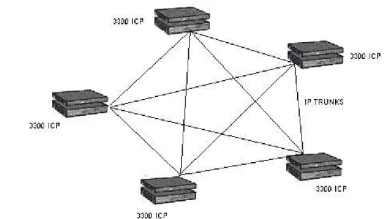
The 3300 ICP can be deployed to support a broad spectrum of site configurations. For example, a highly centralized solution can be implemented at the head office with the call control and IP telephony services delivered over wide-area-network connections to small branch offices. Larger branch offices can be configured with a main controller on site to provide local support. Finally, an entire network of controllers can be clustered to function as one large system.
Figure 1: 3300 ICP Site Configuration
For smaller organizations, Mitel delivers a system which incorporates a powered Ethernet switch and an embedded processing card that hosts applications such as Teleworker, Mobile Extension and Live Business Gateway, essentially delivering all the voice communications capabilities a small business needs in a single chassis. For example, a CX Controller can support a 40-person business with embedded voicemail and auto attendant, as well as house a connection to the public network and host applications like Teleworker – all from a single chassis.
For large organizations or multi-site deployments, up to 999 controllers can be deployed in a cluster to deliver extensive features, services, and applications. These controllers use a peer-to-peer communication protocol to ensure management and administration data is shared between systems thus ensuring consistency of features and applications for the users without incurring high management costs.
On large sites, key functionality is typically hosted by dedicated “task-specific” controllers with all users connected over an IP network; for example a large organization might have
• 4000 users on an MXe Server (primary) with a backup MXe Controller to provide resilient support
• an MXe Controller acting as a trunking gateway with connections to the traditional telephone network for outside access, and
• a dedicated NuPoint Messenger Server for voicemail, automated attendant, and unified messaging.
Networking With Industry-Standard Protocols
Use of open standards, such as SIP, interconnects next generation network services and applications to support new desktop devices. Customer can be assured that their investment in a Mitel solution will be developed and expanded into the future because the solution is not limited by proprietary protocols. And while our focus is to deliver a complete communications solution that meets the needs of today with potential to deliver more in the future, our solution also supports an extensive list of legacy protocols and devices.
Reliability Through Redundancy and Resiliency
For mission-critical environments, you can provision the 3300 ICP with hardware redundancy and resiliency. Resiliency automatically transfers support for an IP phone to an alternate controller in the event that the phone cannot communicate with its primary controller. By taking advantage of IP-networking, resiliency provides an extremely flexible solution to enhance system reliability. It uses resources that are spread across the network to optimize hardware resources and ensure that there is no single point-of-failure.
Mitel’s resiliency solution uses Spanning Tree Protocol and Rapid Spanning Tree Protocol (STP/RSTP). These protocols allow physical path redundancy between Ethernet switches. They place redundant network paths into standby mode by blocking traffic on redundant ports. Then, if a currently active network path fails due to a Bridge/Switch failure or a network cabling failure, STP/RSTP enables a standby network path and network connectivity is restored.
About Mitel Communications Suite for Sun Servers
Mitel Communications Suite allows Mitel’s Mitel Communications Director software to reside on Sun Microsystems® servers along with other Mitel voice applications. This solution preserves the functionality and features of the traditional 3300 ICP as well as the other embedded applications and allows organizations to carry voice-based solutions on a Sun data infrastructure. It is the perfect solution for all businesses looking to reduce install times; to get secure, centralized management; and to lower their total cost of ownership.
Aimed at reducing the number of deployed servers as well as the complexity of the installation, Mitel Communications Suite integrates:
• Call control: Mitel Communications Director • Voicemail: Mitel NuPoint™ Messenger
• Microsoft® integration: Mitel Live Business Gateway • Thin client integration: Mitel Unified IP Client for Sun Ray™
Applications that Enhance Productivity
MCD boasts an extensive number of applications that provide significant value to an organization and its employees. Applications are available to enhance communication, productivity, accessibility, mobility, as well to support the specialized site requirements of businesses and institutions, such as hotels, hospitals, schools, military sites, and call centers.
Mitel Networks also supports the integration of third-party applications through the Mitel Solutions Alliance (MSA). If your business requires custom applications or features to achieve higher productivity, this program enables you to develop them.
Devices that Support the User
Mitel has a wide selection of attractive, easy-to-use IP devices to meet the needs of employees, managers, executives, and attendants. These IP devices provide quick access to the system’s powerful features through programmable feature keys, softkeys, and menu-guided applications such as Call Forwarding and Call History. Mitel provides:
• Basic IP Phones • Display Phones
• Desktop Application Phones • Wireless Phones
• Session Initiation Protocol (SIP) Phones • Consoles
• Conference Units
• Video Conferencing Devices • Digital Phones
• Phone Accessories.
Powerful Tools Minimize Configuration and Support
Installation, configuration, and administration are minimized and simplified through a series of powerful tools. These tools are designed to ensure that the target audience — end-user, group administrator, system administrator, or installer can perform their functions quickly and easily. • End user tools allow users to maximize the value of the system features.
• Administrator tools simplify system and user configuration.
• Management tools automate the tasks required to support large scale installations. • Maintenance tools reduce the time and costs associated with system support.
Extensive System Feature Set
MCDhas an extensive list of end-user and system features that support effective and efficient communications. The system administrator can enable or disable features through the System Administration Tool and can create Classes of Service to define levels of feature support for each different group of users. For example, a Class of Service can be created to provide executives with advanced calling privileges, such as Executive Busy Override.
Administrators can also enable or disable system settings across the entire system or network. Although the features and system settings are configurable to allow maximum flexibility, usable default settings minimize configuration requirements.
Migration Made Easy
Because of Mitel’s long history in voice communications, we continue to support a host of protocols which facilitate a smooth migration to Voice over IP support – whether your legacy PBX is from Mitel or another supplier.
You can deploy the 3300 ICP as a network gateway to link multiple traditional PBX’s together over a WAN connection, eliminating costly private circuits. Or, you can deploy it as an applications gateway that delivers critical functionality to a defined user community without disrupting the broader organization. These deployment models allow organizations to migrate at their own pace, when it suits their needs.
3300 ICP
System Description
This chapter describes the 3300 ICP system functionality. For details on system configurations, refer to the Engineering Guidelines. For detailed descriptions of the hardware components, refer to the Hardware Technical Reference Manual.
3300 ICP System Architecture
The 3300 ICP delivers sophisticated call management applications and desktop solutions for businesses. Mitel delivers a highly scalable, resilient, robust call control that fully utilizes the power of IP while fully supporting the traditional TDM based telephony for legacy devices and PSTN connectivity.
Mitel’s architecture uses the IP network to connect IP telephony devices. It also switches calls between traditional telephone devices:
• For IP telephony, it provides call setup, tear down, and signaling between Ethernet IP connected telephones.
• For traditional telephony, such as POTS and PSTN trunks, it handles calls via a conventional TDM circuit-switched subsystem.
This ability to use two different switching techniques simultaneously means that:
• All traffic is switched with minimum conversion between packet and traditional telephony to provide optimum voice quality in all call scenarios.
• Embedded gateway functionality is only required between the IP and non-IP networks optimizing the use of system resources.
• Migration from traditional PBX to IP telephony is seamless and efficient
Mitel Communications Director
Software
The Mitel Communications Director software provides the call control features and applications that enhance business communications. The software is packaged for a variety of site capacities – but ultimately all sites, regardless of size, have access to the same extensive feature set.
Controllers
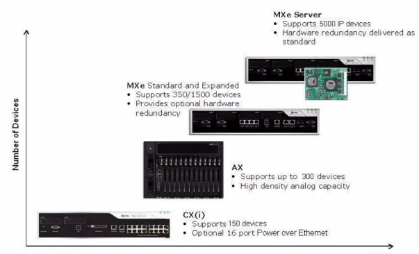
The 3300 ICP Controllers provide the voice, signaling, central processing, and communications resources for the system. Mitel offers a selection of five controllers and a server to meet the overall solution requirements of any site.
Figure 3: 3300 ICP Controllers — Scaling to Site Requirements
The controllers scale to meet the requirements of small to large scale sites.
• CX Controller – supports a maximum of 100 IP devices or a maximum of 150 On Premise Station (ONS) devices or a combined total of up to 150 devices.
• CXi Controller – the same capacity as the CX controller, but includes a 16-port powered Ethernet switch, router, and firewall. The CXi allows up to 16 IP devices to be connected directly to the powered ports.
• AX Controller – optimized for analog devices, this unit supports a maximum of 100 IP devices or a maximum of 288 ONS devices (or a combined maximum of 300 devices). Note that when installed in a low traffic environment (for example, Hospitality), the AX can support 288 analog sets and 288 IP sets, for a combined total of 576 devices. Up to 300 IP devices can be supported under low traffic conditions.
• MXe Controller (base configuration) – supports a maximum of 300 IP devices or 350 ONS devices (or a combined maximum of 350 IP/ONS devices).
• MXe Controller (expanded configuration) – supports a maximum 1400 IP devices or 1152 ONS (or a combined maximum of 1500 IP/ONS devices).
• MXe Server – supports up to 5,000 IP devices. This controller must be deployed in con-junction with other 3300 controllers because it is a dedicated call control engine for IP devices only. It connects over the LAN/WAN to other 3300 controllers which act as media gateways.
Controllers can be networked together over an IP infrastructure to deliver solutions for large or multi-site organizations.
Modules are field replaceable units (FRUs) that expand the functionality and capacity of the controller. Modules are installed in external and internal slots in the controller. The number of available slots depends on the controller model. Communication interface modules— such as the Dual FIM, Dual T1/E1 module, T1/E1 Combo Card, and Quad BRI Framer—are installed in slots that are accessible externally from the front or rear panel of the controllers.
The controllers have the following common physical features:
• External casing: All of the components may be stacked or rack-mounted (in a 19-inch rack). • Power supply: Each unit has its own standard male IEC AC input connector for power. • LEDs: All LEDs are located on the front or rear of the units for visual indication of circuit
status.
• LAN/WAN ports: RJ-45 connectors • Maintenance port: DB-9 (RS-232)
The following sections provide an overview of the controller variants. For detailed information on the controller capacities, refer to the controller configuration tables in the 3300 ICP Engineering Guidelines.
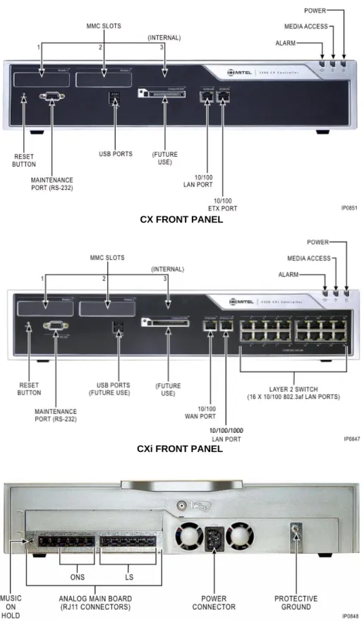
CX and CXi Controllers
The CX and CXi Controllers are shipped with an embedded Analog Main Board that supports 6 analog trunks and 4 analog extension ports. For solutions that require additional analog capacity, you can add an embedded Analog Option Module which provides an additional 6 trunks and 4 extensions, or an Analog Service Unit II which connects via a Quad Copper Interface Module (CIM).
The CX and CXi Controllers support:
• up to 100 IP devices, or up to 150 ONS devices, or a combination of up to 150 devices. • the Analog Main Board (AMB) - provides 6 analog trunks, 4 analog extension ports, Music
on Hold, and Paging
• the Analog Option Board (AOB) - provides an additional 6 analog trunks and 4 analog extension ports, Music on Hold, and Paging
• two externally accessible slots and one internal slot for optional modules • one 10/100 BaseT WAN port (RJ-45 connector)
• one 10/100/1000 BaseT LAN port (RJ-45 connector)
• sixteen 10/100 BaseT LAN ports connected to an internal Ethernet Layer 2 switch (CXi Controller only).
Optionally, you can install:
• a Quad or Dual DSP module for G.729a compression in the internal module slot • one DSP II for FAX Relay (T.38) and/or G.729 compression
• one or two T1/E1 Combo modules for digital trunking • one or two Quad BRI Framer modules for BRI trunks
• a Quad Copper Interface Module (CIM) for connection of up to three Analog Service Unit IIs (ASU IIs).
• an AOB for additional analog trunks and lines
• an APC-CX(i) processor in the CXi Controller to run applications (such as Teleworker, Mobile Extension, and Live Business Gateway).
Note: The CX and CXi Controllers do not support Network Service Units (NSUs) or peripheral cabinets.
Figure 4: CX/CXi Controllers
REAR PANEL CXi FRONT PANEL
AX Controller
The AX Controller provides support for IP devices and analog devices. It’s ideal where a high density of analog devices is required. It can be deployed as a standalone system or included in a network of systems to provide additional analog support.
The AX Controller supports a maximum of 288 IP devices, or a maximum of 288 ONS devices, or a combined maximum of 300 devices.
The AX Controller provides
• 12 line card slots to support analog phones and trunks. The following cards (all hot-swap-pable) are available:
- 16-port ONSp line card with protected ports - 24-port ONS line card
- 4 + 12 port combo card (4 analog trunks and 12 ONS ports) • two 10/100 BaseT Ethernet LAN ports (RJ-45 connector).
• one externally accessible expansion slot and one internal expansion slot for up to two of the following optional modules:
- Dual FIM (external)
- Quad DSP (external or internal) - Echo Canceller (external or internal) - Dual T1/E1 (external)
- T1/E1 Combo (external) - Quad BRI (external) - Quad CIM (external) - DSP II (internal or external). Optionally, you can install:
• 4 GByte flash card (required to support voice mail)
• second AC Power Supply Unit (PSU) for power redundancy • line cards.
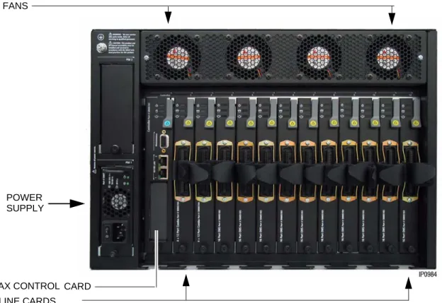
The AX Controller consists of a card chassis, power supply, controller card, and the optional line cards. The power supply, controller card, and line cards are accessed from the rear of the controller.
Note: When installed in a low traffic environment (for example, Hospitality), the AX can support 288 analog sets and 288 IP sets, for a combined total of 576 devices.
Figure 5: AX Controller Rear View
Figure 6: AX Controller Control Card FANS
POWER SUPPLY
AX CONTROL CARD LINE CARDS
MXe Controller
The MXe Controller is available in two capacities: standard and expanded. Both versions include an embedded Analog Main Board and redundant cooling fans.
The MXe Controller supports:
• up to 350 devices (combined IP/ONS) in the standard configuration
• up to 1400 IP devices and 1152 ONS (1500 combined IP/ONS) in the expanded configuration
• up to 1000 SIP devices/users.
The MXe can also host up to seven SX-200 Bays providing connectivity for 96 ONS or OPS devices per bay. Only BCCIII-equipped bays are supported. Trunk cards are not supported. The MXe Controller provides:
• two 10/100/1000 BaseT Ethernet LAN ports (RJ-45 connector) • one 10/100 BaseT Ethernet WAN port (RJ-45 connector)
• four externally accessible slots and two internal slots for optional modules • four CIM ports
• an Analog Main Board that provides 6 analog trunks and 4 analog extension ports • an alarm relay port.
Optionally, you can install
• MXe Expanded Processor Package to upgrade from standard capacity (350 devices de-vices and 64 E2T channels) to expanded capacity (1500 dede-vices and 128 or 192 E2T channels)
• two Quad DSP modules for G.729a compression
• two octal DSP II modules for G.729a compression and T.38 FAX support • up to four Dual FIMs for connecting NSUs, peripheral units, and bays • up to four Dual T1/E1 Framer modules
• up to three T1/E1 Combo modules • up to three Quad BRI Framer modules
• up to two Quad CIMs for connecting ASUs and bays
• power and disk drive redundancy with the addition of a RAID (Redundant Array of Inde-pendent Disks) controller, a second hard disk, and a second AC PSU.
Figure 7: MXe Controller FRONT PANEL
REAR PANEL - SINGLE HARD DRIVE
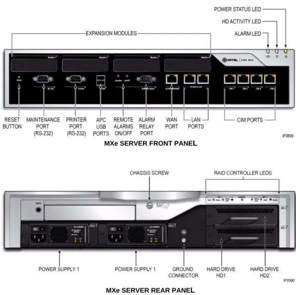
MXe Server
The MXe Server is purely a call control server for IP devices. It supports up to 5,000 IP devices and connects over the LAN/WAN to other 3300 ICP controllers to access digital trunks and analog devices. The MXe Server uses the same chassis and many of the same components as the MXe Controller, but it includes an additional application processor card (APC). The MXe Server is shipped with a RAID controller, dual hard drives, and dual power supplies.
The MXe Server provides the same call processing features and applications as the other controllers. However, the MXe Server runs with the Mitel Communications Director software. The Mitel Communications Director software is built on the Linux® operating system and runs
on the additional application processor card. The MXe Server supports:
• up to 5000 IP or SIP devices
• hardware redundancy as a standard feature — the MXe Server ships with a RAID controller, two hard disks, and redundant AC power supplies and cooling fans.
The MXe Server provides:
• expansion slots for up to two optional Quad DSP or octal DSP II MMCs • two 10/100/1000 BaseT Ethernet LAN ports (RJ-45 connector)
• one 10/100 BaseT Ethernet WAN port (RJ-45 connector)
• two 128-channel Echo Canceller MMCs (installed internally as standard components).
Note: Though the MXE Server does not directly support ONS devices or trunks, it can, however, connect to other 3300 ICPs that can provide ONS & Trunk connectivity.
Note: The four CIM ports are non-operational and the printer port is used only for communications with the APC.
Figure 8: MXe Server
MXe SERVER REAR PANEL
Analog Support
You can add analog support to a controller with an Analog Services Unit II, Analog Main Board, or Analog Options Board. The following table summarizes the analog support for each controller type:
Quad Copper Interface Module (CIM)
A Quad CIM MMC provides four CIM ports that allow you to connect ASU IIs to the following 3300 ICP controllers:
• CX and CXi Controllers support one Quad CIM module. Only the first three ports on the Quad CIM are functional, the fourth is not supported. Therefore, you can only connect up to three ASU IIs.
• AX Controller supports one Quad CIM module for the connection of up to four ASU IIs. • MXe Controller: This controller has four embedded CIM ports allowing the connection of
up to four ASU IIs. You can add up to two Quad CIM MMCs to increase the number of supported ASU IIs to 12.
• MXe Server: Although the MXe Server has 4 CIM ports, they are not operational. The LEDs will continue to flash, but they do not support ASU IIs.
The CIM ports require standard 8-pin modular jacks (RJ-45) consisting of 2 balanced signal pairs on Unshielded Twisted Pair (UTP) crossover cable. The CIM supports a distance of up to 100 feet or 30 meters between the controller and the ASU II.
Analog Services Unit II
The ASU II is a common platform to deliver analog trunks and extension services to all markets. It comprises a chassis with two card slots. Depending on how you configure the unit with line cards, the ASU II chassis can support up to 48 ONS phones and up to eight LS trunks. Two card variants (both hot-swappable) are available to support analog phones and trunks: • 24-port ONSp card provides 24 ONS lines for provisioning extensions outside the building.
The ports on this card are protected against surge and lightning.
Table 1: Analog Support
Controller Quad CIMs ASU IIs Analog Main Board
Analog Option Board
CX 1 3 with one Quad CIM installed 1 1 (optional)
CXi 1 3 with one Quad CIM installed 1 1 (optional)
AX 1 4 with one Quad CIM installed Not supported
MXe 2 4 without any Quad CIMs installed
8 with one Quad CIM installed 12 with two Quad CIMs installed
1 Not supported
• 12-port ONS/ 4-port LS Trunk Combination card provides analog line and trunk capability in a single card:
- 12 On-Premise Station (ONS) Lines for analog phones and four Loop Start (LS) trunks for analog connection to a central office. The ONS ports on this card are protected against lightning.
- Four System Fail Transfer (SFT) relays that provide direct connection between an analog telephone and a Loop Start trunk in the event of a system or power failure. - Custom Local Access Signaling Services (CLASS) is supported on the ONS circuits.
CLASS allows the 3300 ICP system to pass Calling Line ID digits and CLASS name information to display sets that support Caller ID functionality.
Any card can fit into either slot and the cards can be inserted while the unit is operational.
Analog Main Board/Analog Option Board
The MXe and CX/CXi Controllers support the Analog Main Board (AMB). Additionally, the CX/CXi can support the Analog Option Board (AOB).
The Analog Main Board supports: • six Loop Start (LS) trunks • four On-Premise (ONS) lines • two Power Fail Transfer (PFT) ports • one Music On Hold (MOH) circuit • one Loudspeaker Paging circuit.
The AOB provides the controller with an additional • six LS trunks
• four ONS lines
• one Music On Hold (MOH) circuit • one Loudspeaker Paging circuit.
Custom Local Area Signaling Services (CLASS) is supported on embedded LS trunks and ONS lines. CLASS allows the 3300 ICP system to pass Calling Line ID digits and CLASS name information to display sets that support Caller ID functionality.
Note: ASU IIs support DTMF telephones only; pulse or rotary dial phones are not supported.
Digital Trunk Support: Units and Modules
The Network Service Units and digital trunk modules provide connectivity to digital trunks for public or private networks. The following table summarizes the digital trunk support for the controllers.
Dual Fiber Interface Module (FIM)
The Dual Fiber Interface Module (FIM) converts:
• optical signals received over a fiber optic cable to electrical signals • electrical to optical signals for transmission over the cable.
The Dual FIM module allows you to connect • NSUs to the MXe Controller and AX Controller
• Peripheral Cabinets to the MXe Controller (the AX Controllers do not support Peripheral Cabinets).
Each Dual FIM allows you to connect up to two NSUs or two Peripheral Cabinets to the controller. The NSUs or Peripheral Cabinets connect to the controllers via fiber optic cabling. The fiber optic cabling allows units or cabinets to be located up to 14 km from the controller.
Universal Network Services Unit
The Universal NSU provides T1 or E1 connectivity and supports up to two T1 or E1 links per unit. The protocols supported by the T1 interfaces are
• T1 CAS - Digital E&M, Digital CO, Digital DID
• T1 CCS - Primary Rate ISDN (4ESS, DMS 100, DMS 250, NI-2, NI-2-5ESS, NI-2-GTD5, IDA-P), XNET over PRI, QSIG, and MSDN/DPNSS.
Table 2: Digital Trunk Support
Controller Available External Slots Dual FIMs Universal Network Services Units R2 Network Services Units Dual T1/E1 Framer T1/E1 Combo Modules Quad Basic Rate Interface Framer Modules
CX 2 Not supported maximum of any 2 modules
CXi 2 Not supported maximum of any 2 modules
AX 1 1 Not supported 2 maximum of any 1 module
MXe 4 4 8 NSUs (any type) 4 maximum of any 3 modules
MXe Server 4 Not Supported
The protocols supported by the E1 interface are:
• Q.Sig, Euro ISDN, XNET over PRI, DASS II, and MSDN/DPNSS
The Universal NSU connects to a 3300 ICP Controller through a fiber cable. Additional digital trunk capacity can be added to the 3300 ICP by chaining two NSUs together via the Copper Interface Module (CIM) connection, on the back of the NSU.
Figure 9: Universal Network Services Unit
R2 Network Services Unit
R2 is a protocol converter that allows the R2 NSU to access an R2 National Public Switched Telephone Network (PSTN) using MF-R2 digital trunk signaling. The 3300 Controller also receives and processes Calling Line Identification (CLI) and allows the information to be displayed on the user's telephone display screen.
The R2 NSU supports the CCITT Blue Book, Volume VI, Fascicle VI.4, Specifications of Signaling System R2, Recommendations Q.440 to Q.490 (with the exception of Echo Suppression (Q.479), Test Calls (Q.490) and international signals).
The R2 NSU converts the following:
• Incoming MF-R2 signals from the PSTN into Digital Private Network Signaling System (DPNSS) signals for the system
• Outgoing DPNSS signals from the system into MF-R2 signals for the PSTN.
Figure 10: R2 Network Services Unit
Note: Both interfaces must be either T1 or E1 and both must be T1 CAS or DPNSS or DASSII or PRI/QSIG. For T1/D4 and PRI/QSIG, you can mix the variants on each interface. For example, on T1/D4 you can mix the types on each interface (DID, CO, E&M) and for PRI/QSIG you can run different protocols for the signalling types.
Dual T1/E1 Framer Module
The Dual T1/E1 Framer module is a digital trunk interface that supports the direct connection of ISDN-PRI, T1/D4, QSIG, MSDN/DPNSS, and IDA-P trunks to the controller. This module has two ports supporting two digital links. Each port can support a different protocol.
T1 interfaces (1.544 Mbits/sec) support:
• ISDN PRI and QSIG links composed of 23 B-channels (bearer channels) for voice or data plus one D-channel (data channel) for signaling
• T1/D4 links composed of 24 B-channels • IDA-P.
E1 interfaces (2.048Mbits/sec) support ISDN PRI and QSIG links composed of 30 B-channels plus one D-channel.
T1/E1 Combo Module
The T1/E1 Combo Module combines trunk support, DSP functionality, and resiliency support in a single module. T1/E1 trunk resiliency is designed for businesses where resilience is critical, but where only a single digital link to the PSTN is required. If a site's primary controller fails, this feature automatically transfers the support for the T1/E1 trunk from the T1/E1 Combo Module in the primary controller to a T1/E1 Module in the secondary controller.
The digital trunk port can be configured as a T1 interface (1.544 Mbps) that provides 24 B-channels for T1/D4 or an E1 interface (2.0 Mbps) that provides 30 B-channels for E1. The DSP provides resources for voice echo cancellation. Embedded PRI is available for the 3300 ICP via the T1/E1 module.
Quad Basic Rate Interface (BRI) Framer Module
The Quad Basic Rate Interface (BRI) Framer Module is a digital trunk interface that supports the direct connection of BRI trunks to the controller eliminating the need for a BRI NSU. The BRI Framer Module has four ports supporting four digital links. Each port may be configured as either of the following:
• T (trunk) interface for links from a BRI Central Office.
• S (subscriber) interface for connecting up to eight BRI devices to the controller.
The Quad BRI Framer is supported in Europe, Middle East, Africa, and Australia.
Note: The D-channel backup, NFAS, and min/max capability features are not supported for embedded ISDN PRI links.
Note: The CX/CXi Controller and MXe Server do not support the Dual T1/E1 Module.
Note: S interfaces support only basic call features such as calling number display for BRI devices. BRI call handling such as Hold or Transfer is not supported. BRI devices are not line powered from the Quad BRI Framer. The U interfaces are not supported.
SX-200 Bay Support
SX-200 Cabinet
The MXe Controller can support up to seven SX-200 Bay cabinets. The SX-200 Bay cabinet holds up to 12 card slots: eight slots support line (ONS, OPS or DNI) cards, and four slots support the control cards and the FIM or CIM carrier cards. The bays are connected to a 3300 ICP using FIM or CIM cables.
SX-200 Peripheral Cards
The SX-200 Bay cabinet consists of Peripheral Interface Cards. The peripheral interface cards connect peripheral devices (such as SUPERSET™ telephones) to the system. They are located in slots 1 through 8. They include
• Digital Line Card
• On-Premise (ONS) Line Card • Off-Premise (OPS) Line Card.
Each ONS port requires an ONS licence on the 3300 ICP, which is counted against the 3300 ICP software device limits.
Digital Network Interface Line Card
The Digital Network Interface (DNI) line card provides an interface from the system to Mitel SUPERSET telephones and SUPERCONSOLE 1000 attendant consoles.
The DNI line card supports voice/data transmission at the rate of 128 kb/s (64 kb/s on each of two voice channels) and 16 kb/s on one signaling channel over a loop length of up to 3280 ft (1000 meters), using 24 - 26 AWG wire (25 - 27 IWG). The DNI line card provides full duplex digital transmission of both voice and data.
ONS/CLASS Line Card (North America Only)
The ONS (On-Premise)/CLASS (Custom Local Area Signaling Service) line card has 12 circuits that connect up to 12 standard telephones with line loop resistance, usually not exceeding 600 ohms including the telephone. As such, the card is used to connect internal telephone extensions close to the system. It also supports modems and fax machines. These cards install in any peripheral interface card slot and are hot-swappable.
Note: SX-200 Bays are supported by MXe controllers only.
Note: SX-200 Bays are not supported in Europe.
OPS Line Card (North America Only)
The OPS Line Card contains six off-premises line circuits. An Off-Premises (OPS) line circuit is used where the line goes outside the building that houses the PBX and the line may be exposed to extraneous high voltages or induced currents.
Peripheral Interface Module Carrier Card
The Peripheral Interface Module Carrier Card (PIMCC) holds a FIM II or CIM to provide the fiber or copper interface between a peripheral cabinet and the 3300 ICP. The FIM II and CIM interface modules on the BCC III also provide the connectivity needed to the 3300 ICP, making the PIMCC dispensable.
The Peripheral Interface Module Carrier card plugs into slot 12 of an SX-200 cabinet.
System Resources: Processors, Cards, and Modules
This section describes the cards and modules that support the system. To meet site requirements, you may need to add additional system resources to the controller. When planning a site, refer to the Configuration Tables in the Engineering Guidelines to determine if additional system resources, such as compression, echo cancellation, or Ethernet-to-TDM (E2T) channels are required.
Processors (E2T/RTC)
The CX/CX(i), AX, and standard MXe Controllers use a single processor to perform the Real Time Controller (RTC) functions and the Ethernet-to-TDM (E2T) functions. The expanded MXe Controller and MXe Server have separate processors for these functions.
The E2T converts voice streaming between Internet Protocol and Time Division Multiplexing (TDM) signals. The RTC runs the call control for the controller and acts as a gateway for the IP signals/packets.
Digital Signal Processor Modules
The Digital Signal Processor (DSP) Modules perform basic telephony and compression functions including:
• Conferencing
• Voice Mail playout and recording
• Call Progression tone generation and detection • Auto-attendant support
• G.729a compression (for IP trunking and wireless phones)
• FAX over IP (T.38) and additional G.729a compression (provided by the high-density DSP II MMC)
• conferencing (at startup)
• voice mail depending on the number of ports programmed in the customer database (at startup)
• tone generation and detection as required by traffic conditions (on a per call basis). • auto-attendant features.
You can add additional DSP resources to a controller by adding a Quad DSP module, a Dual DSP Module, or a DSP II Module. The Dual DSP module is only available for CX/CXi systems. Instructions on how to calculate system DSP requirements are provided in the 3300 ICP Technician’s Handbook.
Echo Cancellation Module
The Echo Canceller (EC) module provides echo cancellation on E2T channels. Each bi-directional E2T channel requires one bi-directional EC channel. The EC module provides 128 EC channels.
Applications Support
Application Processor Card - MXe Server
The Application Processor Card (APC-MXe) is an embedded PC card that is standard in the MXe Server. It runs the Mitel Communications Director call control software. In the MXe Server, the RTC performs the role of Media Server, with the APC-MXe performing call control functions. The Mitel Communications Director software and the controller software are pre-installed on the hard drives that are shipped with the MXe Server.
Application Processor Card - CX(i)
The APC-CX(i) is an optional card that you can install in the CX or CXi controller. The APC-CX(i) hosts the Mitel Standard Linux (MSL) Server software that supports applications such as: • Teleworker Solution - A secure teleworking solution for remote and home-based
employ-ees. This solution is supported on standard Mitel IP Phones.
• Mobile Extension - Enables users to "twin" their desk phone to another internal or external phone such as a cell phone.
• Live Business Gateway - enables communication between Microsoft® Office Communi-cator (MOC) and the 3300 ICP allowing MOC to take advantage of the basic and supplementary phone services offered by the 3300 ICP.
For information on how to program and use software blades and services, refer to the Mitel Standard Linux documentation at http://edocs.mitel.com.
Firewall (CXi, MXe and MXe Server only)
For security, the CXi and MXe can function as a firewall, dropping or rejecting unknown packets, allowing or disallowing IPSec and PPTP pass-through, and performing many-to-one NAT (IP masquerading).
By default, all inbound traffic is blocked by the firewall with the exception of packets for establishing PPTP VPN tunnels and ICMP requests to the IP address of the WAN interface.
3300 ICP Network Support
Voice Networking
Lines
The 3300 ICP supports the following internal voice connections:
• Ethernet connections are provided on the 3300 ICPs to connect the system to the custom-er's Ethernet LAN. IP phones communicate with the 3300 ICP over the Ethernet LAN. • On-Premises (ONS) lines are for industry-standard DTMF telephones. These lines are
supported by the ONSp line card in the ASU II and the AX Controller. ONSp card variants have "protected" ports that protect the circuitry against lightning and surges. ONS ports are also available on the Analog Main Board (AMB), or Analog Option Board (AOB).
• Digital Network Interface (DNI) lines provide an interface for Mitel legacy digital telephones and consoles. These lines are supported by the DNI Line card connected into the SX-200 Bay.
• On the client side, SIP phones are starting to proliferate across the full spectrum of telephony vendors.
Trunks
The system can connect to the Public Switched Telephone Network (PSTN) or to private networks over digital and analog trunks. The following digital links are supported:
• DS1 Links - The system supports the following protocols: D4, Q.Sig, MSDN/DPNSS, Pri-mary Rate ISDN (DM-250, DMS-100, Bellcore National ISDN, 4ESS, NI-2, 5ESS NI2), and XNET over PRI protocols. The system connects to DS1 links through the T1/E1 Modules or Universal NSU.
• E1 Links - The system supports DASS II, MSDN/DPNSS, Q.Sig, Primary Rate ISDN (Euro ISDN (CTR4)), and XNET over PRI protocols. The system connects to E1 links through the T1/E1 Modules or Universal NSU.
• R2 Links - The system supports the CCITT Blue Book, Volume VI, Fascicle VI.4, Specifi-cations of the Signaling System R2, and Recommendations Q.440 to Q.490 (with the exception of Echo Suppression (Q.479), Test Calls (Q.490) and international signals). The system connects to R2 links through the R2 NSU. Note that many countries use R2 signaling but do not adhere to the CCITT recommendations in their entirety. The 3300 ICP is com-pletely flexible and supports regional variations of the R2 protocol. Line signaling, tone interpretation, and timing parameters for the converter can be adapted to suit any national or regional requirement. For example:
- Line signaling features allow you to program up to four bits to define the incoming and outgoing patterns for line signals such as Idle and Answer
- Register signaling features allow you to program the type of address signaling
termination (signaled or timed) and whether signaling should be fully-compelled or semi-compelled. These features allow the individual definition of each register signaling tone.
• PRI Links - The system supports DM-250, DMS-100, Bellcore National ISDN, 4ESS, NI-2, 5ESS NI2, NI13, Euro ISDN (CTR4) protocols, and IDA-P PRI protocol used in Hong Kong. The system connects to PRI links through the T1/E1 Modules or Universal NSU.
• BRI Links - The system supports Euro ISDN 2B + D, Basic Rate Interface, or the North American ISDN-1 and ISDN-2 protocols. The system connects to BRI links through BRI NSUs or through Quad BRI Framer modules:
- The BRI NSU provides connectivity for Basic Rate ISDN (BRI) transport of both data and voice traffic. This unit is available only in the North American variant, which supports U-Interface (user-side interface).
- The Quad BRI Framer module supports the S-Interface for the European market. This module is also supported in North America where the S-Interface is available. • SIP Trunks - Allow the 3300 ICP to connect to the Service Provider through the SIP protocol
over the IP network. Service Providers offer SIP trunks that provide flexible and cost-effec-tive WAN solutions for the 3300 ICP. The SIP Trunking solution provides basic feature functionality, billing capability, Emergency Services support, FAX support, and more. The following analog trunks are supported:
• Analog CO trunks - Loop start (LS) ports on the ASU II can be used to interface analog CO trunks with the system.
- LS CLASS trunks are available on the Analog Main Board, Analog Option Board, ASU II, and AX Controller line cards.
IP Networking
IP Networking provides customers with an option for networking systems together. Instead of leasing dedicated voice circuits, customers can route voice traffic over the existing LAN/WAN infrastructure. Mitel’s implementation of IP Networking can use
• a point-to-point topology to optimize network resources, or
• a fully meshed topology to maximize inter connectivity between systems.
Figure 12: IP Networking - Fully Meshed Topology
IP Networking supports the MSDN/DPNSS protocols over the IP infrastructure. Controllers can be clustered in a single location to provide greater resiliency than a single controller operating autonomously. Controllers that are geographically separated can be seamlessly networked to share information and services in a transparent and cost efficient manner. IP Networking can be used as the primary communication between controllers or as a backup to TDM networking. A 3300 ICP with IP Networking enabled can be configured to act as an IP Networking gateway for SX-2000 and SX-200® PBXs, or third-party PBXs.
Figure 13: 3300 ICP as Trunking Gateway for PBXs
The IP Networking feature supports G.711 and G.729a encoding. Connections with up to 999 other network nodes are supported. A total of 2000 IP network connections are supported from any one node and up to 200 connections can be defined between any two nodes. IP Networking is enabled via the IP Networking License. One license is required per controller in the network.
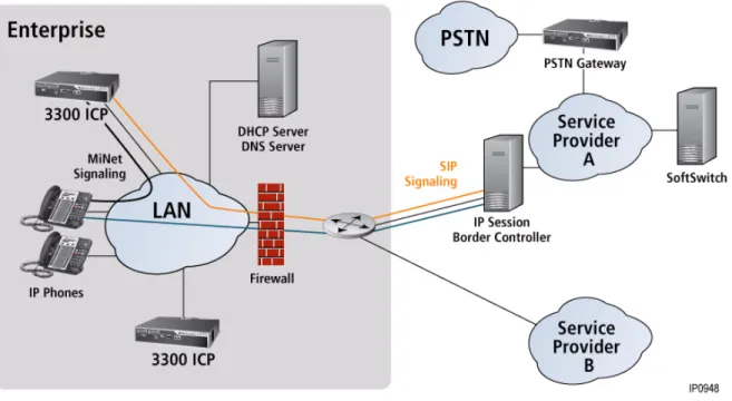
SIP Trunking
To manage costs within an organization, many businesses are considering replacing their traditional PSTN connections with new SIP services deployed by service providers. Mitel expects to see a proliferation of these services in the future and SIP trunking has the ability to support these new network services.
The 3300 ICP connects to the service provider’s network using the SIP protocol over the IP network. The SIP Trunking solution provides basic calling features, billing capability, Emergency Services support, FAX support, and more.
Figure 14: SIP Trunking
9-1-1
SIP Trunking supports 9-1-1 emergency service. The SIP service provider can be chosen as the outgoing emergency route.Caller’s Emergency Service Identification (CESID) information must also be programmed.
DNS Support
Communication between SIP Service Providers and the 3300 ICP can be configured to use either Fully Qualified Domain Names (FQDN) or IP Addresses.
Configurable Real-time Transport Protocol (RTP) Packetization
3300 administrators can configure the voice stream packet rate for SIP trunks to their service provider’s, choosing a rate between 10ms to 80ms (with 10ms increments). IP sets supporting this feature include the 5302, 5304, 5212, 5224, 5235, 5312, 5324, 5330, 5340,
Billing and SMDR
The Service Provider bills calls based on the peer connection to the 3300 ICP. The 3300 ICP records are created with a special SMDR tag entered in the SIP Peer Profile form. An SMDR tag can be enabled for outgoing and incoming calls.
Malicious Call Trace
For incoming SIP calls that are tagged for Malicious Call, the 3300 records the Media IP address and port used remotely. As well, the SIP signalling information is captured. This information cannot be sent to the SIP Service Provider, but the information is recorded if needed.
Note: Malicious Call SMDR records are logged on the 3300 ICP. SIP endpoints cannot invoke Malicious Call Trace, but it is recommended that SMDR be enabled for SIP devices and gateways.
FAX Support
You can configure the 3300 ICP network to allow facsimile to be sent over the IP network using G.711 pass-through or IP network using FAX Relay (T.38).
Real-time, Group 3 facsimile (FAX) communication over IP networks using FAX Relay (T.38 standard protocol) allows you to transmit and receive facsimile over IP trunks between FAX machines on 3300 ICP (Release 9.0 or later) systems.
FAX Over IP Using T.38 FoIP
FAX Relay (T.38) is the preferred method because the quality and performance of FAX transmission is superior to that of the G.711 pass though method, especially over WAN links. The LAN and WAN do not have to be engineered specifically to support this method of FAX transmission.
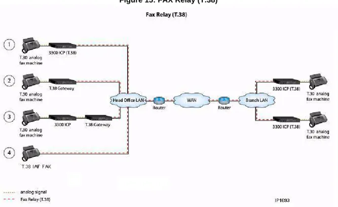
The following diagram illustrates four different ways that FAX Relay (T.38) can be employed to support fax transmission:
• FAX machine connected to a T.38 protocol enabled 3300 ICP • FAX call transferred by 3300 ICP to a T.38 protocol enabled gateway • FAX machine connected directly to a T.38 protocol enabled gateway • Internet Aware FAX (IAF) machine with built in T.38 gateway functionality
Figure 15: FAX Relay (T.38)
FAX Over IP Network Using G.711 Pass-Through
This method uses T.30 protocol with G.711 pass through to send FAX over IP trunks using the LAN and WAN. The 3300 ICP systems in the network must be running Release 7.0 or later.
Figure 16: G.711 Pass Through.
This method has the following advantages:
• allows you to send faxes between 3300 ICP systems over the IP network
• reduces the cost of sending long-distance faxes because the data is sent over the IP network and not the PSTN
However, this method has the following disadvantages:
• LAN and WAN must be engineered to meet the LAN quality guidelines specified in the 3300 ICP Engineering Guidelines.
• Voice packets carrying fax on the network cannot be compressed.
• Quality and performance of fax transmission using G.711 pass through is inferior to the quality and performance provided by FAX Relay (T.38) protocol, especially over WAN links because the likelihood of experiencing network issues is higher.
Compression
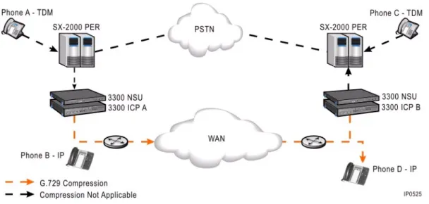
Optimization of bandwidth is a key requirement in a VoIP system. In order to meet this requirement, the 3300 ICP supports G.729a voice compression. G.729a compression reduces the bandwidth required for a call from 64 kbps to 8 kbps plus packet overhead. By using voice compression across the LAN/WAN infrastructure, customers can ensure that they are able to optimize their bandwidth usage for voice calls. The mechanism for managing this feature is based on a zone concept. Groups of devices on the 3300 ICP can be placed in a zone so that calls between zones can be compressed while calls within the same zone are not. Zones can be defined within a controller's LAN infrastructure, between remote IP devices and the controller and across the WAN for multiple controller networks.
Most Mitel IP phones inherently support G.729a voice compression. Calls between IP Phones on the LAN/WAN infrastructure can thus be compressed to G.729a as required. For example, a call between IP Phone B and IP Phone D (over the LAN or WAN) can be compressed without system compression resources.
G.729a compression is also supported for calls that have TDM (Digital or Analog) endpoints that cross the LAN/WAN infrastructure. For example, a call from TDM phone A to IP Phone D can be compressed using compression resources in controller A to compress the LAN/WAN segment between Controller A and IP Phone D. The same compression occurs if TDM Phone A called TDM Phone C over the LAN/WAN, except that in this case compression resources would be required on both controllers.
Optional compression licenses and DSP modules can be purchased to enable TDM-to-IP compression on the 3300 ICP.
Figure 17: Voice Compression Between 3300 ICPs
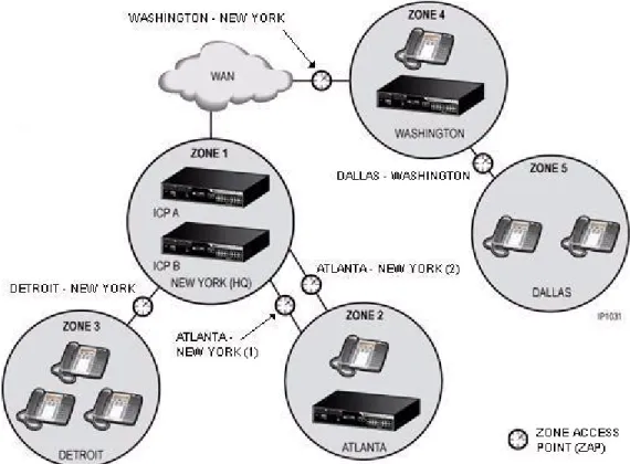
Bandwidth Management
For many customers, one of the key benefits of IP telephony is the opportunity to reduce costs and ongoing management by eliminating controller hardware at small remote sites. IP phones can simply be deployed across the WAN (or Internet using the Teleworker Solution) hosted off a centralized 3300 ICP controller with gateways for remote survivability. When remote sites are deployed, organizations must ensure that non-voice data has adequate bandwidth and that quality of voice can be preserved.
Where bandwidth between locations is restricted, you can reduce consumption by applying compression to the voice calls between IP Phones. Compression reduces the bandwidth demands of a standard voice call (G.711) by compressing the call using the G.729 codec. Compression is applied to calls between zones of IP Phones (see Compression on page 35 for details).
In addition, Mitel provides a bandwidth management feature that helps IT managers plan and justify network capacity expansions. The Bandwidth Management feature allows IT managers to perform the following tasks at predetermined zone access points (ZAPs) between the zones in the network:
• Measure and report consumed and available bandwidth
• Establish maintenance alarms when bandwidth consumption exceeds configured threshold levels
• Provide Call Admission Control, that is, reject new calls through a specific bottleneck point if the consumed bandwidth exceeds the maximum configured levels.
Figure 18: Bandwidth Management at Zone Access Points
Resiliency
Reliable communication is critical to businesses. Resiliency on the 3300 ICP increases communications reliability by maintaining calls in progress, handling new incoming and outgoing calls, and continuing to provide voice mail services in the event of a 3300 ICP or network failure. The Resiliency solution preserves system functionality in the event of network difficulties by distributing network intelligence throughout “resilient” clusters that anticipate and pro-actively mitigate system failure.
By taking advantage of IP-network characteristics of location independence, resiliency provides an extremely flexible solution to enhance system reliability. By using resources that are spread across the network, resiliency ensures that there is no single point of failure and that hardware resource utilization is optimized. Resiliency provides an obvious advantage over many other competing alternatives where solutions involve costly hardware redundancy for every controller (see See “Advantages Over Redundancy” on page 39.).
Resiliency is an IP-enabled capability that builds on existing 3300 ICP Voice Clustering (Portable Directory Number [PDN]), and call-routing principles. Existing clustering techniques are used to set up a cluster, which is then made resilient through the programming of boundary nodes, transit nodes, call routing ARS, and resilient devices. Resilient devices within the cluster are programmed on a primary and secondary controller. Should the primary controller experience a service outage, support for the resilient devices is automatically transferred to
the secondary controller. During the transfer of phone service between the primary and secondary controllers, calls in progress are maintained, ensuring that IP phone users are not affected by the controller outage. The figure below shows how a site can be configured with fully resilient devices. Node B is the secondary controller for the phones on Node A, and Node A is the secondary controller of the phones on Node B. Should either controller experience an outage, support for the phones is transferred to their respective secondary controller.
Figure 19: Resilient Configuration
As a further example, on a site where there is a MXe Server to support the users and an MXe Controller to act as a media gateway to the public telephone network, the IP phones can be supported by the MXe Server (primary controller) and have backup support available from the media gateway controller (secondary controller). Resiliency is supported for:
• IP Devices - A secondary ICP provides service to phones in the event of a failure on the primary ICP or in the event of a networking failure between the phone and the primary ICP. The secondary ICP directs phones to transfer back to the primary ICP once the failure is corrected.
• SIP Devices - A secondary ICP provides service to phones in the event of a failure on the primary ICP or in the event of a networking failure between the SIP endpoint and the primary ICP. SIP device resiliency is dependent on the particular SIP device deployed. SIP endpoint resiliency applies to Mitel’s 5300 series dual-mode IP Phones, IP DECT phones and other commercially available SIP devices.
• Trunks - A T1/E1 trunk connection can be critical to site operation if it is the only link to the network. If the primary ICP fails, a relay in the T1/E1 module physically transfers the trunk termination point to a T1/E1 module on the secondary ICP.
• Calls - Calls in progress over the IP infrastructure are maintained.
• Features - Most features are resilient and are available to a user while the user’s phone is in service on its secondary ICP. Also any programming changes that users make to their
phones while the phones are on the secondary controller are automatically updated on the primary controller after the phone re-homes to the primary controller.
• Voice mail - Embedded voice mail continues to be provided to a device when it moves to a secondary ICP during failure.
• Automatic Call Distribution - ACD Agent calls, agent status (for example, logged in, make busy, Do Not Disturb, and so forth) and Agent Skill Groups are resilient.
• Hunt groups- Resiliency is supported for voice, voice mail, or recorder hunt groups. The 3300 ICP supports only voice hunt groups. Currently, only NuPoint Messenger Release 10.0 and later supports voice mail or recorder group hunt group resiliency.
• Ring groups- Support for ring groups passes to the secondary controller if the primary fails. The Mitel system management tool, Enterprise Manager, or the System Administration Tool can be used to provision resilient users and devices on primary and secondary 3300 ICPs. The OPS Manager Moves, Adds and Changes work form populates 3300 ICP call control forms with resilient primary and secondary controller information.
Advantages Over Redundancy
Resiliency is less costly and more flexible than a redundant solution because it uses self-correction techniques that take advantage of the IP-network characteristics of location independence and network element distribution. While the redundancy model is highly effective and reliable, it is unnecessarily costly for some customers.
Distributed resilient networks offer the ability to route around failed or otherwise inaccessible portions of an IP network. This feature provides the following distinct advantages over the centralized 1+1 hardware requirements of a redundant solution:
• No single point of failure
• Lower hardware costs because of the efficient use of existing hardware.
Because any controller in the network can act as a secondary controller, Mitel Resiliency can be referred to as an "any +1" solution for system reliability. Rather than dedicating expensive, robust hardware to solving temporary and often infrequent system failures, Mitel Resiliency makes efficient use of a system’s existing capacity.
In resilient networks, a secondary controller is not limited to acting as a dedicated backup call-control host. In many cases, the secondary controller can also function as any one of the following:
• Full service controller (in a configuration where resiliency support is distributed among multiple controllers in the network)
• Group controller
• Wireless access controller • Call center controller • Video conference controller
• ΙP network gateway • PSTN gateway • Voice mail server.
Devices that Support Resiliency
The following Mitel IP devices support resiliency:
• All 5000 series, 5100 series, 5200 series, and 5300 series IP Phones • Navigator • 5550 IP Console • 5560 IPT • IP PKM 12 and IP PKM 48 • 5310 IP Conference Units • Teleworker.
Resilient clusters can contain pre-4.0 3300 ICPs and Mitel legacy SX-2000 PBXs. These devices cannot function as secondary controllers, but they can be part of a resilient solution as boundary nodes and transit nodes.
For detailed information on Resiliency, see the 3300 ICP Resiliency Guidelines.
Rapid Spanning Tree Protocol
Both Rapid Spanning Tree Protocol (RSTP) and Spanning Tree Protocol (STP) are supported on the CXi Controller, MXe Controller, AX Controller, and MXe Server:
• Spanning Tree Protocol (STP) is a Layer 2 Link Level protocol specified by the IEEE (802.1D) that runs on bridges and switches.
• Rapid Reconfiguration of Spanning Tree Protocol (RSTP) is also a Layer 2 Link Level protocol specified by the IEEE (802.1w) that runs on bridges and switches.
STP and RSTP serve the same purpose. The difference between the two protocols is how quickly the algorithms converge on a network. RSTP "reconverges" networks faster than STP. In an Ethernet network that is not using STP/RSTP, multiple active paths between devices are not allowed since multiple paths will cause network loops.
Network loops will cripple a network because a broadcast or multicast packet sent from Station “A” to Station “B” will be forwarded by Switch “B” to Station “B” and also back to Switch “A”, when Switch “A” receives the packet it will then forward the packet back to Switch “B” and the cycle will repeat for infinity causing a broadcast storm.
Note: Resiliency is an IP solution that does not support ONS, DNIC and older 4000-series IP Phones.