Volume Replicator
Administrator’s Guide
Windows Server 2003, Windows Server
2008
The software described in this book is furnished under a license agreement and may be used only in accordance with the terms of the agreement.
Product version: 5.1. Service Pack 2 Document version: 5.1 SP2
Legal Notice
Copyright © 2010 Symantec Corporation. All rights reserved.
Symantec, the Symantec Logo, Veritas and Veritas Storage Foundation are trademarks or registered trademarks of Symantec Corporation or its affiliates in the U.S. and other countries. Other names may be trademarks of their respective owners.
This Symantec product may contain third party software for which Symantec is required to provide attribution to the third party (“Third Party Programs”). Some of the Third Party Programs are available under open source or free software licenses. The License Agreement accompanying the Software does not alter any rights or obligations you may have under those open source or free software licenses. Please see the Third Party Legal Notice file accompanying this Symantec product for more information on the Third Party Programs.
The product described in this document is distributed under licenses restricting its use, copying, distribution, and decompilation/reverse engineering. No part of this document may be reproduced in any form by any means without prior written authorization of Symantec Corporation and its licensors, if any.
THE DOCUMENTATION IS PROVIDED "AS IS" AND ALL EXPRESS OR IMPLIED CONDITIONS, REPRESENTATIONS AND WARRANTIES, INCLUDING ANY IMPLIED WARRANTY OF MERCHANTABILITY, FITNESS FOR A PARTICULAR PURPOSE OR NON-INFRINGEMENT, ARE DISCLAIMED, EXCEPT TO THE EXTENT THAT SUCH DISCLAIMERS ARE HELD TO BE LEGALLY INVALID. SYMANTEC CORPORATION SHALL NOT BE LIABLE FOR INCIDENTAL OR CONSEQUENTIAL DAMAGES IN CONNECTION WITH THE FURNISHING, PERFORMANCE, OR USE OF THIS DOCUMENTATION. THE INFORMATION CONTAINED IN THIS DOCUMENTATION IS SUBJECT TO CHANGE WITHOUT NOTICE.
The Licensed Software and Documentation are deemed to be commercial computer software as defined in FAR 12.212 and subject to restricted rights as defined in FAR Section 52.227-19 "Commercial Computer Software - Restricted Rights" and DFARS 227.7202, "Rights in Commercial Computer Software or Commercial Computer Software Documentation", as applicable, and any successor regulations. Any use, modification, reproduction release, performance, display or disclosure of the Licensed Software and Documentation by the U.S. Government shall be solely in accordance with the terms of this Agreement.
Symantec Corporation 350 Ellis Street
Mountain View, CA 94043 http://www.symantec.com
Symantec Technical Support maintains support centers globally. Technical Support’s primary role is to respond to specific queries about product features and functionality. The Technical Support group also creates content for our online Knowledge Base. The Technical Support group works collaboratively with the other functional areas within Symantec to answer your questions in a timely fashion. For example, the Technical Support group works with Product Engineering and Symantec Security Response to provide alerting services and virus definition updates.
Symantec’s support offerings include the following:
■ A range of support options that give you the flexibility to select the right amount of service for any size organization
■ Telephone and/or web-based support that provides rapid response and up-to-the-minute information
■ Upgrade assurance that delivers automatic software upgrades protection ■ Global support purchased on a regional business hours or 24 hours a day, 7
days a week basis
■ Premium service offerings that include Account Management Services For information about Symantec’s support offerings, you can visit our web site at the following URL:
www.symantec.com/business/support/index.jsp
All support services will be delivered in accordance with your support agreement and the then-current enterprise technical support policy.
Contacting Technical Support
Customers with a current support agreement may access Technical Support information at the following URL:
www.symantec.com/business/support/contact_techsupp_static.jsp
Before contacting Technical Support, make sure you have satisfied the system requirements that are listed in your product documentation. Also, you should be at the computer on which the problem occurred, in case it is necessary to replicate the problem.
When you contact Technical Support, please have the following information available:
■ Product release level ■ Hardware information
■ Available memory, disk space, and NIC information ■ Operating system
■ Version and patch level ■ Network topology
■ Recent software configuration changes and network changes
Licensing and registration
If your Symantec product requires registration or a license key, access our technical support web page at the following URL:
www.symantec.com/business/support/
Customer service
Customer service information is available at the following URL: www.symantec.com/business/support/
Customer Service is available to assist with non-technical questions, such as the following types of issues:
■ Questions regarding product licensing or serialization
■ Product registration updates, such as address or name changes
■ General product information (features, language availability, local dealers) ■ Latest information about product updates and upgrades
■ Information about upgrade assurance and support contracts ■ Information about the Symantec Buying Programs
■ Advice about Symantec's technical support options ■ Nontechnical presales questions
Support agreement resources
If you want to contact Symantec regarding an existing support agreement, please contact the support agreement administration team for your region as follows: Asia-Pacific and Japan [email protected] Europe, Middle-East, and Africa [email protected]
Chapter 1
Understanding Veritas Volume Replicator
About Veritas Volume Replicator ...17
Feature highlights of VVR ...17
Basic VVR terms ...18
Primary and secondary host ...19
Write-order fidelity ...19
Consistent data versus up-to-date data ...19
Heartbeat protocol ...20
Building blocks of VVR (volume replicator objects) ...21
Replicated Volume Group ...21
Replicator Log volume ...22
Replication Link—RLINK ...23
Replicated Data Set ...23
Data Change Map ...24
Understanding replication in the VVR environment ...26
VVR at the primary ...26
VVR at the secondary ...27
How replication happens in the VVR environment ...28
Modes of replication ...28
Synchronous mode of replication ...29
Understanding data flow in VVR synchronous mode ...30
Asynchronous mode of replication ...32
Understanding data flow in VVR asynchronous mode ...33
Synchronous override mode ...34
Understanding data flow in an RDS that contains multiple secondary hosts ...34
Managing data during failure and recovery ...36
Preventing data loss ...36
Maintaining data consistency ...37
Detecting host and connection failures ...37
Securing VVR ...38
Chapter 2
Replication concepts
Using VVR as a disaster recovery tool ...39Taking over the primary role ... 40
Performing takeover with fast-failback ... 40
Understanding how VVR logs writes to the Replicator Log ... 41
Sizing the Replicator Log ... 43
Understanding replication settings for a secondary ... 45
Mode of replication—synchronous attribute ... 46
Using the available bandwidth effectively ... 47
Choosing the network protocol ... 47
Measures to protect log overflow and replication latency ... 48
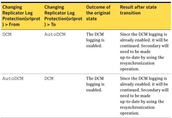
Replicator Log overflow protection—srlprot attribute ... 48
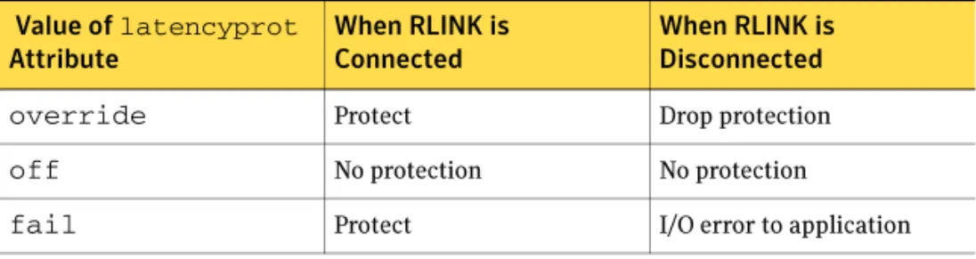
Latency protection—latencyprot attribute ... 54
Pausing replication ... 56
Pausing replication from the primary host ... 56
Pausing replication from the secondary host ... 56
Applications of the pause feature ... 57
Understanding checkpoints ... 57
Synchronizing the secondary ... 59
Using automatic synchronization ... 59
Using incremental synchronization after log overflow ... 60
Using backup and checkpoint ... 61
Understanding VVR support for Flashsnap ... 61
About the snapshot operation ... 64
About the snapback operation ... 65
About Synchronized Snapshots ... 66
How VVR creates synchronized snapshots ... 66
Understanding Bunker replication ... 67
About Bunker replication ... 68
Advantages of Bunker replication ... 68
How Bunker replication differs from normal replication ... 68
Bunker node workflow during normal operations ... 69
Using the Bunker node for disaster recovery ... 70
Understanding VVR TCP multi-connection ... 72
Advantages of TCP multi-connection ... 72
About VVR compression ... 72
General functionality constraints for VVR compression ... 73
About VVR memory monitoring and control support ... 73
Advantages of VVR memory monitoring ... 73
General functionality constraints for VVR Memory Tuning ... 74
About VVR Graphs ... 74
Chapter 3
VVR installation and security requirements
About installing VVR and security requirements ... 75Initial installation ...76
Licensing information ...76
Before installing VVR ...76
Installing VVR ...77
Verifying the VVR installation ...77
User access rights ...78
Security considerations for VVR ...78
Validating the user access rights ...78
About specifying network ports for replication ...84
Enabling NAT support for VVR ...84
Chapter 4
Setting up replication
About setting up replication ...87Best practices for setting up replication ...88
Setting up replication using the setup replicated data set wizard ...89
Prerequisites for setting up the RDS ...90
Setting up the Bunker RVG for replication ...105
Prerequisites for setting up Bunker RVG ...105
Best practices for creating the Bunker RVG ...105
Adding the Bunker RVG to the RDS ...106
Chapter 5
Using the VEA Console for VVR Operations
About performing VVR operations in the VEA console ...111Features of VEA console ...111
Launching the VEA console ...112
Managing connections ...113
Connecting to a host ...114
Disconnecting from a host ...116
Reconnecting hosts at startup ...116
Using history to view recent connections ...116
Managing favorites ...117
Adding a host to the favorites ...117
Removing a host from the favorites ...117
Switching connections ...117
Layout of the VEA console ...118
Performing tasks related to views ...118
Selecting objects ...119
Left pane or navigation view (tree view) ...120
Right pane or details view (tabular view) ...120
Status pane ...121
URL bar ...122
Menu bar and tool bar ... 124
Accessing the VVR options ... 125
Menu bar options ... 125
Exiting the VEA client ... 127
Chapter 6
Monitoring replication
About monitoring replication ... 129Interpreting the information in the VVR views ... 129
Viewing all the RDSs on the host ... 130
Viewing RDS information ... 131
Viewing information about the primary RVG ... 139
Viewing information about the secondary RVG ... 142
Viewing information about the primary data volume ... 145
Viewing the Replicator Log volume information ... 147
Viewing information about the secondary data volume ... 148
Monitoring replication ... 149
Displaying the monitor view ... 149
Specifying preferences for the monitor view ... 150
Interpreting the information in the monitor view ... 152
Checking replication performance using vxrlink stats ... 157
Identifying the most up-to-date secondary ... 159
Analyzing VVR performance ... 159
Monitoring alerts to interpret error conditions ... 162
Handling VVR events ... 162
Chapter 7
Administering VVR
About administering VVR ... 165Modifying the configuration ... 165
Adding volumes ... 166
Adding a secondary host ... 170
Administering the RVG ... 181
Enabling or disabling data access to the RVG data volumes ... 181
Expanding the data volumes ... 182
Expanding the Replicator Log ... 183
Shrinking the data volumes ... 184
Adding or removing the DCM logs from the data volumes ... 184
Resynchronizing the secondary hosts ... 185
Associating or dissociating the Replicator Log volume ... 186
Administering replication ... 187
Disabling the SwiftSync feature ... 188
Starting replication ... 189
Changing replication settings ...190
Managing checkpoints ...194
Pausing replication ...196
Converting the primary to a secondary ...198
Migrating the primary role ...199
Creating snapshots for the data volumes ...200
Creating synchronized snapshots using the VSS Snapshot Wizard ..202
Recovering the RVG ...213
Restoring the secondary ...213
Administering Bunker replication ...214
Stopping replication ...215
Pausing secondary ...215
Changing replication settings ...215
Associating or Dissociating the Replicator Log ...215
Activate Bunker ...217
Deleting the Bunker secondary ...217
Performing disaster recovery operation ...218
Using the Bunker node to update the secondary ...219
Resynchronizing the original primary when it becomes available ....219
Updating the secondary from the Bunker ...220
Taking over the primary role ...221
Performing takeover in a multiple Bunker setup ...224
Deleting VVR objects ...224
Removing data volumes ...225
Deleting the replicated data set ...226
Deleting the Primary RVG ...226
Deleting the Secondary RVG ...227
Accessing data on secondary host ...227
Creating a mirror break-off ...228
Creating snapshots ...228
Performing automated system recovery (ASR) ...229
Automated system recovery (ASR) overview ...229
VVR support for ASR ...230
ASR recovery process ...231
Microsoft Cluster recovery ...232
Alternative methods to synchronize the secondary faster ...233
Method 1: Moving the secondary RVG disk group on to a spare server within the same LAN as the primary ...234
Method 2: Using snapshots for synchronizing the secondary data volumes ...235
Method 3: Using mirrored plexes ...238
Obtaining statistical information through VVR Graph ...240
Viewing statistical information using VVR Graph ... 242
Chapter 8
Using the command line interface
About using the command line interface ... 247Conventions for command line syntax ... 249
Administering the RDS using the vxrds command ... 250
Activating the Bunker RVG ... 254
Creating and adding a secondary RVG ... 254
Adding an existing volume to the RDS ... 255
Adding a Bunker node ... 255
Changing the host name or IP ... 256
Creating the primary RVG ... 257
Deactivating the Bunker RVG ... 258
Deleting the Bunker node ... 258
Deleting the secondary ... 258
Deleting the primary ... 259
Dissociating data volumes ... 259
Resynchronizing a failed primary with the new primary ... 260
Converting a primary to a secondary ... 261
Migrating the primary to a secondary ... 261
Pausing replication ... 262
Displaying the RDS ... 263
Resizing the data volumes ... 263
Growing the Replicator Log volume ... 264
Resuming replication after pausing ... 265
Resynchronizing the secondary ... 265
Setting replication attributes ... 265
Starting replication ... 268
Stopping replication ... 270
Taking over the primary role ... 270
Performing RLINK Operations using the vxrlink command ... 270
Associating a secondary ... 274
Attaching a secondary ... 274
Displaying the list of secondary checkpoints ... 275
Deleting the secondary checkpoint ... 275
Detaching an RLINK ... 275
Dissociating an RLINK ... 275
Creating new RLINK ... 276
Pausing the RLINK ... 278
Recovering the RLINK ... 279
Restoring the RLINK ... 279
Resuming the RLINK ... 280
Setting the RLINK attributes ...280
Displaying the network statistics for the RLINK ...282
Displaying the RLINK status ...285
Identifying the most up-to-date secondary ...287
Verifying the RLINK ...288
Starting the Historic Bandwidth Data Collection using the CLI ...289
Stopping the Historic Bandwidth Data Collection using the CLI ...290
Administering the RVGs using the vxrvg command ...290
Adding DCM log ...294
Associating the Replicator Log volume to an RVG ...295
Associating data volume with the RVG ...295
Ending checkpoint ...295
Starting the checkpoint ...295
Deleting the RVG checkpoint ...296
Displaying RVG checkpoints ...297
Dissociating volumes from RVG ...297
Dismounting data volumes ...297
Creating new RVG ...298
Converting a secondary RVG to primary RVG ...299
Converting a primary RVG to secondary RVG ...300
Recovering the RVG ...300
Removing an RVG ...301
Resynchronizing the RVG ...301
Setting RVG attributes ...302
Creating snapshots for data volumes in an RVG ...302
Reattaching the snapshot volumes back to the data volumes in an RVG ...303
Enabling data access (Starting the RVG) ...304
Generating application statistics ...304
Disabling data access (Stopping the RVG) ...305
Displaying information using the vxprint command ...305
Displaying a specific RLINK ...307
Interpreting RLINK flag settings ...307
Displaying an individual RVG ...309
Displaying an individual data volume or Replicator Log ...310
Creating snapshots using the vxsnap command ...311
Preparing volumes for snapshots ...314
Creating Synchronized Snapshots ...314
Reattaching the Snapshots ...316
Displaying memory statistics using the vxmemstat command ...317
Analyzing the increase and decrease action of reduction factor ...318
Administering replicated volumes using the vxvol command ...320
Associating a volume to an RVG as a Replicator Log ... 322
Dissociating a volume from an RVG ... 323
Displaying and changing replication ports using the vrport command ... 324
Displaying or setting ports for replicating data ... 325
Displaying or setting ports for heartbeats ... 325
Displaying or setting ports for vradmind ... 326
Displaying or setting ports for vxrsync ... 327
Administering the RVG using the vxedit ... 327
Deleting the VVR objects ... 329
Setting the attributes ... 329
Administering the RVG using the vxassist command ... 331
Adding a DCM log ... 332
Growing the volumes ... 333
Removing a DCM log ... 333
Tuning VVR ... 334
Displaying the tunable values ... 338
Setting the tunable values ... 339
Examples: Using the command line ... 340
Sample setup ... 340
Example 1: Setting up replication using the command line interface 341 Example 2: Setting up Bunker replication ... 342
Example 3: Using Bunker node for disaster recovery ... 343
Example 4: Using synchronized snasphots to restore data ... 347
Chapter 9
Configuring VVR in a VCS environment
About configuring VVR in a VCS environment ... 351Components of a VCS cluster ... 352
Resources ... 352
Attributes ... 352
Service groups ... 353
Illustrating a highly available VVR setup ... 354
List of agents for VVR ... 355
Installation information ... 355
How the agents work ... 355
VvrRvg agent ... 356
RVGPrimary agent ... 361
Configuring the agents ... 370
Taking the application group offline on Secondary ... 373
Setting up replication using a virtual IP address ... 373
Changing the Primary and Secondary IP ... 373
Creating RLINKs between each pair of Secondary hosts ... 374
Creating the replication service group ... 375
Adding a new RVG resource to an existing
replication Service group ...378
Modifying an existing resource in the replication service group ...381
Chapter 10
Configuring VVR with Hyper-V
Implementing VVR replication on Hyper-V with Microsoft Failover Cluster 385 Prerequisites for setting up VVR with Hyper-V ...385Configuring a virtual machine group and resource dependencies ....386
Configuring replication for the virtual machine ...386
Setup 1: Replicating the System as well as Data disks ...387
Setup 2: Replicating the Data disks ...387
Recommendations and workarounds ...388
Chapter 11
Advanced settings in VVR
About using the advanced settings in VVR ...389Tuning the VVR memory parameters ...389
Understanding the concept of a buffer space ...389
Modifying the tunable values ...392
Understanding IBC messaging ...392
Features of the IBC messaging ...392
Application of IBC messaging ...393
IBC messaging commands ...393
Example: Using IBC messaging facility to take snapshots ...400
Chapter 12
Troubleshooting VVR
About troubleshooting VVR ...403Recommendations and checks ...403
Encrypted files on replicated volumes ...404
Selecting the mode of replication ...404
VVR issues when Norton Antivirus scan is performed ...404
Monitor view does not display the RDS information ...405
Preventing the connect problems ...405
Configuration checks for RLINKS ...406
Network, process, and operating system checks ...406
Configuration checks for volume mappings ...407
Troubleshooting the VVR performance ...407
Other information and checks ...409
Recovering from problems in a firewall or NAT setup ...410
Errors when replicating across a firewall ...410
Recovering from problems during replication ...411
Permission denied errors when performing VVR Operations ...412
Deleting the volume and disk group after uninstalling VVR ... 414
VEA Service is not started ... 414
Connecting to cluster having multiple IP addresses ... 415
Error when disabling data access to the RVG, creating secondary RVG, adding volumes ... 416
Error when resizing volumes ... 417
Replica link already exists ... 417
Unable to perform delete RDS, add volume, delete volume ... 418
Removing the Replicator Log volume mirror ... 418
Pausing when writes are in progress ... 418
Unable to see volume name for associating Replicator Log ... 419
Unable to see the volume names for adding volumes to RDS ... 419
Adding logs to dissociated volumes ... 419
Using two commands in succession ... 420
Renaming dynamic disk group while importing ... 421
Problems when performing the snapshot operation ... 422
Operation timeout errors ... 422
Problems when configuring VVR in a VCS environment ... 423
Application Service group does not fail over correctly ... 423
Resources fail to come online ... 424
Problems when setting performance counters ... 424
VVR objects are not displayed ... 424
Chapter 13
Using the vxrsync utility
About using the vxrsync utility ... 425When to use vxrsync ... 425
Understanding how the utility works ... 426
Layout of the configuration file ... 427
Using the vxrsync utility ... 428
Example: Using vxrsync for difference-based synchronization ... 434
Glossary
437Chapter
1
Understanding Veritas
Volume Replicator
About Veritas Volume Replicator
VVR is an extension of the logical volume management capability of Storage Foundation for Windows (SFW). It works as an integrated component of SFW and can use the existing SFW configurations. Any application, even with existing data, can be configured to use VVR transparently, in a SFW configuration. VVR benefits from the robustness, ease of use, and high
performance of SFW, and at the same time it adds replication capability to SFW. VVR replicates data from initially synchronized volumes at a source location, to one or more remote locations across any distance. It provides a consistent and up-to-date copy of application data at the remote locations.
A major trend affecting businesses today is reliance upon data that is geographically distributed. When a disaster occurs, quick recovery and availability of data becomes the most important need. One of the ways of achieving this is by using a replication service such as VVR to replicate the data to a remote site. In case of a disaster, the remote site can be used to bring up the application and the user data without much delay.
The Veritas Volume Replicator (VVR) is a data replication service that helps you to maintain a consistent copy of the application data at a remote site. It is built to contribute to an effective disaster recovery plan. If the primary data center is destroyed, the application data is immediately available at the remote site, and the application can be restarted at the remote site.
Feature highlights of VVR
VVR supports volume level replication of application or file system data. Some of these features are explained below.
The features of Veritas Volume Replicator (VVR) are as follows: ■ Supports replication of data over any IP network, LAN, or WAN.
■ Runs on all storage hardware supported by Storage Foundation for Windows (SFW).
■ Supports replication over Firewall.
■ Provides volume level replication of application or file system data, including support of commercial database management systems. It also supports replication of raw or file system mounted volumes.
■ Performs replication of volume groups in asynchronous or synchronous modes, ensuring complete data integrity and consistency in either mode. ■ Maintains write-order fidelity so that the updates on the secondary host are
performed in the same order as that on the primary host.
■ Performs intelligent synchronization for the initial synchronization of NTFS volumes using the SwiftSync feature.
■ Provides an In-band Control (IBC) messaging facility that allows the sequencing of events between the local and remote sites.
■ Enables efficient usage of the available bandwidth by controlling the maximum network bandwidth to be used by VVR for replication.
■ Supports both the TCP transport protocol and the UDP transport protocol to exchange data messages.
■ Enables taking over the primary role with fast-failback if the primary becomes unavailable due to a disaster or some other reason.
■ Supports Bunker replication, which enables zero Recovery Point Objective (RPO) or best RPO for a required Recovery Time Objective (RTO).
Basic VVR terms
It is helpful to know certain VVR-specific terms in order to know and undertand the functioning of VVR. The terms node and host have been used
interchangeably throughout this document and mean the same.
A list of some of the common VVR terms described in this section are as follows: ■ Primary and secondary host
■ Write-order fidelity
■ Consistent data versus up-to-date data ■ Heartbeat protocol
Primary and secondary host
Data is replicated from a source host to a remote target host. The source is referred to as the primary and the target host is referred to as the secondary. Any single host in the configuration can simultaneously perform the role of the primary or secondary, always replicating an exclusive set of volumes. This enables you to have very flexible replication configurations.
Write-order fidelity
To use the secondary in a disaster recovery scenario, write-order fidelity must be maintained. The term write-order fidelity means that VVR tracks writes on the primary in the order in which they are received and applies them on the secondary in the same order. It is important to maintain write-order fidelity to ensure that the data on the secondary is consistent with the data on the primary. While the data at the secondary can be behind in time, it must be a consistent image of the primary at a known point in the past.
Without write-order fidelity, there is no guarantee that a secondary will have consistent and recoverable data. VVR maintains write-order fidelity across all the data volumes covered under replication regardless of the modes of replication used.
For example, in a database environment, the log and data are typically on different volumes. On the primary, VVR tracks the order of writes made to the log and data volumes and maintains this order when applying the writes on the secondary. If the write-order fidelity is not maintained, the database application may not recover successfully when failed over to the secondary.
Consistent data versus up-to-date data
Data is considered to be consistent if the system or application using it can be successfully restarted using this data. For example, if the data belongs to a file system, the data is consistent if the chkdsk command can be run successfully on it. If the data contains a database, the data is consistent if the database recovery program can be run on it and the database can be restarted. The data on the secondary is consistent if it correctly reflects the data on the primary at some time in the past. VVR tries to maintain the data at the secondary in a consistent state at all times.
Data is considered consistent only if it contains all the updates up to some point-in-time and none of the updates that come after that point. For example, in the case of a file system, the most recently created files may be missing when it is abruptly stopped, or, if it is a database, one or more of the most recently committed transactions may be missing.
Data that is up-to-date contains all the latest changes. For example, if you are replicating a database, all the committed transactions will be available on the secondary host.
You can choose whether you want the data on the secondary to always be up-to-date by using either the asynchronous or synchronous mode of replication.
See “Modes of replication” on page 28
The synchronous mode of replication ensures that the data on the secondary is always up-to-date. However, in the asynchronous mode VVR cannot guarantee that the data will always be up-to-date. Another mode of replication that VVR supports is synchronous override. In this mode VVR will replicate
synchronously as long as the required network bandwidth is continuously available, but if the network becomes unavailable, then VVR will replicate asynchronously. Note that VVR maintains write-order fidelity irrespective of the mode of replication used.
Heartbeat protocol
To ensure that the secondary host can always detect communication loss regardless of update activity, the primary host periodically sends a heartbeat message to the secondary. If the secondary misses a fixed number of heartbeat messages, it detects a communication loss and tries to reconnect. The
reconnecting process triggers the heartbeat protocol. Likewise, if the primary is unable to send a heartbeat message or if its heartbeat messages go
unacknowledged, the primary also detects a communication loss and enters into recovery procedure. Heartbeat messages use the UDP protocol for
communication.
On successful completion of the heartbeat protocol, update activity resumes automatically unless some interim administrative command or error prevents it.
Building blocks of VVR (volume replicator objects)
Replication objects are required by VVR to set up replication. They are as follows:
■ Replicated Volume Group ■ Replicator Log volume ■ Replication Link—RLINK ■ Replicated Data Set ■ Data Change Map
Replicated Volume Group
The Veritas Volume Replicator replicates data that may be present on one or more Storage Foundation for Windows (SFW) volumes. This set of volumes on a host managed by VVR is called a Replicated Volume Group (RVG).
An RVG is always associated with a SFW disk group. The disk group can consist of volumes. All related volumes must always be a part of the same RVG. Unrelated volumes must not be grouped together in an RVG. Multiple RVGs can be configured inside one disk group.
The RVG is the unit of replication. Set of volumes on a host that need to be replicated are grouped under an RVG and are referred to as the primary RVG. The destination host to which the volume data needs to be replicated, also has a similar setup as the primary RVG to maintain consistency. This volume group on the destination host is referred to as the secondary RVG.
The updates to the volumes in an RVG on the primary host are also sent to its secondary hosts. Access to the data volumes on the secondary host is not allowed when replication is active.
Volumes that are associated with an RVG and contain application data are called data volumes. Data volumes are replicated Storage Foundation for Windows volumes and are distinct from Replicator Log volume. The data volumes in an RVG may be under the control of an application such as a Database Management System that expects write-order fidelity to be maintained for the updates to the volumes during replication. This is to ensure that each remote volume is always consistent, both internally and with all other volumes of the RVG.
Replicator Log volume
VVR uses one of the SFW volumes as a circular log to store updates, and is called the Replicator Log. All updates to the data volumes in the primary RVG are logged in the Replicator Log volume on the primary host, before they are sent to the secondary. Each update to the primary RVG generates two update write requests; one to the Replicator Log volume and one to a data volume. Each RVG has one Replicator Log volume. Because the Replicator Log plays such an important role in maintaining the consistency of the data between the hosts it is very important to plan the size and layout of the Replicator Log appropriately. The maximum size of the Replicator Log can be derived from various criteria, however, the size of the Replicator Log volume should not be less than 110 MB.0 Refer to “Sizing the Replicator Log” on page 43
Note: The terms Replicator Log and Storage Replicator Log (SRL) mean the same. These terms have, therefore, been used interchangeably throughout the document.
The secondary Replicator Log performs a different function from that of the primary. Under normal operations, the secondary Replicator Log volume is not used. It is used to maintain data consistency while VVR is recovering from a temporary failure in communication between the primary and secondary, or from a primary or secondary host failure.
Replication Link—RLINK
An RLINK is associated with an RVG and establishes the link between the primary and a secondary RVG. The RLINK associated to the primary RVG controls the replication settings such as mode of replication, packet size used for replication, latency or Replicator Log protection, and protocol. Each RLINK associated with a primary RVG represents one secondary. Each RLINK
associated with a secondary RVG represents a primary.
Note: When using the Graphical User Interface (GUI), these RLINKs are transparent to the user as the secondary host name is used to indicate a pair of RLINKs between the primary and the secondary.
The attributes of an RLINK specify the replication parameters for the corresponding secondary.
A primary RVG can have up to 32 associated RLINKs. Although a secondary RVG can also have 32 associated RLINKs, it can have only one active RLINK; this active RLINK represents the primary that is currently replicating to this secondary RVG.
VVR reads data from the Replicator Log volume and sends it to the secondary. Each secondary receives data from the primary at its own rate. For each secondary, a write on the Replicator Log volume is marked as done when all the secondary RVGs have successfully received the writes. If a secondary does not keep up with the write rate, the Replicator Log Volume can overflow for the corresponding RLINK.
See “Replicator Log overflow protection—srlprot attribute” on page 48
Replicated Data Set
Data is replicated from a primary host, where the application is running, to one or more secondary hosts. An RVG on the primary host, and the corresponding RVGs on the secondary hosts, make up a Replicated Data Set (RDS).
Most VVR commands operate on an RDS, that is, the primary RVG and all the secondaries in the RDS. You can perform VVR operations from any host in an RDS, unless otherwise noted. VVR performs the appropriate task on the required hosts in the RDS.
Data Change Map
Data Change Map (DCM) is a bitmap representing the data difference between primary and secondary volumes.
VVR uses DCM for the following:
■ Performing automatic initial synchronization for the data volumes
■ Enabling Replicator Log overflow protection when the log protection mode is set to DCM or AutoDCM
■ Resynchronizing the primary data volumes using the snapshot ■ Performing fast-failback
Each data volume in the RVG must have a valid DCM log associated with it before the DCM can be used. VVR calculates the DCM size based on the size of the volume. The default size of the DCM ranges from 1KB to 256KB depending on the size of the volume. However, you can specify the size of the DCM to a maximum of 2 MB.
Note: If you need to resize the data volumes, then Symantec recommends that you also recreate the DCM proportionate to the new size of the data volume. When DCM becomes active, the administrator initiates a resynchronization operation and causes VVR to incrementally synchronize the secondary with the primary by looking up the bitmap. Each bit in it represents a region whose contents are different between the primary and the secondary. Typically, a region consists of multiples of volume blocks, where each block size is 512 bytes.
Note: The secondary is inconsistent during the period the DCM
resynchronization is in progress as the write-order fidelity is not preserved. After the resynchronization is complete, the secondary RVG is consistent and replication resumes with write-order fidelity preserved.
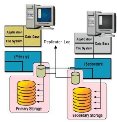
Understanding replication in the VVR environment
This section describes the VVR replication process and explains the VVR setup at the primary and secondary host.
Figure 1-2 VVR replication process
VVR at the primary
VVR is configured such that the volumes to be replicated for a specific application are placed in an RVG. Writes to the data volumes are persistently queued in the Replicator Log Volume. VVR uses the Replicator Log volume to track all the writes in the order in which they were received and VVR transmits the writes to the secondary using the Replication Link (RLINK). You can choose to use either the UDP protocol or TCP protocol for network communication between the primary and secondary.
The Replicator Log volume is a SFW volume configured as part of an RVG. On the primary, each write to an RVG generates two writes; first to the Replicator Log volume and then to the data volume. Only the write to the Replicator Log volume affects the application. The write to the data volume is written in the background and does not affect application performance.
If the primary crashes at any point before the write to the data volume is completed, data is fully recoverable from the Replicator Log volume. This is very similar to a database writing to a redo log and later writing to the data files. VVR supports several methods to initialize the application data between the primary location and the remote location which are as follows:
■ Automatic synchronization using DCM
■ Checkpoints that can be used with block level backups
■ Disk group split and join operation, which can be used to move the disks physically to the secondary site
VVR at the secondary
VVR sends data to the secondary RVG as a message, based on the application write size. Each write (update) is divided into one or multiple packets based on the predefined packet size specified for a secondary. These packets are later assembled at the secondary. When the secondary receives the message, the secondary immediately sends an initial acknowledgement of receipt. This is known as the network acknowledgement.
The network acknowledgement allows the primary to immediately continue processing, as required. The data is not yet written to disk on the secondary RVG, but it is still safe because it is stored in the primary Replicator Log volume. After the secondary writes to the local disk, it sends the second
acknowledgement, the data acknowledgement. When the primary receives the data acknowledgement this write is discarded from the Replicator Log volume. The reason for the two-phase acknowledgement is performance. In synchronous mode, the primary waits for the network acknowledgement from the secondary before it completes the write for the application. If VVR were to wait for the write to complete on the primary and the secondary, it would increase latency considerably. By using the two-phase acknowledgment, VVR maintains application performance. Because data is persistently queued in the primary Replicator Log volume, safety of the data for the secondary is maintained. At the secondary host, VVR holds the packets until all the previous packets have been received. It then writes to the disks in the correct sequence to maintain consistency at the secondary. Holding the packets in memory enables VVR to reassemble out-of-order network traffic before writing, and discover and handle missing packets. To maintain consistency at the secondary RVG, VVR never writes an I/O out of order with the primary RVG. Incoming data from the primary RVG is serialized and checksummed to support accurate replay to the secondary volumes.
The secondary Replicator Log volume is only used in very specific conditions which are as follows:
■ During recovery, after a primary or secondary crash ■ To store state of actual underlying volume plexes ■ During IBC messaging to a secondary
How replication happens in the VVR environment
The replication process allows data to be replicated across the room or across the world automatically. In general, replication can be used for disaster recovery, providing high availability for the application and data, and load balancing. VVR is a replication service that provides disaster recovery facility. When replicating, VVR sends updates from the primary host on which the application is running, to the remote host that is the secondary. VVR
Replication is a unidirectional process, whereby the updates on the primary host are sent to the secondary host. A VVR setup can have one or more secondary hosts.
Warning: You must ensure that no file systems are mounted on the secondary when replication is active as this could result in data loss.
If the data at the primary gets destroyed, one of secondary hosts can be made the primary to make the data write-accessible. You can then restart the applications on that secondary.
See “Using VVR as a disaster recovery tool” on page 39 for details.
Modes of replication
The Veritas Volume Replicator replicates data in three modes. They are as follows:
■ Synchronous ■ Asynchronous ■ Synchronous override
Each of the modes follows a different method to replicate the data, and behaves differently under different network conditions. You can choose the mode of replication depending on your specific requirements.
The choice of modes of replication is also determined by the following: ■ Available bandwidth
■ Network round-trip time ■ Number of participating hosts ■ Amount of data to be replicated ■ Geographical distance
Irrespective of the mode that you choose for replication, VVR maintains complete data integrity. You must, however, ensure that average bandwidth of your network must be adequate for the update rate of the application.
Synchronous mode of replication
The synchronous mode of replication ensures that an update has been acknowledged by the secondary host, before completing the update at the primary. In the case of a problem such as a network failure, it ensures that the update fails at the primary itself.
The synchronous mode of replication is most effective in the following: ■ Application environments that have lower update rates but require all the
hosts to always reflect the same data
■ Applications where lag in updates between the primary and secondary host is not acceptable
Advantage of synchronous mode of replication
In the event of a disaster at the primary host, data can be recovered from the surviving secondary host without any loss, because the primary and the secondary host contain the same data.
Disadvantages of synchronous mode of replication
The response time experienced by the writing application is affected because the application has to wait for an acknowledgment from the secondary before it can complete an update.
The following suggestions help to work around the disadvantages to some extent:
■ Add network bandwidth to reduce the degradation in update response time experienced by the application.
■ Reduce the network round-trip time between each primary and secondary pair by using faster network technologies.
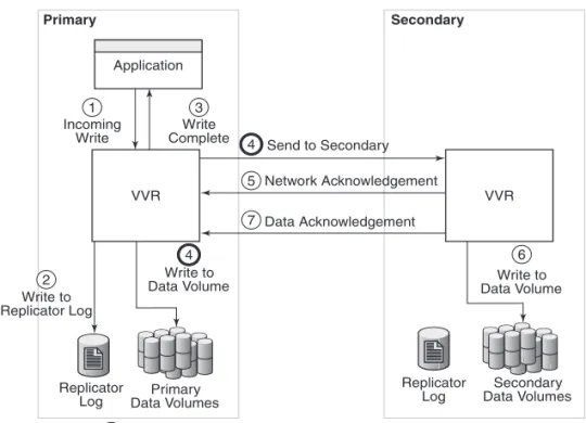
Understanding data flow in VVR synchronous mode
This section explains how VVR processes an incoming write when replicating in synchronous mode.
Figure 1-3 VVR processing incoming writes in a synchronous mode.
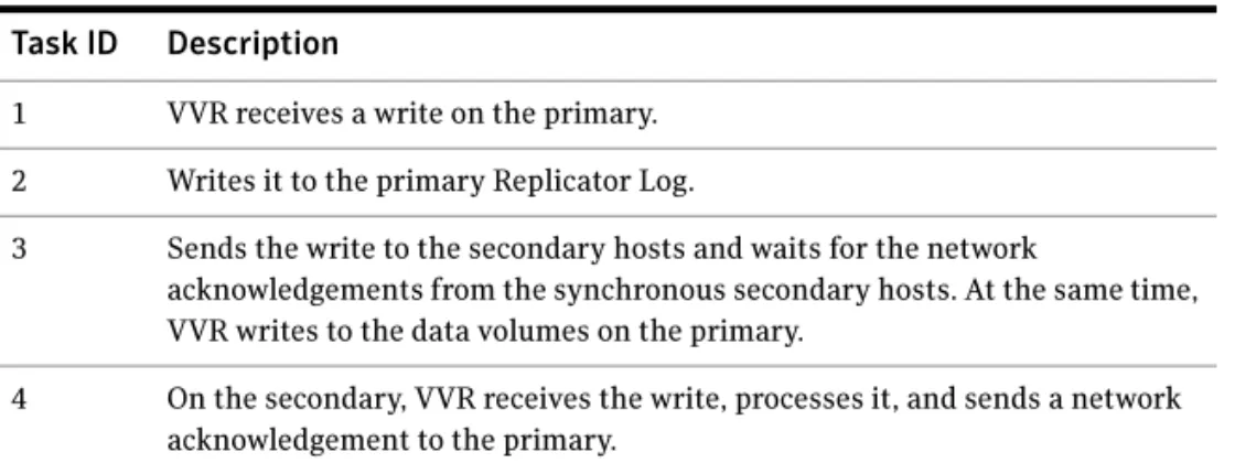
In synchronous mode of replication, VVR processes an incoming write as follows:
Table 1-1 Task ID and related description of replication in synchronous mode. Task ID Description
1 VVR receives a write on the primary. 2 Writes it to the primary Replicator Log.
3 Sends the write to the secondary hosts and waits for the network
acknowledgements from the synchronous secondary hosts. At the same time, VVR writes to the data volumes on the primary.
4 On the secondary, VVR receives the write, processes it, and sends a network acknowledgement to the primary.
VVR Primary Secondary VVR Secondary Data Volumes Primary Data Volumes Replicator Log Replicator Log Application
Indicates operation being performed simultaneously. 5 1 Incoming Write 2 Write to Replicator Log 3 Write to Data Volume 5 Write Complete Write to Data Volume Send to Secondary 3 Network Acknowledgement 4 Data Acknowledgement 6 5 5
When an RDS containing multiple secondary RVGs is replicating in synchronous mode, the application latency is determined by the slowest synchronous secondary. Overall performance in synchronous mode is determined by the time to write to the Replicator Log Volume, plus the round-trip time required to send data to the secondary RVG and receive the acknowledgement.
5 Sends writes to the data volumes on the secondary; when the primary receives a network acknowledgement from all the secondary hosts, VVR acknowledges to the application that the write is complete.
The secondary RVG sends the network acknowledgement as soon as the write is received. This eliminates the time required to write to the secondary data volumes from the application latency. On the primary, VVR does not wait for data to be written to the secondary data volumes. This improves application performance. However, VVR tracks all such acknowledged writes that have not been written to the data volumes. VVR can replay these tracked writes if the secondary crashes before writing to the data volumes on the secondary or if the primary crashes before it receives the data acknowledgement.
6 When the write is written to the data volumes on the secondary, VVR on the secondary sends a data acknowledgement to the primary.
Asynchronous mode of replication
In the asynchronous mode of replication, the application updates are
immediately reflected at the primary, but are sent to the secondary later. The updates are stored in the Replicator Log until they are sent to the secondary. If the writing application experiences a temporary increase in update rate, this delay may increase.
If a disaster strikes during a period of peak update activity, it is possible that the most recent updates at the primary host are not reflected in the data at the secondary host. This is because of the lag between the primary and secondary data states, which is called latency. To prevent this, you can configure the latency such that in the event of a disaster the data lag will be within acceptable limits. Asynchronous replication ensures that the lag never exceeds this configured maximum.
Advantages of Asynchronous mode of replication
This section explains certain advantages of replicating in the Asynchronous mode.
Some advantages of the asynchronous mode of replication are as follows: ■ The writing application does not suffer from the response time degradation,
as there is no network round-trip overhead for each update.
■ The rate at which the Replicator Log is being drained depends on the maximum available bandwidth or the maximum specified bandwidth. During periods when the update rate is less than the available network bandwidth, the Replicator Log drains faster than it grows. This allows the secondary data state to catch up with that on the primary.
■ Assures that all completed updates to the primary volumes are made on the secondary data volumes, even though it may be with some delay. This is true even in case of failures in communication or system crashes on any of the participating hosts.
■ Asynchronous replication can easily handle the temporary network or the secondary host failure because of its ability to queue updates persistently, and hold them at the primary for later transmission.
Disadvantages of Asynchronous mode of replication
This section explains disadvantages of asynchronous mode of replication. Some disadvantages of the asynchronous mode of replication are as follows: ■ The improvement in response time is at the cost of the data at the secondary■ The volumes at a secondary host may not have the latest updates when the primary role is taken over by a secondary.
Understanding data flow in VVR asynchronous
mode
This section explains how VVR processes an incoming write when replicating in asynchronous mode.
Figure 1-4 VVR processing writes in the asynchronous mode
In asynchronous mode of replication, VVR processes an incoming write as follows:
Table 1-2 Task ID and related description for replication in the asynchronous mode
Task ID Description
1 VVR receives a write on the primary. 2 Writes it to the primary Replicator Log.
3 On the primary, acknowledges to the application that the write is complete.
Replicator Log Replicator Log Primary Secondary VVR VVR Application Secondary Data Volumes Primary Data Volumes
Indicates operation being performed simultaneously. Send to Secondary 4 Network Acknowledgement 5 Data Acknowledgement 7 1 Incoming Write 2 Write to Replicator Log 4 Write to Data Volume 3 Write Complete 6 Write to Data Volume 4
Synchronous override mode
The synchronous override mode of replication is a mode where replication is synchronous, as long as the network is available. If the network becomes unavailable, then replication is continued in the asynchronous mode. The pending updates are sent to the secondary when the network becomes available. When the data becomes completely synchronized then the replication mode reverts back to being synchronous. Depending on specific needs where you would like to have synchronous replication, you can use the synchronous override mode of replication for maximum continuity.
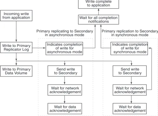
Understanding data flow in an
RDS that contains multiple secondary hosts
An RDS can have multiple secondary hosts. This section explains how VVR processes an incoming write for a Replicated Data Set containing multiple secondary hosts, some replicating in asynchronous mode and some in synchronous mode.
4 Sends the writes to the asynchronous secondary hosts, in the order in which they were received on the primary, and at the same time, writes to the primary data volumes.
5 When the primary receives the network acknowledgement, it knows that the write has been received in the secondary VVR memory buffer.
6 VVR sends the writes to the data volumes on the secondary and then sends a data acknowledgement to the primary.
7 When the primary receives the data acknowledgement, VVR marks the write as complete in the Replicator Log.
Table 1-2 Task ID and related description for replication in the asynchronous mode
Figure 1-5 VVR processing writes for multiple secondary hosts in an RDS.
In asynchronous and synchronous mode of replication, VVR processes an incoming write as follows, in the presented order:
■ Receives a write from the application. ■ Writes it to the Replicator Log.
■ VVR first sends the update to all the secondary hosts replicating in synchronous mode. It then writes to the data volumes under the primary RVG, and then sends it to the secondary hosts replicating in asynchronous mode.
■ On the secondary, VVR receives the write, processes it, and sends a network acknowledgement to the primary.
■ When the primary receives a network acknowledgement from the secondary hosts replicating in synchronous mode, VVR acknowledges to the
application that the write is complete. The secondary RVG sends the network acknowledgement as soon as the write is received. This eliminates the time required to write to the secondary data volumes from the
application latency. On the primary, VVR waits only for the network acknowledgement from all the synchronous secondary hosts and not for the data to be written to the secondary data volumes. This improves application performance. However, VVR tracks all such acknowledged writes that have
Send write to Secondary Indicates completion of write for synchronous mode Indicates completion of write for asynchronous mode Write complete to application
Wait for all completion notifications Incoming write from application Write to Primary Replicator Log Write to Primary Data Volume
Primary replication to Secondary in synchronous mode Primary replicating to Secondary
in asynchronous mode
Wait for network acknowledgement
Wait for data acknowledgement Send write
to Secondary
Wait for network acknowledgement
Wait for data acknowledgement
not been written to the data volumes. VVR can replay these tracked writes if the secondary crashes before writing to the data volumes on the secondary or if the primary crashes before receiving the data acknowledgement. ■ When the write is written to the data volumes on the secondary, VVR sends
a data acknowledgement from the secondary to the primary in both synchronous and asynchronous mode.
■ When the primary receives the data acknowledgement from all the secondary hosts, VVR marks the write as complete in the Replicator Log.
Managing data during failure and recovery
This section gives an overview of the methods of preventing data loss and maintaining data consistency even during a failure and subsequent recovery process.
Some concerns that need to be considered during a failure and the subsequent recovery are as follows:
■ Preventing data loss
■ Maintaining data consistency
■ Detecting host and connection failures ■ Securing VVR
Preventing data loss
This section describes the techniques that VVR uses to prevent data loss.
Preventing data loss during normal operations
During normal operation, VVR prevents data loss by logging all the updates to the primary Replicator Log volume and ensuring that this operation is completed before writing to the primary and secondary data volumes. The primary Replicator Log volume can be used to obtain the correct contents of all the data volumes, except in the case of failure of the primary Replicator Log volume or the data volume itself.
Preventing data loss during a primary host failure
In the case of a primary host failure, the primary data volumes may slightly lag behind the primary Replicator Log volume. During recovery, the first primary Replicator Log volume entry that has not yet been written to the data volumes is identified, and the primary Replicator Log volume is replayed from that point. During the recovery period, the RVG is not available for Input/Output
operations. The recovery time is short because there are only a few blocks that have not been written to the data volumes.
VVR also supports fast-failback to the original primary, once the original primary becomes available. This is achieved by using the DCM logs. See “Performing takeover with fast-failback” on page 40.
Maintaining data consistency
Data consistency is maintained by co-ordinating operations in such a way that they maintain the write-order on each secondary as on the primary. The primary Replicator Log volume is time-ordered and contains the data for each individual write. The disk modifications also occur in the same order on the secondary as on the primary.
If the primary recovers after a crash, VVR locates the last entry in the primary Replicator Log volume that had not been acknowledged by the secondary as successful, before the crash. Updates to this secondary will continue from that point onwards.
When the primary or secondary crashes, the VVR recovery process ensures that all the pending updates on the primary are sent to the secondary in such a way that there is no data loss, and the data is consistent at the end of the recovery. secondary Replicator Log is used for this purpose.
VVR is designed to maintain consistency between the primary RVG and the secondary RVG even in the event of network failures and the temporary loss of the primary or secondary host, or both. When the problem is corrected, and the primary and secondary are again both active and able to communicate, the primary and secondary automatically resynchronize themselves and continue replication. A secondary may become temporarily inconsistent during this resynchronization phase. However, because synchronization is achieved in a protected manner, a subsequent network or host failure during this phase cannot cause inconsistency on the secondary, even if the primary host is permanently lost.
Detecting host and connection failures
The primary and secondary hosts exchange messages periodically even when there is no replication activity using the Heartbeat protocol. This helps to detect host or connection failure between the primary and secondary.
Securing VVR
Veritas Volume Replicator is capable of replicating over a firewall and also supports Network Address Translation (NAT).
VVR operations can be performed directly from the VEA or using the CLI. You can perform the operations on the various VVR objects which include RVG, RDS, replicated volumes and the RLINKs (secondaries). Some VVR operations involve more than one host as a part of their operations. Before executing such an operation, VVR first validates whether the originator host is allowed to execute the specified operation on the target hosts. If not, the specified operation fails. This validation process is referred to as the security check and is managed by the Veritas Volume Replicator Security Service (VxSAS) wizard.
These measures provide a higher level of security to your application and data. See “Security considerations for VVR” on page 78.
Chapter
2
Replication concepts
This chapter explains the important concepts of VVR, the most important one, its ability to transfer the primary role, and fail back. Symantec recommends that you read this chapter before setting up replication.
For information on RLINKs, see “Replication Link—RLINK” on page 23.
Using VVR as a disaster recovery tool
One of the key advantages of VVR is its capability to provide a disaster recovery solution. In the case of a primary host failure or a disaster at the primary site, it may become necessary to transfer the role of the primary to the secondary. At times, it may be necessary to bring down the primary host for maintenance purposes. This can be achieved by transferring the primary role to any secondary having up-to-date data.
For detailed information about configuring DR solutions, see the following documents:
■ Veritas Storage Foundation™ and High Availability Solutions, Solutions Guide
■ Veritas Storage Foundation™ and High Availability Solutions HA and Disaster Recovery Solutions Guide for Microsoft Exchange 2003 ■ Veritas Storage Foundation™ and High Availability Solutions HA and
Disaster Recovery Solutions Guide for Microsoft Exchange 2007 ■ Veritas Storage Foundation™ and High Availability Solutions HA and
Disaster Recovery Solutions Guide for Microsoft SQL 2000 and 2005 ■ Veritas Storage Foundation™ and High Availability Solutions HA and
Disaster Recovery Solutions Guide for Microsoft SQL 2008
VVR enables you to transfer the primary role from a healthy or failed primary using the Graphical User Interface (GUI) or the command line options. It also enables you to fail back to the original primary using a simple set of operations.
VVR offers the following methods to transfer the primary role: ■ Migrating the primary role
■ Taking over the primary role
■ Performing takeover with fast-failback
Migrating the primary role
Migrating the primary role involves interchanging the role of a healthy primary with that of a secondary, when the application involved in replication is inactive. You can also plan to change the role of the primary if you need to perform some maintenance activities or some other configuration changes to the primary. To migrate successfully, the data between the primary and the secondary must be up-to-date.
VVR provides options from the GUI as well as the command line to migrate a healthy primary. The migrate operation involves migrating the primary role of an RVG to a secondary, thus converting the secondary RVG to a primary RVG.
Taking over the primary role
When the original primary fails or is destroyed because of a disaster, the takeover procedure enables you to convert a consistent secondary to a primary. To determine whether takeover of the primary by a secondary will be successful, you must first consider whether the data is consistent and how up-to-date it is. VVR provides the takeover operation to transfer the primary role both from the graphical user interface as well as the command line.
Note: The takeover operation can be performed only on the secondary host, when the primary becomes unavailable, or the secondary cannot communicate with the primary.
Upon successful completion of the takeover, the secondary becomes the primary.
Performing takeover with fast-failback
In the case of a primary failure or if the primary needs to be brought down for some maintenance tasks, the role of the primary needs to be taken over by the Secondary. When the old (original) primary comes up you can failback from the new primary to the original primary. The fast-failback feature enables you to do this quickly and efficiently as it performs incremental synchronization, for only the changed data. This feature uses the DCMs of the data volumes of the new
primary, to keep track of the changed content and the new content. This process of logging on the DCM is called failback logging.
You can perform the takeover operation with fast-failback by selecting the failback logging option on one of the secondaries. After the takeover operation is complete the applications are started on the new primary. All the subsequent writes from the applications running on the new primary are then tracked on the DCM of the new primary. When the original primary recovers, it discovers that one of its scondaries has taken over as the new primary and it starts acting as a secondary. The synchronization to the original primary can be started manually or automatically depending on the options specified during takeover. The RVG volumes on the original primary will now disallow access permissions to the applications and need to be synchronized with the new primary by playing back the DCM. You will need to perform the resynchronization operation to start the DCM replay. At the start of the DCM replay, the original primary becomes a secondary and starts receiving the missing updates. You can then continue to use the current setup after takeover, as is, or, you can complete the failback process by using the migrate operation to change the primary role back to the original primary. If you want to migrate the role of primary back to the original primary then you will not need to perform the operation to add the other secondaries back to the original primary. The RLINKs from the other secondaries to the original primary are still retained, and once the primary role is migrated back to the original primary (current secondary), these secondaries will automatically become secondary hosts to the original primary.
Understanding how VVR logs writes to the
Replicator Log
VVR receives writes from the application and queues them in the primary Replicator Log for transmission to the secondary hosts. If a primary RVG is connected to multiple secondary RVGs, the Replicator Log on the primary is used to manage the writes for these secondary hosts. The Replicator Log header contains a specific set of pointers for each secondary which indicates the writes that have not been sent to the corresponding secondary.
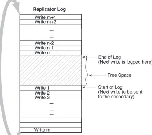
Figure 2-6 Illustrates the working of the Replicator Log as a circular buffer
The Figure 2-6 shows how writes are logged in the Replicator Log. The first write that comes in is Write 1, which also represents the Start of Log for the
Secondary. VVR logs Write 2, Write 3, Write m one after the other until it reaches the end of the Replicator Log. Because the Replicator Log is a circular log the next write, Write m+1 wraps around and logging continues. When the primary receives the data acknowledgement from this secondary host for Write 1, VVR marks the Write 1 as complete in the Replicator Log. VVR then processes Write 2, Write 3, and so on.
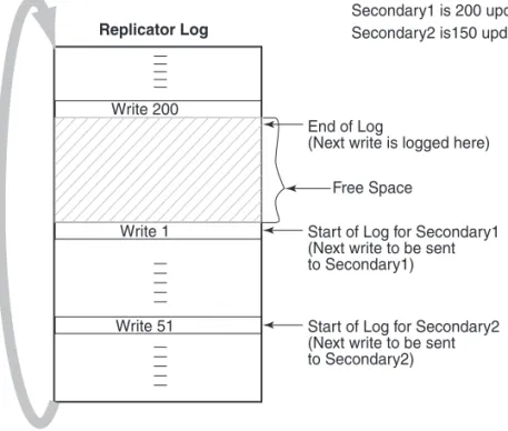
In Figure 2-7 on page 43, secondary1 is 200 writes or updates behind, whereas secondary2 is 150 writes behind. If the End of Log pointer reaches the Start of Log pointer of the secondary, the Replicator Log overflows for this secondary.
Replicator Log Write m+1 Write m+2 Write n-1 Write n Write 1 Write m Write 2 Write 3 Write n-2 Start of Log
(Next write to be sent to the secondary) End of Log
(Next write is logged here) Free Space
Figure 2-7 The working of the Replicator Log when the secondary is behind
The secondary hosts for which the replication is configured in synchronous mode are usually up-to-date. Typically, the Start of Log and End of Log pointers of synchronous RLINKs (secondaries) are separated by the number of
simultaneous I/O operations the application performs. For asynchronous RLINKs, the difference between the Start of Log pointer and End of Log pointers reflect how many outstanding writes have yet to be processed, that is, how behind is the RLINK. Different RLINKs usually have Start of Log pointers indicating different places in the Replicator Log; this reflects the difference in the rate at which data is sent to the secondary. After the primary receives the data acknowledgement from all the secondary hosts, VVR marks the write as complete in the Replicator Log volume.
Sizing the Replicator Log
The size of the Replicator Log is critical to the performance of replication. In the asynchronous mode of replication, due to network latency, the writes may be pending on the primary Replicator Log. In this, case the primary Replicator Log may overflow if the number of pending writes exceed the number of updates it can store.
Replicator Log
Write 200
Write 1 Start of Log for Secondary1
(Next write to be sent to Secondary1)
Write 51 Start of Log for Secondary2 (Next write to be sent to Secondary2)
Secondary1 is 200 updates behind Secondary2 is150 updates behind
End of Log
(Next write is logged here) Free Space
When the Replicator Log overflows for a particular secondary, the RLINK corresponding to that secondary is marked STALE and becomes out of date until a complete resynchronization with the primary is performed. Because
resynchronization is a time-consuming process and during this time the data on the secondary cannot be used, it is important to avoid Replicator Log overflows. Thus, the Replicator Log size needs to be large enough to satisfy the following constraints:
■ It must not overflow for asynchronous RLINKs during periods of peak usage when replication over the RLINK may fall far behind the application. ■ It must not overflow while a secondary RVG is being synchronized. ■ It must not overflow while a secondary RVG is being restored.
■ It must not overflow during extended outages (network or secondary node).
Determining the size of the Replicator Log
To determine the size of the Replicator Log, you must evaluate each of the following constraints individually. Then, choose a value at least equal to the maximum so that all constraints are satisfied.
The following information is needed to perform the analysis to determine the size of the Replicator Log:
■ The maximum expected downtime for secondary nodes. ■ The maximum expected downtime for the network connection. ■ The method for synchronizing secondary data volumes with data from
primary data volumes.
If the application is shut down to perform the synchronization, the Replicator Log is not used and the method is not important. Otherwise, this information could include, the time required to copy the data over a network, or the time required to copy it to a tape or disk, to send the copy to the secondary site, and to load the data onto the secondary data volumes. Note: If you are using the Synchronize Automatically option from VEA, to synchronize the secondary, the previous paragraph is not a concern. In the case of secondary data volume failure if you are going to perform Secondary backup to avoid complete synchronization, the information needed includes:
■ The frequency of secondary backups.
■ The maximum expected delay to detect and repair a failed secondary data volume.