I
NTELLIGENT TUTOR TO LEARN
THE EVALUATION OF MICROCONTROLLER
I
/
O PROGRAMMING EXPRESSIONS
MASTER THESIS IN SOFTWARE ENGINEERING
STUDENT HUGO ARENDS
STUDENT NUMBER 851695207
I
NTELLIGENT TUTOR TO LEARN
THE EVALUATION OF MICROCONTROLLER
I
/
O PROGRAMMING EXPRESSIONS
MASTER THESIS IN SOFTWARE ENGINEERING
OPEN UNIVERSITY OF THE NETHERLANDS,
FACULTY OF MANAGEMENT,SCIENCE &TECHNOLOGY
MASTER SOFTWARE ENGINEERING
STUDENT ING.HUGO ARENDS
STUDENT NUMBER 851695207 PRESENTATION 02/03/2017
CHAIRMAN PROF. DR.JOHAN JEURING
SUPERVISOR DR.BASTIAAN HEEREN
2ND SUPERVISOR IR.HIEKE KEUNING
V
SUMMARY
Learning how microcontroller I/O programming expressions evaluate to a normal form is a vital task for students learning how to create embedded systems. Bitwise and logic operators for manipulating variables are a key factor for this domain. Typical expressions for this domain involve looping until a bit is set and updating specific bits in an hardware register. Each expression can have numerous evaluations, and all evaluations lead to the same normal form.
The intelligent tutoring system (ITS) prototype for learning the evaluation of microcontroller I/O programming expressions that was designed, implemented, and tested for this research project, solves the problem that, although no human tutor is available, students are guided step-by-step towards a solution. Such an ITS consists of two major building blocks: a front-end and a back-end. The front-end is realized as a web application. The main part of the back-end is the domain reasoner, which is realized using the IDEAS framework. A domain reasoner is a software program that helps students solve interactive exercises for a specific problem domain.
The domain of microcontroller I/O programming expressions is characterized by a diversity of microcontrollers and programming languages. The main contribution of this research project is the answer to the question how an ITS for this domain is capable of handling this diversity. The answer is a domain reasoner that is configurable by dynamically creating exercises from configuration files. Multiple microcontrollers are supported by parsing definitions from files as keyword and value pairs into a lookup environment. This environment is used whenever a definition or variable must be substituted. Multiple imperative programming languages are supported by allowing tokens from the grammar to be specified in a language definition file. This definition is also parsed into a lookup environment that is used during parsing and pretty printing.
The diagnose service is used to analyse a student’s step and calculate a feedback message. It was unexpected that the default diagnose service of the IDEAS framework is not suitable for this domain. The problem is that the IDEAS framework assumes that if two expressions are semantically equivalent, the student always takes a correct evaluation step. This is not necessarily true. The problem is solved by creating a custom diagnose service, which introduces a new equivalence relation that determines the semantic equivalence of all delta pairs. A delta pair is the maximum subexpression that is different when two expressions are compared.
It helps students to understand the evaluation of microcontroller I/O programming expressions, when the nature of feedback messages is related to explanations on subject matter, solution errors, and task-processing steps. These types of messages guide students step-by-step towards a solution.
The research project is validated by questionnaires filled in by students and lecturers. Quantitative results show that the prototype behaves as expected from a student’s point of view and that the new diagnoses are relevant for this domain. Qualitative results show that the feedback and hint messages help students towards a solution and contributes in understanding how microcontroller I/O programming expressions evaluate.
VII
ACKNOWLEDGEMENTS
Today, an exciting period comes to an end: the finishing touch on this thesis. A lot of people were helpful to me during this period and I would like to take the opportunity to thank them here.
First of all I would like to thank the first year HAN Electrical and Electronic Engineering bachelor students, main phase students from the HAN minor Embedded Vision Design, and colleagues from HAN University of Applied Sciences who participated in the surveys.
My family and friends were always very understanding when I spent time on the research project. Many thanks to all of you for being who you are!
I would also like to thank my employer HAN University of Applied Sciences for giving me the opportunity to follow this education.
Last, but not least, I would like to thank my research committee for their support and guidance during the research project. I would particularly like to single out my supervisor Bastiaan Heeren. Bastiaan, I am grateful for your feedback and hints and I enjoyed our skype meetings that always guided me in the right direction. You encouraged me to get to the bottom of things, which helped me in making this research project and thesis as they are today.
Thank you very much, everyone! Hugo Arends
IX
CONTENTS
Introduction ... 1 Microcontroller teaching ... 3 2.1 Software development ... 3 2.2 Teaching methods ... 8 2.3 Expression evaluation ... 9 Research assignment ... 13 3.1 Research questions ... 13 3.2 Research method ... 14 3.3 Research scope ... 15 Example session ... 17 4.1 Student interaction ... 17 4.2 Instructor interaction ... 21An ITS for microcontroller I/O programming ... 23
5.1 Web application ... 23 5.2 Domain reasoner... 24 5.3 Diagnosis ... 39 Validation ... 49 6.1 Survey setup ... 49 6.2 Quantitative results ... 50 6.3 Qualitative results ... 54 Related work ... 59
7.1 Intelligent tutoring systems ... 59
7.2 Evaluation of programming expressions ... 60
7.3 Comparison to other programming tutors ... 63
Discussion ... 67
Conclusion ... 71
Bibliography ... 73
A Exercise configuration file ... 77
B Language definition files ... 79
C Script file ... 81
D Diagnosis with a binary decision tree ... 83
E Expressions evaluated in surveys... 85
XI
LIST OF FIGURES
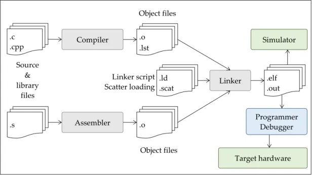
Figure 1. Typical steps from source and library files to executing on target hardware or simulator in an
SDE for microcontroller software. ... 3
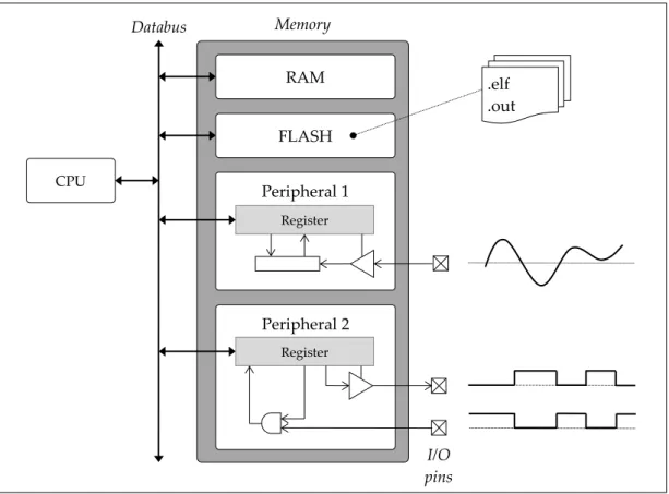
Figure 2. Simplified microcontroller block diagram showing how RAM, machine instructions and peripherals all are parts within the memory map. ... 4
Figure 3. Visualisation technique used by Dolman to explain the evaluation of a composite expression (Dolman, 2010). ... 8
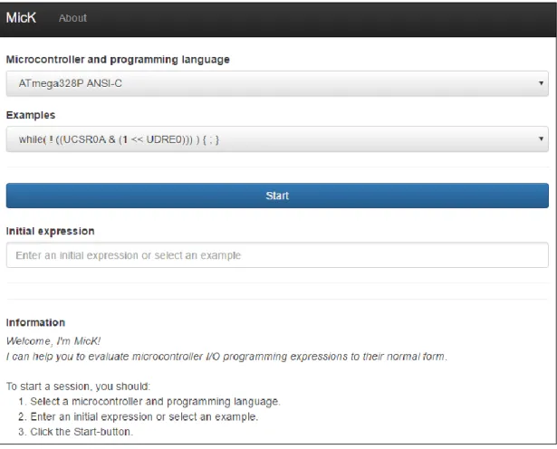
Figure 4. Initial screen of the web-based front-end of MicK. ... 17
Figure 5. After pressing the Start button, the student is asked to enter the next evaluation step. ... 18
Figure 6. The student has finished a task successfully. ... 20
Figure 7. The building blocks of the ITS prototype. ... 23
Figure 8. Several components of an exercise and their dependencies. ... 25
Figure 9. Parse tree for the expression while(!(UCSR0A & (1<<UDRE0))){;}. ... 26
Figure 10. Simplified AST for the expression while(!(UCSR0A & (1<<UDRE0))){;}. ... 27
Figure 11. Configuration files from the Exercises folder are parsed and exercises are dynamically generated. ... 29
Figure 12. Parsers for the definition files and the internal representation for each exercise. ... 30
Figure 13. The two simplified ASTs for 𝑥, 𝑦 = 𝑤ℎ𝑖𝑙𝑒1 & 2 𝑎 = 3 + 4; , 𝑤ℎ𝑖𝑙𝑒0 𝑎 = 7; and visualizing the two delta pairs with corresponding colours. ... 40
Figure 14. Algorithm for simultaneously traversing two ASTs and checking if nodes are identical or semantically equivalent. ... 41
Figure 15. Venn diagram for visualizing the characteristics of the subsets. ... 42
Figure 16. A debugging session in Atmel Studio to visualize the data from the ATmega328P on-chip debugger. ... 61
Figure 17. Practicing with bitwise operators in Kumar's online tutor on expression evaluation. ... 62
Figure 18. The practice part of Olmer's tutor for practicing with the evaluation of Haskell expressions. ... 63
XII
LIST OF TABLES
Table 1. Example elements 𝑥, 𝑦 ∈ 𝐸2 and if the element is an element of each of the six subsets. ... 42 Table 2. Truth table for diagnosing an element 𝑥, 𝑦 ∈ 𝐸2 in the prototype. The highlighted diagnosis is
new with respect to the IDEAS framework (v1.5). ... 46 Table 3. Results from quantitative analysis of the surveys with students and instructors. ... 50 Table 4. Results from quantitative analysis of the log database. ... 51 Table 5. Log entries that pointed out a bug in the pretty printer (session id 3472d6142c5f19e0c57a). ... 52 Table 6. Log entries showing how a student creates a worked-out example (session id
a09e2dbe5df4154a2385). ... 52 Table 7. Log entries showing how a student only validates expressions in their normal form (session id
9a8a1f16ce1be6e80e30). ... 53 Table 8. First entries from a logging session, showing how a student submits a semantic equivalent
expression, but takes a wrong step (session id 3c57c1c6c3205ca43a35). ... 54 Table 9. Features in example-based environents (Gómez-Albarrán, 2005) and their implementation in
1 INTRODUCTION 1
I
NTRODUCTION
The internet of things, robotics, virtual home assistants, smart systems, and many more are vital systems within today’s connected society. What these systems all have in common is that they use one or more microcontroller to get information from sensors, to manipulate this information, and to control actuators based on this information. To build these microcontroller-based systems, students need to learn both hardware and software skills. These skills are taught in embedded systems education both at the bachelor and master level, but there are also many communities where one can learn how to build systems with microcontrollers. The most effective way to learn in general, also for developing microcontroller systems, is the availability of an expert human teacher for one-to-one instruction (Bloom, 1984). With an increasing popularity of embedded systems education, distance education, and online learning, the constant availability of experts is nowhere near this ideal situation.
This is where intelligent tutoring systems (ITS) offer a solution. An ITS is a software application designed to simulate a human tutor’s behaviour and it can play many different roles in the student’s learning process (VanLehn, 2006). The development of this technology started in the late 1960s and although significant progress has been made, the developmental complexity requires a considerable amount of manual effort. For this reason, ITSs have not been widely available. Over the past decade there has been a modest revival (Keuning, 2014) with a growing number of web-based tutors, which probably is related to the increasing popularity of online learning.
The main purpose of the research described in this thesis is to investigate how an ITS is useful within the microcontroller teaching domain. Although it would be interesting to also investigate this for hardware development, the scope of this research project is microcontroller software development. This is introduced in Section 2 by discussing how software is developed for microcontrollers and teaching methods for microcontroller programming. Section 3 discusses the research assignment by presenting the research questions, the research method, and the research scope. An example session from a student’s and an instructor’s point of view is shown in Section 4. Section 5 discusses the realization of an ITS for microcontroller I/O programming, which is validated in Section 6 by analysing the answers from surveys and log entries. Related work is discussed in Section 7. Section 8 reflects on the research project and discusses future work. Finally, the research project is concluded by providing an answer to the research questions in Section 9.
2 MICROCONTROLLER TEACHING 3
M
ICROCONTROLLER TEACHING
This section provides an overview of subjects that are related to teaching microcontroller programming. Section 2.1 describes the typical steps for developing software for microcontrollers. Teaching methods for microcontroller programming are described in Section 2.2. Finally, Section 2.3 presents a detailed description of the evaluation of microcontroller I/O programming expressions.
2.1
Software development
A microcontroller is the combination of a microprocessor core, memory and programmable I/O peripherals, all in a single integrated circuit (IC). Microcontrollers are used in embedded systems. They are preferred in applications where physical dimension, high performance and long battery life are important design decisions. There is no microcontroller specific programming language. Software can be written in many different low-level and high-level programming languages as long as there is a compiler, interpreter, assembler, linker or other translation tool available that is capable of creating microcontroller-specific machine instructions. Nowadays, the majority of microcontrollers is programmed in C or C++. This is due to the nature of these languages, because they provide constructs that efficiently map to machine instructions and I/O operations.
Figure 1. Typical steps from source and library files to executing on target hardware or simulator in an SDE for microcontroller software. .o .lst .c .cpp Object files .ld .scat Linker script Scatter loading .o .s Assembler Object files Compiler Linker .elf .out Simulator Target hardware Source & library files Programmer Debugger
4 2 MICROCONTROLLER TEACHING
The typical steps taken within a microcontroller software development environment (SDE) are depicted in Figure 1. Source files are created by developers, or are provided as a library, for instance by microcontroller vendors or communities. Translation software, such as compilers and assemblers, turn source files into object files. Although these files already contain machine code, a linker is used to combine and map several object files to the microcontroller specific memory layout, which is prescribed in a scatter loading file. Within an SDE, compiling and linking is often merged into one step with the use of makefiles. The resulting executable file is ready for use in a simulator or is programmed in a target microcontroller with a programmer or debugger.
Figure 2. Simplified microcontroller block diagram showing how RAM, machine instructions and peripherals all are parts within the memory map.
For embedded systems engineers, software development for microcontrollers starts with the creation of source files, just as in application development for personal computers. The software design for microcontroller applications, however, is generally speaking less comprehensive, because software is created for a very specific purpose. Another difference is caused by what is called I/O programming as depicted in Figure 2. The central processing unit (CPU) executes machine instructions, stored in flash memory, to directly control hardware that is connected to the I/O pins of the microcontroller on a printed circuit board (PCB). The hardware inside the microcontroller that is controlled by software is called a peripheral. Peripherals are
Peripheral 1 .elf .out RAM FLASH Register Peripheral 2 Databus CPU I/O pins Memory
Register
2 MICROCONTROLLER TEACHING 5
controlled by software by means of registers. These registers are mapped to memory addresses and by addressing a specific memory location a register is read and written. This is called memory mapped I/O and is depicted in Figure 2. Another way of performing I/O operations is called port mapped I/O where only a dedicated set of CPU instructions perform input and output operations. When programming in a high-level programming language the compiler takes care of selecting the appropriate machine instructions.
All microcontroller software applications utilize the same basic high level design. After initialization of peripherals and variables, an endless loop reads sensors, processes data and controls actuators. To initialize and use a peripheral, bits in the registers must be set to specific logic values. The meaning and usage of the registers and bits is described by the microcontroller vendor in a document called the datasheet.
An example for initializing a general purpose I/O (GPIO) pin of the Atmel ATmega328P 8-bit microcontroller will be discussed next. The following code snippets are written in the C programming language and assume that code is compiled with the AVR/GNU C compiler. The different code snippets show several strategies that achieve the same result, namely to set the least significant bit (LSB) of the register at memory address 0x241 to logic one. For this specific microcontroller, the register at this address is called the ‘data direction register port B’ (DDRB). A bit in this register selects the direction of the corresponding hardware pin. When a bit is written to logic one, the hardware pin is configured as an output pin. Code snippet 1 shows how to do this. The address is a constant in the left-hand side of an assignment. It is type casted to a volatile uint8_t pointer, which means that it now points to an 8-bit memory location that might be changed between different accesses. However, not the value of the pointer should be updated, but the memory location it points to, which requires an additional dereferencing operator. The right-hand side of the assignment operator is a constant. The prefix 0b is an indication for the compiler that the following number is represented in the binary numbering system.
Code snippet 1. Initialize the LSB of a GPIO port as output pin for an ATMEL 8-bit microcontroller.
(*(volatile uint8_t *)(0x24)) = 0b00000001;
An alternative implementation uses a definition of the register’s address as shown in Code snippet 2. This improves readability and maintainability. Code snippet 2 also shows that different numbering systems can be used to achieve the same result.
1 The prefix 0x is an indication for the compiler that the following number is represented in
6 2 MICROCONTROLLER TEACHING
Code snippet 2. Using a definition and different number systems.
#define DDRB (*(volatile uint8_t *)(0x24)) DDRB = 1; // Decimal
DDRB = 0x01; // Hexadecimal
DDRB = 0001; // Octal
Another possibility is to use bitwise operations. This is actually preferred compared to an assignment as used in the previous examples, because it does not affect the other bits in the register. The downside is that the value of the register must be read first. This sequence is known as read-modify-write. Code snippet 3 shows two ways of programming a bitwise or. It also shows how other operators, such as a bitwise xor or even addition, might be used to achieve the same result.
Code snippet 3. Using different operators and different number systems to initialize the LSB of DDRB.
DDRB = DDRB | 0x01; // Bitwise or
DDRB |= 0x01; // Bitwise or with compound assignment // operator
DDRB ^= 1; // Bitwise xor (toggling), assuming the
// previous value of the bit was logic 0
DDRB += 1; // Addition, assuming DDRB contains an even
// number before this statement is executed
Finally, macros and functions can be used for making I/O programming even more abstract. Examples are given in Code snippet 4 and Code snippet 5.
Code snippet 4. Using definitions and macros.
#define DDB0 0
#define bit_set(reg, bit) (reg |= (1<<bit)) bit_set(DDRB, DDB0);
Code snippet 5. Using a function from a library.
#include <gpio.h>
GPIO_setBit(DDRB, DDB0);
Code snippet 1 to Code snippet 5 illustrate that there is great variability in programming strategies that achieve the same result. A more comprehensive example will be discussed in Code snippet 6 to Code snippet 8. For the same microcontroller, the ‘universal synchronous and asynchronous serial receiver and
2 MICROCONTROLLER TEACHING 7
transmitter’ (USART) is initialized and used to transmit a character. The code in Code snippet 6 uses several aspects of the C programming syntax, such as evaluation order of operands, assignment operators, calculations, definitions, macros, post fixes, type casts and different styles of comments. For this example, the order of statements is important, because receiver and transmitter should only be enabled after other bits have been initialized.
Code snippet 6. Initialize the USART of an Atmel ATmega328P microcontroller. void USART_init(uint16_t baud)
{
// Enable double speed
bit_set(UCSR0A, U2X0); // Set baud rate
uint16_t ubbr = (F_CPU / (8ul * baud)) - 1; UBRR0H = (uint8_t) (ubbr / 256);
UBRR0L = (uint8_t) (ubbr); /*
* No other control register needs updating, because the * default is async, no parity, 8 data bits, 1 stopbit */
// Enable Receiver and Transmitter
bit_set(UCSR0B, RXEN0); bit_set(UCSR0B, TXEN0); }
The example in Code snippet 7 shows how the USART can be used for transmitting data after initialization. It shows a very common practice in I/O programming. A bit in a status register is polled until the hardware has finished a task. In the example, the ‘USART0 data register empty’ (UDRE0) bit of the register ‘USART0 control and status register A’ (UCSR0A) is polled until it is logic one. As soon as this happens, more data can be transmitted by writing the data to the ‘USART0 data register’ (UDR0). In this example the order of statements is also important.
Code snippet 7. Transmitting data with the USART by polling a single bit in the status register. uint8_t USART_putch(uint8_t c)
{
// Wait for UDR to be empty
while(!(UCSR0A & (1<<UDRE0))) {;} // Transmit the data
UDR0 = c; return(c); }
8 2 MICROCONTROLLER TEACHING
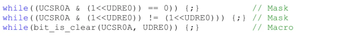
There are several possibilities to implement a while-loop such as used in Code snippet 7. These are shown in Code snippet 8. All of these expressions make sure that only the bit of interest is logically compared. The third possibility shows the most abstract way to wait while a bit is clear by means of a macro. This way enhances readability and is used when there is no need for students to exactly know how these expressions evaluate.
Code snippet 8. Alternative implementations for waiting until exactly one bit is logic one in a register. while((UCSR0A & (1<<UDRE0)) == 0)) {;} // Mask while((UCSR0A & (1<<UDRE0)) != (1<<UDRE0))) {;} // Mask while(bit_is_clear(UCSR0A, UDRE0)) {;} // Macro
2.2
Teaching methods
The code snippets in the previous section show that bitwise and logic operators are a key factor in I/O programming for microcontrollers. The way these operators are used is specific for the domain of microcontroller programming. For instance, a while-loop with an empty body that waits for a logical change of a bit in a hardware register, is a technique that is not relevant to other programming domains. Within microcontroller programming education, these programming techniques are explicitly taught. The book about microcontroller basics by Davies (2008) for example, only discusses the important aspects of C for embedded system. These aspects are declarations, shifts, low-level logic operations, masks to test and modify individual bits, bitfields, and unions. These aspects are explained by simple examples. Dolman (2010) uses a visualisation technique, as depicted in Figure 3, to explain the step-by-step evaluation of composite expressions. The expression explained in Figure 3 is:
PORTB = (PORTB & 0xF9) | ((x << 1) & 0x06);
Figure 3. Visualisation technique used by Dolman to explain the evaluation of a composite expression (Dolman, 2010).
2 MICROCONTROLLER TEACHING 9
Pardue (2005) uses a similar visualisation technique to explain the evaluation of single bitwise and logic operators. He uses a discussion to explain the evaluation of composite expressions, such as the following condition in an if-statement:
if( !(TCC0RA & WGM01) && !(TCC0RA & WGM00) ) … Such an expression is explained by the following discussion:
“The (TCC0RA & WGM01) test will be 1, true, only if the WGM01 bit is 1, likewise for the (TCC0RA & WGM00) statement. The !(TCC0RA & WGM01), adding the ‘!’ or NOT to the statement means that it is true only if the innards of the () are false. The ‘if’ statement will only be true if both the first and (logical AND = &&) the second are true. So we’ve used two AND in this statement.”
Pardue notes that if this explanation is not clear, the reader should “… get out the pencil and paper computer and work through it till it is.”, emphasising the importance of understanding the step-by-step evaluation of such statements.
There are dozens of teaching methods that instructors can use in their classes for teaching bitwise and logic operators, such as lectures, individual and group reports, textbook assignments, laboratory experiments, blended learning, etcetera. According to Gilibert et al. (2006) the best way to introduce microcontrollers is by practical exercises and to avoid theoretical explanations. To overcome the drawbacks related with the availability of laboratory resources, they implemented a “remote microprocessor work bench”. This system allows students to remotely debug their code and interact with the hardware.
Besides practical exercises, personal feedback in an early stage and progress tracking is important. For this purpose, Weiss et al. (2005) assign one senior student to five students for one hour each week in a microcontroller course. They found that these senior students “have a tremendous influence on the motivation and performance of the students and are in fact the pivotal factor in determining the motivational impact of a course”. To overcome the drawback of planned sessions they suggest to make tutoring available with the use of a webcam. They note that distance learning will also benefit from such an approach.
2.3
Expression evaluation
Learning how to develop software for microcontrollers does not only concern the bottom-up creation of programs. It also involves understanding how expressions evaluate, which is a top-down approach. This section presents two expressions and how these expressions evaluate to a unique representation that cannot be evaluated any further, also known as the normal form. The first expression will be the running example throughout the rest of this document.
10 2 MICROCONTROLLER TEACHING
Expression 1
while(!(UCSR0A & (1 << UDRE0))) {;}
A possible first evaluation step is substituting the definition UDRE0. For the ATmega328P microcontroller, UDRE0 is defined as the decimal value 5.
Substitute definition UDRE0 while(!(UCSR0A & (1 << 5))) {;}
A possible next evaluation step is the bitwise left shift operator. The expression (1<<5) yields 32. However, when the left operand of the bitwise shift left operator is in binary representation, it is clearer how the bitwise shift left operator evaluates. Therefore, before bitwise left shifting, the left operand is first converted to its binary representation.
Decimal to binary
while(!(UCSR0A & (0b00000001 << 5))) {;} Bitwise left shift
while(!(UCSR0A & 0b00100000)) {;}
From this point, further evaluation depends on the value of the bits in register UCSR0A. This is a volatile memory location, which means that the actual value can change at any moment in time. For instance, if UCSR0A is equal to 2, then the evaluation continues as follows:
Substitute register contents (e.g. 2 in binary representation) while(!(0b00000010 & 0b00010000)) {;}
For evaluation of the bitwise and operator, binary representation for both operands is most convenient. In this example both operands are already in binary representation, therefore no evaluation step is needed to transform either of the operands.
Bitwise and
while(!(0b00000000)) {;} Finally, there are two more steps:
Substitute numeric by Boolean representation while(!(false)) {;}
Logic negate while(true) {;}
2 MICROCONTROLLER TEACHING 11
The evaluation of this expression could also have started by substituting the contents of UCSR0A. This gives the following possible evaluation:
while(!(UCSR0A & (1<<UDRE0))) {;}
Substitute register contents (e.g. 2 in binary representation) while(!(0b00000010 & (1<<UDRE0))) {;}
Substitute definition UDRE0 (e.g. 5) while(!(0b00000010 & (1<<5))) {;}
Decimal to binary
while(!(0b00000010 & (0b00000001 << 5))) {;} Bitwise left shift
while(!(0b00000010 & 0b00100000)) {;} Bitwise and
while(!(0b00000000)) {;}
Substitute numeric by Boolean representation while(!(false)) {;}
Logic negation while(true) {;}
Both evaluations are correct and there is not a preference for one of them. Expression 2
PORTB = (PORTB & 0xF9) | ((x<<1) & 0x06);
The first evaluation step of this expression would be to substitute the volatile value of register PORTB, the volatile value of the variable x, or both. A possible evaluation is the following:
Substitute register PORTB (e.g. 4) Substitute variable x (e.g. 2)
PORTB = (4 & 0b11111001) | ((2<<1) & 0b00000110); Decimal to binary
PORTB = (4 & 0b11111001) | ((0b00000010<<1) & 0b00000110); Bitwise left shift
PORTB = (4 & 0b11111001) | (0b00000100 & 0b00000110); Bitwise and
12 2 MICROCONTROLLER TEACHING Decimal to binary PORTB = (0b00000100 & 0b11111001) | 0b00000100; Bitwise and PORTB = 0b00000000 | 0b00000100; Bitwise or PORTB = 0b00000100; An alternative evaluation would be:
PORTB = (PORTB & 0b11111001) | ((x<<1) & 0b00000110); Substitute register PORTB (e.g. 4)
Substitute variable x (e.g. 2)
PORTB = (4 & 0b11111001) | ((2<<1) & 0b00000110); Bitwise and
Bitwise shift left
PORTB = 0 | (0b00000100 & 0b00000110); Bitwise and
Bitwise or PORTB = 4;
These examples show that evaluations use a bottom-up strategy, taking precedence and associativity of the operators into account. It also shows that there can be many different ways to evaluate a given expression and that multiple evaluation steps can be taken at once. The number of evaluation steps depends on:
The number of substitutions of registers, variables and definitions.
The number of operators.
The transformation to other number representations for operands, which depends on the operator and the previous evaluation steps.
Definitions that might contain composite expressions.
The steps a student combines into one evaluation step.
Although the same expression can be rewritten in many different ways, it should always yield the same normal form. A rewriting system for these expressions must therefore be confluent and terminating.
3 RESEARCH ASSIGNMENT 13
R
ESEARCH ASSIGNMENT
There are many ITSs available, especially for programming exercises. The goal of this research project is to investigate how an ITS can be created for learning the evaluation of microcontroller I/O programming expressions, by using the generic framework from the interactive domain-specific exercise assistants (IDEAS) project. The framework provided by the IDEAS project can be used for developing domain- specific reasoners. A domain reasoner is a software program that helps students solve exercises for a specific problem domain. The IDEAS project was started by a group from the Faculty of Computer Science of the Open University of the Netherlands and the Department of Information and Computing Sciences of Utrecht University. Section 3.1 formulates the research questions. The research method is described in Section 3.2. Finally, the research scope is discussed in Section 3.3.
3.1
Research questions
Section 2 describes characteristic challenges for teaching microcontroller I/O programming. Students not only need to learn the syntax and semantics of a programming language, they also need to acquire knowledge and skills related to I/O programming for different microcontrollers, such as manipulating bits at specific I/O locations and using loops to wait for a logical change of a specific bit. The evaluation of these composite expressions can be hard to comprehend for novice embedded systems engineers. Most ITSs for programming would address such a task bottom-up, by giving feedback and hints with the goal of guiding students towards a solution. It is also valuable for students to learn the top-down evaluation and interpretation of complex expressions, which is also recognized by Kumar (2005). Another characteristic for the domain of microcontroller I/O programming is the diversity of libraries and programming languages. An ITS for this domain should be capable of handling this diversity, rather than the need to create separate tutoring systems for each difference.
These observations narrow down the research question to the following: HOW TO SUPPORT MULTIPLE MICROCONTROLLERS WITHIN AN INTELLIGENT TUTORING SYSTEM THAT HELPS STUDENTS TO UNDERSTAND THE EVALUATION OF I/O PROGRAMMING EXPRESSIONS?
An answer can be formulated after answering these sub-questions:
i. How can feedback and hints be generated from a student expression, an exercise and instructor feedback using the IDEAS framework?
14 3 RESEARCH ASSIGNMENT
iii. How can multiple imperative programming languages be supported?
iv. What types of feedback and hints help students to understand the evaluation of microcontroller I/O programming expressions?
v. What are differences and similarities between this tutor for learning the evaluation of microcontroller I/O programming expressions and existing programming tutors?
The answers to these research questions in formulated in Section 9.
3.2
Research method
This section describes what research methods are used to answer and validate each sub-question listed in Section 3.1.
Literature and tutorials2 for implementing a domain reasoner using the IDEAS framework are studied to formulate an answer to sub-question i. This information is used to conduct an experiment. A first prototype of a domain reasoner is implemented with static support for expressions. No front-end is created for providing a graphical user interface. The calculated evaluations and feedback generation are validated by a demonstration and a code walkthrough with the supervisor.
For answering sub-questions ii and iii, the outcome of the experiment of sub-question i is used as a starting point for a new experiment. A new domain reasoner is implemented and tested. A simple web-based front-end is created for the purpose of validating the prototype. Students and colleagues are asked to use the prototype, and fill in a questionnaire, which is used to validate the calculated evaluations. It is expected that the IDEAS framework can be used for creating an ITS that supports multiple microcontroller definitions and programming languages. The answer to sub-questions i to iii is described in Section 5. The validation with students and colleagues is described in Section 6.
The categories for feedback generation for learning programming, as described by Keuning et al. (2016), are used to formulate an answer to sub-question iv. It is expected that the types of feedback that guide students step-by-step will help students in their learning process. The answer to this sub-question is formulated in Section 5 and validated in Section 6.
The comprehensive list of tools for learning programming, as identified by Gómez-Albarrán (2005), and a literature study are used to formulate an answer to sub-question v. It is expected that there are not many ITSs for the purpose of expression evaluation. The answer is formulated in Section 7.
3 RESEARCH ASSIGNMENT 15
3.3
Research scope
The prototype created for this research project is a tutoring system that can be used to learn the evaluation of single expressions at a specific moment in time. It is not a tutor for the bottom-up creation of programming algorithms. The scope of the research project is limited to two typical I/O programming tasks. The first task is looping until a bit is set. For example:
while(!(UCSR0A & (1<<UDRE0))) {;}
The second task is assigning specific bits of a variable (x) to an output register while making sure the other bits in this register do not change. For example:
PORTB = (PORTB & 249) | ((x << 1) & 6);
The only supported task is rewriting an imperative expression step-by-step to its normal form. Although software for microcontrollers can be written in many programming languages, two imperative languages are supported. Style issues are out of scope. The prototype provides a means to cope with volatile data, such as registers and variables. Furthermore, the prototype enables instructors to customize the tutoring environment for at least two different microcontrollers: the ATmega328P and the STM32F051R8.
Finally, the prototype will not decide on which task a student should do next. Students can select an expression from a menu or manually enter an expression.
4 EXAMPLE SESSION 17
E
XAMPLE SESSION
This section demonstrates the tutoring system prototype. The tutoring system is called MicK, which is an abbreviation for Microcontroller Knowledge. It uses a web application front-end for student interaction. Section 4.1 introduces the web application and describes typical student interactions. The customization options are described in Section 4.2.
4.1
Student interaction
A typical session by a hypothetical student starts with opening the web application in a web browser. The interface as depicted in Figure 4 is presented. The student starts by selecting a microcontroller and programming language from the first dropdown box. Upon selection, relevant example expressions are automatically added to the second dropdown box. The student either selects an example expression and optionally changes it, or manually enters an initial expression in the input field below the Start button.
18 4 EXAMPLE SESSION
Let us assume that the student selects the following expression from the examples and does not change it:
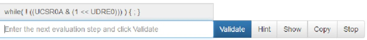
while( ! ((UCSR0A & (1 << UDRE0))) ) { ; }
A tutoring task is then started by clicking the Start button. The tutoring system analyses this initial expression and presents a value for the register UCSR0A and the definition UDRE0:
Value of definitions, registers and volatile variables for this microcontroller and programming language:
UCSR0A = 0b00001111 UDRE0 = 5
At this point, all information required to do an evaluation task is available for the student. An additional input field is presented for the student to enter the next evaluation step, as depicted in Figure 5.
Figure 5. After pressing the Start button, the student is asked to enter the next evaluation step.
The student copies the expression by clicking the Copy button. The copied expression is then edited by the student by substituting both the register and definition:
while( ! ((0b00001111 & (1 << 5))) ) { ; }
The student validates this evaluation step by clicking the Validate button. The tutor responds with the message:
That is correct.
Another input field is added to the list of evaluation steps, which allows the student to enter the next evaluation step. The student enters the next step by removing the redundant parentheses and evaluating the shift left operator, but makes a common mistake by reversing the order of operands of the shift left operator:
while( ! (0b00001111 & 10) ) { ; }
The student clicks the Validate button and the tutor responds with the message: That is incorrect. The operands of the shift left operator are reversed
This message tells the student exactly what went wrong. By clicking the hyperlink shift left, a new window is opened with an external website that explains the shift left operator.
4 EXAMPLE SESSION 19
The student does not know how to proceed and clicks the Hint button. The tutor clears the incorrect input field and responds with the message:
1
=> rewrite this decimal number to its binary representation
This message tells the student which operation must be performed on which part of the subexpression (1 << 5). Again, the hyperlink points to an external website for more information about the operation.
Let us assume that the student still does not know how to proceed and clicks the Show button. The tutor responds with the message:
1
=> rewrite this decimal number to its binary representation 0b00000001
For the most part, this is the same message as when the student requested a hint. The tutor now, however, also fills in the solution:
while( ! ((0b00001111 & (0b00000001 << 5))) ) { ; } The student clicks Validate and the tutor responds with the message:
That is correct.
Now the student makes a mistake by entering and validating the following expression:
while( ! (0b00001111 & 0) ) { ; } The tutor responds with the message:
Although the expressions are equivalent, you took a wrong step.
This message tells the student that the submitted expression evaluates to the same normal form, but the part that was rewritten is incorrect. This expression is not a valid evaluation step, and therefore no new input field will be added to the evaluation list. The student might edit the expression, or request a hint, or request the solution to this step. Let us assume the student changes the expression to:
while( ! (0b00001111 & 0b00100000) ) { ; }
The student clicks the Validate button and the tutor responds with the message: That is correct.
The student now tries to take multiple steps at once, but forgets a closing parenthesis: while( ! (false ) { ; }
20 4 EXAMPLE SESSION
Syntax error 1:1: unexpected 'w'
expecting '(', ')', '{', end of input, or operator The student corrects the mistake:
while( ! (false) ) { ; }
The student clicks the Validate button and the tutor responds with the message: That is correct.
The student enters the final step: while( true ) { ; }
The student clicks the Validate button and the tutor responds with the message: That is correct.
You have finished the task successfully!
This message tells the student that the expression is in a normal form. The input field with the final solution is marked green and no new input field is added to the evaluation list. The complete worked out solution as seen by the student is depicted in Figure 6. By clicking the Stop button, the task stops and the student can start a new task.
4 EXAMPLE SESSION 21
4.2
Instructor interaction
Instructors can customize the tutoring system by adding or modifying configuration files, which are read from the filesystem. Each configuration file is interpreted as a new exercise. An exercise must be created for the combination of a microcontroller and a programming language. All these exercises are automatically added to the list the student can choose from in the web application. For changes to take effect, the client only needs to reload the web application.
An example exercise configuration file is provided in Appendix A. Each exercise consists of the following configuration options:
Exercise id
This must be a unique combination of a microcontroller and programming language represented as a string, such as ‘ATmega328P’ and ‘ANSI-C’. These two strings are concatenated when presented in the dropdown box in the web application.
Word length
The number of bits of the architecture for the selected microcontroller. Numbers that are displayed in the binary or hexadecimal number representation will use this configuration option to determine the number of digits for zero padding.
Programming language file
Instructors can change the programming language by specifying language specific keywords and tokens in a language definition file. The path to this file must be specified in the configuration file. The language specification can be reused amongst exercises. An example of a customizable token is the assignment operator. It might for instance be specified as the string “=”, or as the string “:=”. Two example language definition files are provided in Appendix B.
Definition files
The back-end allows microcontroller specific definitions to be added in different file formats. This allows for easy integration of existing definition files that are often provided by microcontroller vendors. When, for instance, the ANSI-C programming language is used, the instructor specifies the path to one or more C header files. All definitions from these files are then automatically parsed and available for substitution.
Script file
The feedback and hint messages provided by the tutoring system can be specified in a script file. This enables instructors to easily change feedback and hint messages, for instance to match classroom lectures, or support multiple languages. An example script file is provided in Appendix C.
22 4 EXAMPLE SESSION Examples
Zero or more example expressions can be specified that will appear in the examples dropdown box in the web application.
Initial values for volatile variables and registers
In the event that registers or volatile variables are used in an expression, they must have an initial value for evaluation. These initial values are not randomly generated, but must be provided by the instructor. This improves the ability to steer the students’ learning process. The initial values are interpreted as subexpressions. Some examples of initial values are:
o 15 o 0x000F o 0b00001111 o 1 << 5
5 AN ITS FOR MICROCONTROLLER I/O PROGRAMMING 23
A
N
ITS
FOR MICROCONTROLLER
I/O
PROGRAMMING
The ITS prototype created for this research project consists of two major building blocks: a front-end and a back-end. Their dependencies are depicted in Figure 7. The front-end interacts with the user. It filters user input and presents information. For this project, the front-end is realized as a web application. The design decisions and implementation examples for the front-end are described in Section 5.1. The back-end implements the functionality to reason about a problem domain. The IDEAS framework is used for this purpose. The design decisions and implementation examples are described in Section 5.2. Special considerations have been taken for diagnosing expressions for the domain of microcontroller I/O programming. These considerations are described in Section 5.3.
Figure 7. The building blocks of the ITS prototype.
5.1
Web application
The web application is implemented using Bootstrap, JQuery and JavaScript. The look-and-feel is described in Section 4.1.
5.1.1
Model-View-Controller
The web application is implemented using the model view controller (MVC) design pattern. This pattern is depicted in Figure 7. As soon as the controller is triggered by
Log db Configuration files M IDEAS framework Domain reasoner C V Student Back-end Front-end viewUpdate() modelRequest() requestToDR() responseFromDR() Exercises Feedback Services
24 5 AN ITS FOR MICROCONTROLLER I/O PROGRAMMING
the student, the controller creates an object in the JavaScript object notation (JSON) and calls the model’s modelRequest()function with this object as a parameter. The model holds an abstract representation of the data. It has no intelligence, because it uses the domain reasoner for this purpose. This is transparent for both controller and view. Another JSON formatted object is created by the model and the function requestToDR() is used to transmit the request to the domain reasoner.
The model receives the response from the domain reasoner in the callback function responseFromDR(). The response is also formatted using JSON. The model extracts the information from the object, interprets it, creates a new JSON formatted object and calls theviewUpdate() function, which updates all available views with this new object as a parameter. As soon as a view receives such an object, it knows how to display the information, or flushes it.
5.1.2
Data logging
Logging is enabled in the back-end for investigating interactions. For this purpose, the front-end creates a random user id. This id is stored in a cookie that expires after one day. When requesting specific services from the domain reasoner, such as the create service, the domain reasoner provides a session id that can be used as a token during the remainder of a session to easily filter related interactions from the logging database. Data is logged in an SQL database. Local sqlite3 logging for Windows is enabled by building the HDBC-sqlite33 package and rebuilding the IDEAS framework with logging enabled.
5.2
Domain reasoner
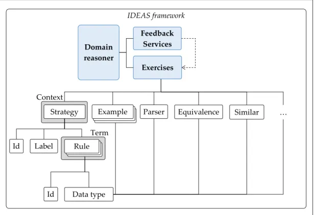
The front-end requests a stateless service from the domain reasoner, such as a list of exercises. For providing these services, the domain reasoner consists of two building blocks, as depicted in Figure 7. The first building block is called feedback services. These are already implemented by the framework and use the abstract interfaces of the other building block called exercises. These exercises consist of several components that a developer of a domain reasoner implements in the functional programming language Haskell using the IDEAS package4. The most important components of an exercise are depicted in Figure 8. This figure shows the hierarchy of the building blocks and their dependencies. A data type must be defined for domain-specific expressions. Rules define how the data type can be transformed. An id is used for identification. Many entities within the IDEAS framework can have such an id, although Figure 8 only shows this for rules and strategies. It is also possible to define buggy rules to recognize commonly made mistakes. A rule is translated to the term data type, which allows the use of a zipper for traversal. Simple exercises can be solved by just applying rules. More complex exercises must be solved
3 https://hackage.haskell.org/package/HDBC-sqlite3, January 2017. 4 http://hackage.haskell.org/package/ideas, November 2016.
5 AN ITS FOR MICROCONTROLLER I/O PROGRAMMING 25
by combining rules into a procedure, which is called a strategy. A label gives the opportunity to provide localized feedback messages.
Figure 8. Several components of an exercise and their dependencies.
There are also, among others, the following components (Heeren & Jeuring, 2014):
Zero or more example expressions.
A parser to parse a human readable string to the domain specific data type.
A pretty printer to print the domain specific data type into a human readable string.
An equivalence function to test whether two expressions are semantically equivalent.
A similarity function to test whether two expressions are syntactically the same, or nearly so.
A goal predicate to test whether an expression is in a solved form.
The following sections describe the implementation of these and other components and the rationale for design decisions.
5.2.1
Data type for I/O programming expressions
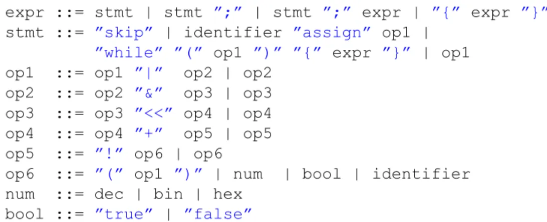
A data type is used for abstract representation of domain-specific expressions. The data type for this domain is related to the grammar of typical microcontroller I/O programming expressions. The grammar implemented in the prototype is as follows:
IDEAS framework Context Equivalence Similar Parser Example Term … Id Label Data type Strategy Rule Rule Rule Id Domain reasoner Exercises Feedback Services
26 5 AN ITS FOR MICROCONTROLLER I/O PROGRAMMING
expr ::= stmt | stmt ”;” | stmt ”;” expr | ”{” expr ”}” stmt ::= ”skip” | identifier ”assign” op1 |
”while” ”(” op1 ”)” ”{” expr ”}” | op1 op1 ::= op1 ”|” op2 | op2
op2 ::= op2 ”&” op3 | op3 op3 ::= op3 ”<<” op4 | op4 op4 ::= op4 ”+” op5 | op5 op5 ::= ”!” op6 | op6
op6 ::= ”(” op1 ”)” | num | bool | identifier num ::= dec | bin | hex
bool ::= ”true” | ”false”
The starting non-terminal of an expression is expr. Expr is a statement optionally followed by a semicolon. Expr is optionally placed between braces. Although the grammar allows a sequence of expressions to be parsed separated by a semicolon, the prototype does not support the evaluation of such a sequence of expressions.
The grammar supports four statements:
Skip: represents an empty statement.
Assignment: assign the result of an operation to an identifier.
While: looping structure with a condition between parentheses and a body between braces.
Op1: an operation with no side-effect. Although such a statement would not make sense in a programming language, the prototype uses such a statement for parsing definitions.
Figure 9. Parse tree for the expression while(!(UCSR0A & (1<<UDRE0))){;}, showing only the terminal and non-terminal symbols.
While Prefix “Skip” “UCSR0A” “!” Infix Var Infix “&” 1 Dec “<<” Var “UDRE0” Expr
5 AN ITS FOR MICROCONTROLLER I/O PROGRAMMING 27
Infix operators are left associative. The grammar is not ambiguous, because of the operator precedence.
The num terminal symbols are numerical values in the decimal (dec), binary (bin) or hexadecimal (hex) number representation. An identifier is a string that starts with a letter followed by zero or more alpha numerical characters.
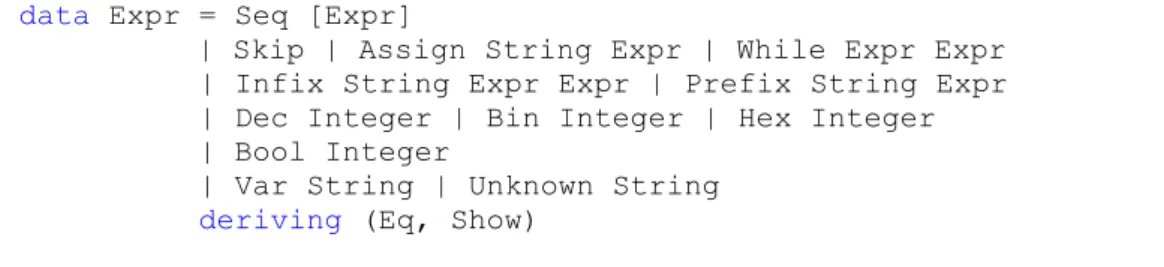
The parse tree, showing only the terminal and non-terminal symbols, for the expression while(!(UCSR0A & (1<<UDRE0))){;} is presented in Figure 9. Sentences belonging to this grammar are parsed to an abstract syntax, which is represented by the data type as shown in Code snippet 9. A sequence of expressions is represented as a list. The left-hand side of an assignment is a string, although most programming languages would also allow expressions in the left-hand side of an assignment.
Code snippet 9. Data type for expressions. data Expr = Seq [Expr]
| Skip | Assign String Expr | While Expr Expr | Infix String Expr Expr | Prefix String Expr | Dec Integer | Bin Integer | Hex Integer | Bool Integer
| Var String | Unknown String deriving (Eq, Show)
The operator of infix and prefix expressions is represented as a string. This allows to easily add more operators and support for programming language specific tokens. The numerical values Dec, Bin and Hex are internally represented as integers. A Bool is also represented as an integer. This allows for calculation and comparison between numerical and Boolean values without the need of conversions. The parser converts “false” to the integer value 0 and “true” to the integer value 1.
Figure 10. Simplified AST for the expression while(!(UCSR0A & (1<<UDRE0))){;}.
While ! Skip “UCSR0A” & 1 << “UDRE0”
28 5 AN ITS FOR MICROCONTROLLER I/O PROGRAMMING
All identifiers other than the identifier in the left-hand side of an assignment, are assigned the Var constructor. This distinction is made, because for typical microcontroller I/O programming expressions the identifiers in the left-hand side of an assignment will not be substituted. If an identifier with the Var constructor cannot be substituted, the constructor is changed to Unknown.
The simplified AST in Figure 10 illustrates the result after parsing for the expression
while(!(UCSR0A & (1<<UDRE0))){;}.
The parser is implemented using the monadic parser combinator library megaparsec5. One particular advantage of this library is the support for well-typed error messages instead of string-based error messages, which provides flexibility in describing parse errors. This helps students to analyse the syntactic mistakes made when submitting expressions. The type declaration of the parser is shown in Code snippet 10. It takes a language definition and a string as an argument, and either returns a string with a syntax error message or an expression. A language definition is a mapping of programming language specific keywords to the keywords used by the parser. A detailed description of language definition is provided in Section 5.2.4. A pretty printer turns an expression into a human readable string. The prototype pattern matches on the classifications of the data type and does not remove redundant parenthesis. The pretty printer takes the word length of the selected microcontroller into account, which is provided as a setting in the configuration file as discussed in Section 5.2.2, for zero padding numbers in the binary and hexadecimal representation. The function’s type declaration is shown in Code snippet 10.
Code snippet 10. Type declarations for the parser and pretty printer.
parseStringM :: LanguageDef -> String -> Either String Expr ppExpr :: LanguageDef -> Expr -> String
5.2.2
Customizable exercises
Each microcontroller and programming language pair have distinct configurations for an exercise. These configurations are:
A unique exercise identifier
The microcontroller’s word length
One or more microcontroller definition files
One programming language definition file
One script file
Example expressions
Initial values for volatile data, such as registers and variables
5 AN ITS FOR MICROCONTROLLER I/O PROGRAMMING 29
For each exercise, these configurations must be provided in a separate configuration file in the XML format. Exercises are dynamically generated for each configuration file, by parsing all XML files from the exercises folder at start-up of the domain reasoner as depicted in Figure 11. From each exercise configuration file, the exercise parser determines which other files are required. This means that the exercises folder is the only hard coded file location in the domain reasoner. An example exercise configuration file is shown in Appendix A.
Dynamically generating exercises allows instructors to easily add new exercises or update existing exercises. There is no need for programming or recompiling the domain reasoner.
Figure 11. Configuration files from the Exercises folder are parsed and exercises are dynamically generated.
5.2.3
Parsing microcontroller definitions
Definitions supported by a microcontroller must also be supported by the domain reasoner. The prototype assumes that a definition consists of a keyword, which is a string, and a value, which is an expression. All of these keyword and value pairs are internally represented in a list, which is called an environment.
Microcontroller definitions are often provided in header files. To make support for these definitions as easy as possible for instructors, the domain reasoner is capable of parsing several definition file formats. This is depicted in Figure 12. The prototype supports C header files, but does not support macro expansion. There is also support for a custom file format called DEF, which parses definitions with the following syntax:
DEF <identifier> <value> <newline>
IDEAS framework Exercise Exercises Domain reasoner Exercise Feedback Services Exercise parser & generator DEF XML
Definitions
Scripts
Exercises
Languages
30 5 AN ITS FOR MICROCONTROLLER I/O PROGRAMMING
This custom format allows instructors to add support for unsupported file formats. It requires a one-time translation from the original format to the DEF format.
Each exercise has its own environment. In the configuration file for an exercise, the instructor provides the paths to zero or more definition files and for each definition file the type of parser to use.
Figure 12. Parsers for the definition files and the internal representation for each exercise.
5.2.4
Parsing language definitions
Support for multiple imperative programming languages is realized by allowing instructors to customize keywords and tokens from the grammar as discussed in Section 5.2.1. Typical expressions for microcontroller I/O programming do not require differentiation in the abstract syntax. The customizable tokens are:
“while”
“assign”
“true”
“false”
Instructors can supply a language definition in XML format. Two example definition files are presented in Appendix B. For these two examples, the expressions shown in Code snippet 11 are semantically the same.
Code snippet 11. Support for custom keywords and operators. while(!(True)) {;} ZOLANG(!(WAAR)) {;} IDEAS framework Exercise Exercise Domain reasoner Exercise Feedback Services DEF H Parser Internal representation type Env=[(String,Expr)] H PHP DEF DEF Other DEF Parser
5 AN ITS FOR MICROCONTROLLER I/O PROGRAMMING 31
The language definition parser creates an environment for each exercise, in a similar way the parser for microcontroller definitions creates an environment. The result is a list of keyword and value pairs, both represented as a string. This language definition environment is used for parsing and pretty printing expressions.
5.2.5
Rules
Rules define how values of the data type can be transformed. Generally speaking, a rule takes a name and a function of type a -> Maybe a as its arguments. If a rule can be applied, the rule returns Just the transformed expression. If a rule cannot be applied, the rule returns Nothing.
The prototype implements four groups of rules. The first group are rules for operators that transform expressions. For each operator, a similar rule is defined as given in Code snippet 12. In this example, both operands of the bitwise and operator must be of constructor Bin, because it is more illustrative to perform this operation on numbers in binary representation. The result is a new expression represented as a binary number with the value being the result of the bitwise and operation.
Code snippet 12. Rule for the bitwise and operator. -- |Rule to bitwise-and two numbers
bitwiseAndRule :: Rule Expr
bitwiseAndRule = describe "Bitwise and two numbers" $ makeRule "rule.bitwiseand" f
where
f :: Expr -> Maybe Expr
f (Infix "&" (Bin x) (Bin y)) = Just $ Bin (x Bits..&. y) f _ = Nothing
The second group of rules are transformations to other number representations, such as conversions to decimal, binary, hexadecimal, and Boolean. Code snippet 13 shows a rule for converting a decimal number to a binary number. It changes the constructor, which is used by the pretty printer for representation. This allows the internal representation for all number representations to be the same, namely of type Integer.
Code snippet 13. Rule for converting a number from decimal to binary representation. -- |Rule to convert a decimal to binary
decToBinRule :: Rule Expr
decToBinRule = describe "Decimal to binary" $ makeRule "rule.dectobin" f
where
f :: Expr -> Maybe Expr f (Dec x) = Just $ Bin x f _ = Nothing
32 5 AN ITS FOR MICROCONTROLLER I/O PROGRAMMING
The third group is a substitution rule that is shown in Code snippet 14. This rule transforms a definition, a register, or a variable, all represented by the Var constructor, into an exercise-specific expression. The rule therefore takes an environment, as discussed in Section 5.2.3, as an argument. The lookup function is used to search the environment for a substitution. If a substitution cannot be found, the lookup function returns Nothing. In such a case, the rule returns the same value (x), but changes the constructor to Unknown.
Code snippet 14. Rule for substituting definitions and variables.
-- |Rule to substitute definitions and variables
substituteRule :: Env -> Rule Expr substituteRule env = describe
"Substitute a definition or a variable" $ makeRule "rule.substitute" f
where
f :: Expr -> Maybe Expr
f (Var x) = Just $ fromMaybe (Unknown x) (lookup x env) f _ = Nothing
The fourth and final group are buggy rules. The prototype implements one buggy rule that is shown in Code snippet 15. This rule describes the transformation of the shift left operator when the operands are reversed. This common mistake is made when both operands are in decimal representation.
Code snippet 15. Buggy rule for the shift left operator.
-- |Reverse the operands of the shift left operator
shiftLeftBuggy:: Rule Expr
shiftLeftBuggy = describe "Shift left operands reversed" $ buggyRule "rule.buggy.shiftleft" f
where
f :: Expr -> Maybe Expr
f (Infix "<<" (Dec x) (Dec y)) =
Just $ Dec (y `Bits.shiftL` fromIntegral x) f _ = Nothing
5.2.6
Strategies
Strategies combine rules to solve more complex exercises. Strategies must be provided in an embedded domain-specific language (EDSL) that is interpreted by the IDEAS framework as a context-free grammar. Strategies are used to calculate feedback messages given an exercise, the strategy for solving it, and student input (Heeren et al., 2010).
A strategy can be composed out of rules, but also out of other strategies. Strategies are combined by using strategy combinators. An example is the choice combinator (.|.), which chooses between two strategies. The prototype implements two