Aging in Place: Fall Detection and Localization in a
Distributed Smart Camera Network
Adam Williams, Deepak Ganesan, and Allen Hanson
Department of Computer ScienceUniversity of Massachusetts Amherst, MA 01003
{apw, dganesan, hanson}@cs.umass.edu
ABSTRACT
This paper presents the design, implementation and evalua-tion of a distributed network of smart cameras whose func-tion is to detect and localize falls, an important applicafunc-tion in elderly living environments. A network of overlapping smart cameras uses a decentralized procedure for comput-ing inter-image homographies that allows the location of a fall to be reported in 2D world coordinates by calibrating only one camera. Also, we propose a joint routing and ho-mography transformation scheme for multi-hop localization that yields localization errors of less than 2 feet using very low resolution images. Our goal is to demonstrate that such a distributed low-power system can perform adequately in this and related applications. A prototype implementation is given for low-power Agilent/UCLA Cyclops cameras run-ning on the Crossbow MICAz platform. We demonstrate the effectiveness of the fall detection as well as the precision of the localization using a simulation of our sample imple-mentation.
Categories and Subject Descriptors
C.2.4 [Computer-Communication Networks]: Distributed Systems; C.3 [Special-Purpose and Application-Based Systems]: Real-time and embedded systems
General Terms
Algorithms, Design, Performance
Keywords
Camera sensors, Distributed sensor networks, Activity recog-nition, Technology and aging
1.
INTRODUCTION
The growing numbers of elderly individuals in need of sup-port to live in the community will severely test the current services infrastructure. Part of the solution is to develop
Permission to make digital or hard copies of all or part of this work for personal or classroom use is granted without fee provided that copies are not made or distributed for profit or commercial advantage and that copies bear this notice and the full citation on the first page. To copy otherwise, to republish, to post on servers or to redistribute to lists, requires prior specific permission and/or a fee.
MM’07,September 23–28, 2007, Augsburg, Bavaria, Germany. Copyright 2007 ACM 978-1-59593-701-8/07/0009 ...$5.00.
Device Power Features
Cyclops Camera 33mW 128x128, 10fps
PTZ Camera 1W 1024x767, 30fps
MICAz Mote 84mW 7MHz CPU, 4KB RAM
Desktop PC 100W 2GHz CPU, 512MB RAM
Table 1: Power consumption and features of several cameras and platforms. One PC with a PTZ camera requires as much power as several hundred MICAz-Cyclops pairs.
technology to increase the length of time elders can remain at home. The ultimate goal is to “consumerize” these tech-nologies and make it practical and affordable to incorporate them into existing homes and lifestyles.
The deployment of such “aging in place” systems poses a number of application challenges. One of the primary con-cerns of families and caregivers of elderly individuals is quick detection and notification of fall events,i.e. when an elderly person has fallen [15]. This is the case not only due to the obvious, immediate medical attention that a fall may re-quire, but also because frequent falling and instability can be a sign of more serious ailments. Several commercial fall alert products exist such as Life Alert [10] and Health Watch [19]. However, these are on-body wearable units and the user must remember to wear them, which makes them less reli-able since elderly individuals often suffer from memory loss. A second challenge in such systems is to be able to local-ize where the fall occurred, for example, in order to guide a mobile robot to the fall for further diagnoses, to provide information to family members, or to direct the activation of higher-powered cameras if available. Commercial wearable fall detection systems do not enable such a capability.
One possible approach for designing such a system is using distributed smart camera networks. Sensors can be placed throughout an elderly person’s living space to monitor their safety and provide a variety of other services, in a manner similar to modern security systems. While such a solution is attractive, traditional high-resolution camera-based systems are often hard to deploy since they require a hard-wired power source, a high-bandwidth network connection, and one or more PCs (with significant power and bandwidth requirements of their own) to do the processing. Even when it is possible to deploy such a network, it is hard to cover every nook and corner of a house using such large cameras due to occlusions, making such an approach insufficient.
Recent advances in low-power camera sensor networks have opened up the possibility of an alternate approach to designing smart camera networks for elderly homes. The use of low-power cameras with mote-class sensor devices has the potential to provide an ad-hoc deployable, cheap, and reli-able infrastructure for such homes. In addition, since these nodes are small and battery powered, they can be placed in hard to reach places like attics and basements, or other occluded places that cannot be covered by larger cameras.
While low-power smart cameras are an attractive possibil-ity for aging in place applications, the design of such systems poses a number of sensor systems research challenges.
Reliable detection: The first challenge is that falls need to be detected reliably since there may be serious conse-quences of undetected falls. Thus, it is critical that falls are not missed. However, the system can tolerate false positives since these would, at most, result in a phone call from a health care professional or relative to the home of the el-derly, in order to check if there is cause for alarm.
Resource constraints:The second challenge is that tradi-tional vision algorithms used for camera-based fall detection use computationally complex techniques[12][18]. Low-power cameras such as the Cyclops camera (Table 1) do not have the computation capabilities to execute these complex math-ematical tasks. Further, images from low-power cameras are often low fidelity (e.g.: the Cyclops camera has only 128x128 resolution), and the cameras are not well-calibrated, hence traditional vision techniques for fall detection may not be appropriate for them.
Energy Efficiency: Energy consumption is a critical de-sign issue in battery-powered sensor networks. The energy consumption of camera sensor networks depends primarily on two factors: (a) sampling rate of the camera, which needs to be kept low, (b) number of messages transmitted by each camera, which needs to be minimized.
Multi-hop Localization: The final challenge is multi-hop localization using a network of cameras. More accurate lo-calization can enable different kinds of assistance such as mobile robots that can move to the appropriate location in response to the fall detection, and provide a health care pro-fessional with diagnostic information such as a pulse or heart rate.
1.1
Research Contributions
In this paper, we propose an architecture that uses a net-work of extremely low-power smart cameras to automati-cally detect and localize falls. Our work has three key con-tributions:
Our first contribution is alightweightperson detection and fall detection algorithm that executes on a simple 8-bit mi-crocontroller. This detection is performed using simple fea-tures that can be inexpensively extracted from each image, and uses the aspect ratio of the foreground pixels to deter-mine the pose of the person. Our results show that we can provide comparable accuracy to an SVM-based fall detec-tion algorithm run on a PC, under relatively stable lighting conditions.
Our second contribution is alightweightalgorithm for main-taining image homographies between pairs of overlapping cameras. These homographies are automatically constructed
in the background using ground point correspondences ex-tracted from images synchronously sampled from each cam-era in the network every few seconds. Our implementation on Cyclops cameras and Motes shows that these pairwise homographies can be estimated with a mapping error of less than 20 pixels.
Finally we describe a novel joint routing and homogra-phy transformationscheme for multi-hop localization of the fallen person. Localization is performed by routing the loca-tion of a detected fall through the network of homographies to a leader node that has been calibrated to world coor-dinates. This allows the use of many overlapping cameras without the need to manually calibrate each one. The ex-act route to the leader is calculated based on the quality of transformations between cameras rather than simply using the shortest path. We show that we can localize falls to roughly 45-55 cms for a 3-hop transformation using Cyclops cameras.
2.
SYSTEM MODEL
In this section, we describe the system model and how the various components of our systems interact to provide a fall detection and localization framework.
2.1
System Model
Our system is comprised of a single tier of homogenous, battery-powered camera sensor nodes. Each node consists of a camera sensor, an on-board processor with RAM and flash memory, and a radio for wireless communication. We assume the existence of at least one leader node whose cam-era has been calibrated to the world in the sense that there is a known homography between its image coordinates and the world coordinates of the 2D ground plane. We also assume that rest of the nodes in the network have cameras that overlap each other to a degree sufficient to ensure a path from any given node to the leader. In practice the cameras should have at least a few square feet overlap in area likely to see movement. This is a reasonable assumption for any reasonably dense network of cameras. The leader knows its status prior to the network being turned on, but the other nodes do not need prior knowledge of the leader’s identity. In order to conserve the limited battery power, we assume that cameras will sample relatively infrequently, at a rate of no more than 1/5 Hz, and that all image processing must be done locally on the node that captures a given image. In addition, all cameras must sample synchronously due to the requirements of the homography estimation approach used by the system. This synchronization can be achieved by having the leader node broadcast a “snap picture” message at the desired interval. While this does not provide pre-cise synchronization, it is sufficient for this system. Clock synchronization across nodes is not necessary. Nodes are able to communicate with each other using their radio links. There is no centralized communication or processing hub in the system. Note that from this point forward, “node” and “camera” may be used synonymously.
2.2
System Operation
There are three key components to the operation of the system, (a) continuous person detection to detect when a human is present in the field of view of the camera, (b) im-age homography estimation between neighbors, i.e., neigh-bor transformations that will enable each camera to
trans-form a point from its frame of reference to a neighboring camera’s frame of reference, and (b) fall detection and multi-hop localization when a fall event actually occurs.
We first describe the person detection process that oc-curs at each camera. The system uses a simple form of background subtraction to detect the presence of a moving object, which we assume is a human, each time the camera takes a sample. Once a person is detected, features of the foreground pixels can be used both for fall detection as well as for homography construction. The key idea to examine the size and shape of a “blob” of foreground pixels in order to determine a person’s posture. If the aspect ratio i.e. the width of the person divided by height, is below a particular threshold, then it is assumed that the person is upright, else the person is assumed to have fallen.
If an upright person is detected, then the event is fed into a homography component that uses this information to form correspondences with neighboring cameras. Image homog-raphy estimation between pairs of overlapping cameras is the tool that allows a fall to be localized without the need to calibrate most of the cameras. The general technique is to determine a set of point or line correspondences between cameras and use them to estimate the transformation [6]. Image homographies are planar projective mappings, and therefore these correspondence must be restricted to a pla-nar section of the image; in this case the ground plane is used. In order to collect pairs of corresponding points, each camera attempts to determine the location of the contact point between the person’s feet and the ground in the fore-ground pixels (if any exist), and will broadcast this informa-tion to neighboring cameras. If other cameras also saw this contact point at the same time, they can store the point and the corresponding point received from the other camera. Us-ing this information, each camera updates its homography estimate using the normalized Direct Linear Transformation method [5].
If a fall event is detected, then the system needs to lo-calize the event and notify the leader of the event. When a fall is initially detected, its location is known only in the image coordinates of the camera that detected it. However, there is a need to provide location in world coordinates to enable other services that will respond to the fall, such as a mobile robot or more powerful cameras. Since cameras have overlapping fields of view, they can use their homo-graphies to transform the location from their field of view to another camera’s field of view. In other words, there is a sequence of image homographies that can be applied to the original location in order to map it to a neighbor’s image coordinates. This joint routing and transformation
procedure is performed in a hop-by-hop manner from the detection camera to the leader. The node that detects a fall will map the location into a neighbor’s coordinate system and then transmit the location to the neighbor via the radio link. This neighbor will do the same and the process will repeat until the fall’s location reaches the leader, who can map it into world coordinates and send it to some external alert system.
One important question to consider in such a joint routing and transformation scenario is: what routing path should be selected to the leader? While shortest path routing may be a good choice from a network performance perspective, this may not provide the minimum error for homography transformations, and therefore for fall localization. Thus,
there is a need to consider routing metrics that capture the accuracy of transformations in addition to the cost of routing a message. We consider several routing methods based on the estimated error of each transformation in this paper.
3.
SYSTEM DESIGN
The system is designed under an assumption ofvery tight processing and RAM constraints. As a result, simple algo-rithms are preferred over possibly more robust and expensive ones. Our goal is to show that even simple techniques on very low-power devices can be reasonably effective at these tasks. To this end, the design assumes that there will be at most one person moving about the environment at a given time and that lighting conditions will remain fairly stable. Clearly, as processing and energy constraints are loosened, more sophisticated procedures can be implemented that will allow more robust tracking and person detection. Results are provided in the evaluation section that compare these simple algorithms to more sophisticated versions.
3.1
Person Detection
Person detection is the process of determining the parts of an image that are likely to contain a human. This task is particularly challenging when using low resolution devices that must sample at a slower rate than a normal video cam-era. Changes in the scene that occur gradually in real time can cause sudden drastic changes in successive frames when sampling infrequently. In addition, significant changes in lighting conditions or static objects being moved around can create foreground noise that persists until the background model is updated. Our approach sacrifices robustness for inexpensive computation, and assumes that the background changes infrequently and abruptly. Thus, if the scene has a large amount of foreground noise for a large number of frames, the background model will be thrown out and built from scratch.
Given these assumptions, we use a simple form of back-ground subtraction to detect the presence of a moving ob-ject, which we assume is a human, each time the camera takes a sample. A mean background image is computed from an initial set of images captured by each camera. This background image is subtracted from each new frame, and pixels are classified as foreground or background based on a single difference threshold. If there is a large enough blob of foreground pixels, it is assumed to be a person. Once a per-son is detected, the system would like to know the contact point of their feet with the ground to facilitate homography estimation. The contact point is estimated by finding the largest column of foreground pixels and selecting the fore-ground pixel in that column that is closest to the bottom of the image. A contact point estimate will be thrown out if the foreground pixels cover more than half the image, or if the point is within a few pixels of the image’s borders. Shadows and other lighting phenomena that can subtly in-terfere with the background model are the most likely causes of bad estimates that frequently go undetected. Fortunately, the homography estimation is robust enough to deal with a few errant points.
3.2
Homography Estimation
Planar homography estimation is a very well studied prob-lem, and many estimation techniques exist using points, lines, curves, texture, etc. along with a least-squares or
RANSAC-based fitting procedure[2]. This is the one pro-cedure where robustness is favored over speed or simplicity, given its importance to the system and the relative infre-quency with which it needs to run. One of the most popu-lar methods is the normalized Direct Linear Transform sug-gested by Hartley[5]. This method requires 4 or more point correspondences between the two images of interest. These points are gathered by detecting contact points as described in the previous section. Whenever a node detects such a point, it broadcasts it to the rest of the network, along with a time stamp of when the point was seen. Since the image capture is synchronized throughout the network, any node with an overlapping view at that point will also have seen it at the same time. Any such nodes will store the pair of points for use during homography estimation.
Assuming that a node has a set of pointsf={f1, ..., fn} from its own images and another setf ={f1, ..., fn}from another node, the goal is to estimate
H= 0 @ hh1121 hh1222 hh1323 h31 h32 h33 1 A
such that H mapsf tof as well as possible. h33 is a scal-ing parameter that can be selected a priori, so there are a total of 8 unknown parameters of H that must be solved for. Specifically, the goal is to find H such thatfi×Hfi = 0. The full mathematical detail is covered in [2]. The important points are that each point correspondence ends up yielding two equations and therefore only four are needed to solve for H (as long as no three are colinear). However, our noisy correspondence estimates will not produce a very good H unless more points are used. The use of more than four points creates an overdetermined system that can be solved in the least squares sense using singular value decomposi-tion. In addition, a drastic improvement in the estimate can be achieved by normalizing the components of the cor-respondence points to have zero mean and variance of√2[5].
3.3
Fall Detection
For the purposes of this work, a fall is defined as an event that results in a person lying on floor in a position they are unable to quickly recover from. This does not necessarily mean that they are perfectly “flat” on the floor. This defi-nition is consistent with prior work on the topic [12][18][8]. In practice the low sampling rate of the cameras means that they are unlikely to see the fall itself, and the goal becomes to detect the result of the fall, i.e. a person in a prone position on the floor. This is a two-class instance of activity recog-nition, and has been approached with many of the standard tools such as Hidden Markov Models (HMMs)and support vector machines (SVMs) [13] [12][18] [21] While these are effective approaches, they have a major drawback: they re-quire computationally intensive training, and data to train on. The low-power target hardware does not have the re-sources for this, nor is it convenient to collect training data of people falling down. Even some of the more sophisticated fall detection techniques tend to key on one particular fea-ture of a person being monitored. This feafea-ture is their aspect ratio, or the width of the person divided by height. It can easily be extracted from a foreground segmentation, and is a very good way of determining whether a person is upright or in a more horizontal position with a simple threshold. If the aspect ratio is greater than a thresholdα <1, the
per-1
2
3 (Leader)
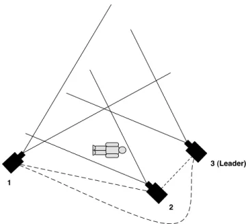
Figure 1: In this scenario, camera 2 detects a fall and needs to route the location to camera 3, the leader. Since cameras 2 and 3 overlap slightly, it is likely that they have a corresponding homography and thus camera 2 could send the location directly to camera 3, effectively using a shortest path approach. However, camera 1 overlaps significantly with both cameras 2 and 3, and therefore could have a much higher quality homography estimate with both cam-eras. So in this case it may be preferable from an error minimization standpoint for camera 2 to send the fall to camera 1, who will then send it to camera 3.
son is probably lying down and may have fallen. Precisely how horizontal a person must be before a fall is detected can be controlled by adjustingα. Decreasingαforces a person to be in more of a horizontal position before it is consid-ered a fall. A value of α= 0.8 is used in our experiments. Obviously there are many situations where a person would purposely be lying down, but it is not unreasonable to as-sume that something may be wrong if an elderly person is lying down close to the floor in a living room or kitchen. At worst, this method is prone to false positives, but as we will show it can perform comparably to a more sophisticated SVM-based procedure.
3.4
Localization
Localization in the system is based on the pairwise cam-era homographies that are automatically estimated by the system. When a fall is detected by a nodenf, its local im-age coordinate is extracted and must be routed to the leader node, which we assume has a manually tuned homography that maps its image coordinates to real world ground plane coordinates. In order to transform the fall’s local coordi-nates to the leader’s image coordicoordi-nates, it must be passed from nf to other nodes that exist along a path of overlap-ping cameras that eventually overlaps with the leader. The fall point is transformed into the destination node’s image
coordinates before every hop, until it reaches the leader and is transformed into world coordinates. An important ques-tion is how to select the best route for a point to travel. It could just choose the shortest path to the leader, but that might not be the best path from an error minimization point of view. Every node can compute a goodness-of-fit measure for any of its homographies, and a point could be routed through a path of least cumulative error. An simple exam-ple scenario where this might be beneficial is illustrated in Figure 1. We compare three different routing metrics in this paper:
• Shortest Path: Points are routed through the net-work along the path consisting of the least number of hops.
• Least Median Error: Distances between nodes are set to be the median squared error of the homography between the nodes. Note that this error is a goodness-of-fit measure calculated from sample points and is not based on any ground truth knowledge. Points are then routed to the leader on the path of least cumulative median error.
• Least Mean Error: This metric is the similar to least median error, but uses mean squared error instead of median squared error.
Up to this point we have assumed that only one camera at a time will detect a fall, but in a dense camera network, this will rarely be the case. Ideally the system would know which cameras provides the best localization estimate for ev-ery point in the scene, but this will never be the case. When multiple fall positions with the same time stamp are received by the leader, it must decide which one to use. A naive pro-cedure would be to simply select one at random. Alterna-tively, estimates from multiple cameras can be combined into a single estimate using some intelligent weighting procedure. We propose that having the leader weigh each estimate by the inverse of the cumulative mean squared transformation error (the same quantity used for the least mean error rout-ing metric) is a simple and effective method for combinrout-ing estimates from multiple cameras. Localization error of this method is compared to that of selecting a random node’s estimate in Section 5.5.
4.
SYSTEM IMPLEMENTATION
This section describes our system implementation using Agilent/UCLA Cyclops [14] cameras, and Crossbow MICAz motes [3] equipped and NAND flash memory boards.
4.1
Camera and Mote Architecture
Our implementation requires two pieces of hardware per node: a Crossbow MICAz mote [3] and a Cyclops smart camera [14]. The Cyclops consists of a Xilinx FPGA, an Agilent ADCM-1700 CMOS sensor, and an ATMega128 mi-crocontroller. The Cyclops camera sensor supports image resolutions of 32x32, 64x64 and 128x128. Image resolution of 128x128 is used in the experimental evaluation. The Cyclops node also has an on-board ATMEL ATmega128L micro-controller, 512 KB external SRAM and 512 KB Flash memory. The Cyclops attaches to the mote via a 32-pin connection and can communicate over the I2C bus. The main feature of the MICAz mote is its 2.4GHz wireless net-working capability and its onboard 512K of flash memory.
MICAz Mote Flash
Cyclops Camera
Send/Recv Points Initiate H Update Update Routing Table Update Point Storage
Point Storage Image Capture People Detection Fall Detection Homography Estimation
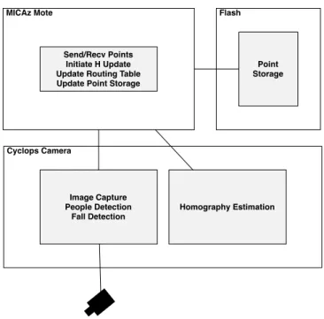
Figure 2: Software architecture overview.
Optionally, each node can also utilize a NAND flash board for additional storage of correspondence points.
4.2
Software Architecture
An overview of the software architecture is shown in Fig-ure 2. The software can be broken down into Cyclops-side and mote-side procedures.
The mote is in charge of sending, receiving and storing points, and commanding the Cyclops to snap an image or perform a homography update. Every 5 seconds, the leader node broadcasts a packet containing a time stamp. Upon receipt, the mote will store the time stamp and send a mes-sage overI2C to the Cyclops, instructing it to snap an im-age. Once the Cyclops has processed the image, it will send a reply back containing the image coordinates of any con-tact point it detected and if a fall occurred, or a null point if there were none. If a valid point is sent from the Cy-clops, the mote will store it in a small memory cache that is dumped to flash every minute. The mote will also broadcast this point and its time stamp to its neighboring nodes. If a fall is detected, the mote checks its routing table for the best path to the leader and sends the fall’s transformed location to the first node on the path. The mote may also receive points from other nodes. When this happens, the mote will temporarily store it in a memory cache. Once per minute, the mote compares the time stamps of all of the points it has received from other nodes to those it collected itself. Any matches will be stored to flash. If enough new matches have been gathered for any pair of cameras, the homography will be updated. To do this, the mote reads each point from flash and sends it to the Cyclops over I2C. When the Cyclops completes the update, it will return the new H to the mote. The mote can continue to receive points while the Cyclops is performing an update, but no new images can be taken locally.
The Cyclops is used for image capture and processing and, due to its faster processor (7MHz) and larger mem-ory (64KB), the resource intensive SVD procedure[1] nec-essary for homography estimation. The Cyclops is set to use grayscale 128x128 images. Color is preferable for back-ground modeling, but there is insufficient memory on the Cyclops for color image use. When initially powered on, the Cyclops will autonomously snap a sequence of 10 images to use for background modeling. Images require 16KB each and are overwritten by the following image. The background model also requires 16KB of memory, as does the foreground pixel estimate for each image. Once the background model is built, the Cyclops waits for the mote to tell it to snap a new image. When it does, it subtracts the image from the background model and thresholds the result to form the foreground estimate. A median filter is run over the fore-ground to remove spurious pixels and the height and width of the resulting blob are measured to test for a fall. The Cyclops also attempts to detect the person’s contact point with the ground. Any contact point or fall detected is sent back to the mote for storage or processing. If an updated H is requested, the Cyclops will receive pairs of points from the mote, which it will transform into the required matrix form and solve using a standard SVD procedure. The resulting H and a goodness-of-fit measure will then be sent back to the mote for use.
5.
EVALUATION
In this section, each of the three primary components of our system are evaluated based on a small experimental in-stallation. The primary areas of interest are the accuracy of the fall detection and the precision of the localization. We are also interested in comparing different route quality mea-sures and their effects on total localization error. In addi-tion, a method for reducing error by combining localization estimates from multiple cameras is suggested and evaluated. Note that we frequently use median error over mean in our experiments. This is due to the fact that when a ho-mography incorrectly maps a point, it has a tendency to do so to the extreme, depending on the exact properties of the mapping and the location of the point. This causes mean er-ror to be skewed upwards in a manner that is not indicative of the true performance of the system.
5.1
Experimental Setup
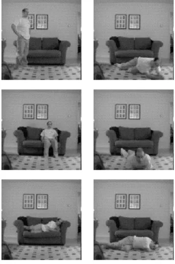
In order to evaluate the system, 6 nodes were placed in an ad hoc manner around the edges of a small room, facing inwards. An effort was made to ensure that each camera had several square feet of overlap with at least one other. Each of the cameras sampled synchronously at 15 Hz for roughly 10 minutes as a single individual walked about the room (see Figure 3) under stable lighting conditions, resulting in approximately 150 samples per camera. These images were stored on a flash board connected to each mote and down-loaded to a PC in order to run our algorithms offline. See Figures 3 and 8 for an illustration of camera placement and sample images. Roughly 20-30 points in each image were hand paired with their corresponding real-world ground lo-cations to provide ground truth for evaluating homography and localization errors. In addition, a total of 40 images were collected from two different rooms, each containing one of four individuals in normal positions (sitting, standing, etc.) or pretending to have fallen. These will be used to evaluate
Camera 2 Camera 1 Camera 3 Camera 4 Camera 5 Camera 6 10' 13'
Figure 3: Floor plan and camera layout in the ex-perimental room. The cameras’ fields-of-view are mostly centered on the 10’x13’ area in the center of the room.
the fall detection procedure. A sample of these images is presented in Figure 9.
5.2
Fall Detection
Accuracy is the primary concern of the fall detection com-ponent. Minimizing the number of false negatives is partic-ularly important, as the consequences of not responding to a fall can be much more serious than responding to a false alarm. To evaluate our fall detection procedure, each image in the 40 image set is classified as “fall” or “no fall” by both the Cyclops’ algorithm as described in Section 3.3 and by a more sophisticated support vector machine (SVM) classifier. The SVM classifier uses a 3rddegree polynomial kernel along with three features: the (x,y) image coordinates of the per-son’s centroid and the aspect ratio, which are extracted from the Cyclops’ images using its background subtraction proce-dure. Since SVM classifiers require training data, leave-one-out testing was employed in order to maximize the useful number of training examples per test. This is not an issue with the Cyclops’ procedure. Table 2 summarizes the re-sults. The Cyclops’ procedure fairs well compared to the SVM-based classifier. Most importantly, no false negatives are produced by the Cyclops’ algorithm. One image that produces a false positive on the Cyclops is shown in the bot-tom left column of Figure 9. Clearly it is caused by a person who is purposely lying down on a couch, which is the type of scenario likely to cause false positives with this procedure. The SVM classifier is able to correctly handle this image due to the fact that it has learned via its training examples that falls do not occur on the couch. A similar affect could be achieved with our system by adding a front end with the ability to specify areas of a room where detected falls should be ignored, although this would have to be done carefully to avoid increasing the likelihood of a false negative.
Method Accuracy False Pos. False Neg.
SVM 97.5% 1 0
Cyclops 95% 2 0
Table 2: Comparison of an SVM-based fall detection procedure with the Cyclops’ method. Each method was tested using a total of 40 images of a person in either a normal position (standing, sitting, etc.) or on the floor as if they had fallen down. The SVM was evaluated using leave-one-out cross-validation.
5.3
Homography Estimation
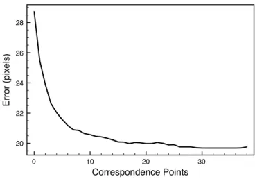
Pairwise image homographies are the basis for localiza-tion in this system, so it is essential to maximize the quality of these mappings. Of course the foundation of this is the detection of corresponding contact points used to construct the estimates, which is a simple but not necessarily very ro-bust procedure. However, the effects of small errors in the correspondences can be mitigated by gathering many such points, which our system does over time in the background. We evaluate the quality of the pairwise homography esti-mates in our system by quantifying the median mapping error in pixels across all pairs of overlapping cameras in the system. For a given number of correspondence points, a random sample of this size is taken from the full set of cor-respondences for a given pair of cameras. The homography between the pair of cameras is estimated using the normal-ized Direct Linear Transform. A collection of points in the image coordinates of the first camera whose image coordi-nates in the second camera are known are transformed using the estimated homography, and the pixel differences between the estimated and ground truth values are computed. This was repeated several hundred times for all pairs of cameras and for each number of correspondence points. The me-dian pixel error across all trials and pairs of cameras for an increasing number of samples is shown in Figure 4. As expected, the error decreases monotonically as the number of samples increases. Overall the median error is roughly 20 pixels when 25 or more correspondences are used, which corresponds to a real world error of roughly 2-3 feet, depend-ing on the camera. As we will see in the next section, this pairwise error is consistent with the total localization error that the system produces.
The best way of improving the homography estimates would be to use a more robust and reliable interest point for correspondences. While the ground contact points are easy to compute, they seldom produce the exact same point on the ground across cameras, and are sensitive to light-ing issues. However, for this system they provide a suitable tradeoff between ease of computation and robustness.
5.4
Multi-hop Localization
Multi-hop localization provides 2D world coordinates of a fall that is visible to the system. While it is desirable to minimize the localization error, it is important to keep in mind that even errors of several feet still provide sufficient information to aid in robot navigation or dispatching other emergency services.
In order to evaluate the quality of the localization in our system, a collection of 20-30 points per camera are mapped through the system into world coordinates and compared
0 10 20 30 Correspondence Points 20 22 24 26 28 Error (pixels)
Figure 4: Median mapping error in pixels across all pairs of cameras as a function of the number of sam-ples in the system used to construct the mappings.
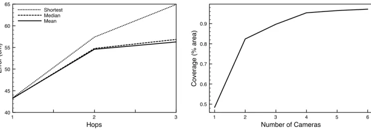
to their ground truth locations. All of the cameras in the experimental setup overlap and all are therefore at most one hop away from the leader. However, we would like to evaluate the accuracy of multi-hop transformations in our system so the camera network topology is restricted in order to create 2 and 3-hop paths to the leader in the network. Cameras are randomly assigned positions in this topology for each of 700 experimental trials. In each trial, the collection of points for each camera is sent through the network using the three different routing metrics presented in Section 3.4 and compared to ground truth. The median error across all trials is computed for each number of hops (in the shortest path sense). The different routing procedures are as follows: Figure 5 shows the results for 1-3 hops. The mean and me-dian metrics noticeably outperform the shortest path met-ric as the number of hops from the node to the leader in-creases. Note that although a node may be only 3 hops from the leader, the mean or median metric might route a point down a longer path to the leader, but the error is still re-duced. Overall the localization error using the mean metric is between 40-55 cm or about 15-22 inches for a 3 hop route, certainly within the limits of a useful localization. While we would expect the error to continue to increase with the number of hops, a suitably dense network of cameras can ensure that the number of hops is kept to a minimum.
5.5
Effects of Camera Density
We would like to know how increasing the number of cam-eras in a scene affects both the total amount of area that is covered as well as the error in areas that are visible from mul-tiple cameras. Figure 6 shows the percent of the total area in the room that is covered by at least one camera as more cameras are added to the scene. Not surprisingly, adding more cameras increases coverage. although the graph indi-cates that adding any more than 6 to the experimental area might be overkill.
As discussed in Section 3.4, there will be cases where tiple cameras simultaneously detect a fall, resulting in mul-tiple location estimates being received by the leader. Given
1 2 3 Hops 40 45 50 55 60 65 Error (cm) Shortest Median Mean
Figure 5: Median localization error as the number of hops from the camera that sees a fall to the leader increases. The mean routing metric noticeably out-performs the shortest path metric as the number of hops increases.
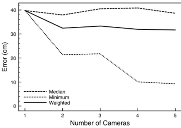
that it is very difficult to determine which of these is the best, it is preferable to somehow exploit all of these esti-mates rather than simply selecting the first or a random estimate. Figure 7 illustrates the effect that adding more cameras has on the error in the area that is in common view of all of the cameras. Note that the x-axis indicates how many cameras are actually viewing a particular com-mon area; there is always a leader node that provides the world mapping but, for the purpose of this experiment, is not viewing the same area and is not included in the camera count. This is done to avoid deflating the error to a gen-erally unrealistic degree, since the leader can map perfectly from its image to the world. The 3 curves are explained as follows:
Median: Each camera independently localizes a set of points from an area common to all cameras. For each point in this area, the median error across all cameras is used as the error for that point. The median error across the entire common area is plotted in the figure. This curve demon-strates the expected performance of the localization when the cameras localize without knowledge of other camera’s estimates for the same point, and a random point is selected as the true localization.
Minimum: Again, each camera independently localizes a set of points from an area common to all cameras. For each point in this area, the minimum error across all cameras is used as the error for that point. The median error across the entire common area is plotted in the figure. This line demonstrates the best possible performance of the localiza-tion using these cameras in this area, as if there is an oracle that can tell which camera produces the best estimate for a given point.
Weighted: Each camera independently localizes a set of points from an area common to all cameras. Each camera’s estimate is weighted by the inverse of the total mean squared error of the path it travels to the leader, and summed to form one localization estimate across all cameras for each point.
1 2 3 4 5 6 Number of Cameras 0.5 0.6 0.7 0.8 0.9 Coverage (% area)
Figure 6: Effective coverage, the percentage of total area that is visible in at least one camera, increases with the number of cameras.
This scheme demonstrates a possible method for combining localization estimates when multiple cameras simultaneously see a fall, which is likely in a dense camera network.
Figure 7 demonstrates that in the best case, adding more cameras has the potential to significantly decrease the local-ization error in the area visible to all cameras. However, in practice it can be difficult to select the camera that provides the best estimate for a given location. The weighted mean technique we present demonstrates one relatively effective technique for combining estimates from several cameras to improve the localization error over randomly choosing one of the estimates.
6.
RELATED WORK
In this section, we cover related work in the wireless sen-sor network, as well as vision communities on the design of efficient camera sensor networks.
Camera sensors: There exist several types of camera sensor nodes, each with different resources and capabilities. The Cyclops [14] and CMUCam [16] are examples of low-power nodes capturing low-resolution images with limited computation capabilities. XYZ [11] is a power-aware sen-sor platform which can be equipped with image sensen-sors. Panoptes [4] is a camera sensor node comprising of a webcam capturing high-resolution images and a Intel StrongARM PDA processor for reasonably high computation resources. In this work, we have developed techniques for low-power resource constrained camera nodes, and our solutions can be applied to more powerful nodes as well.
Camera-based Localization:There has been consider-able work on multi-hop localization in wireless sensor net-works. Less work has focused on multi-hop localization us-ing low-power cameras. In particular, the idea of minimizus-ing error in multi-hop localization (e.g.: [17]) and information-driven routing (e.g. [22]), have been proposed. The novelty of our work lies in understanding the problem of joint er-ror minimization and routing for camera-based localization, which to our knowledge has not been addressed before.
1 2 3 4 5 Number of Cameras 0 10 20 30 40 Error (cm) Median Minimum Weighted
Figure 7: Localization error in an area commonly visible to multiple cameras. Note that the x-axis indicates how many cameras are actually viewing a particular common area; there is always a leader node that provides the world mapping but, for the purpose of this experiment, is not viewing the same area. See the text for a full description.
positioning and calibrating camera-based sensor nodes. For example, [7] and [9] study the problem of localizing and cal-ibrating the camera sensors using reference beacons such as LED emissions. In contrast, we are concerned with localiz-ing persons movlocaliz-ing in the camera field of view. Another in-teresting problem that has been considered is explicit place-ment of cameras for coverage. [20] solves the problem of efficient placement of cameras given an area to be covered to meet task–specific constraints. While this relates to our work, we are more concerned with ad-hoc and unplanned deployments of cameras.
Fall Detection: A variety of approaches and systems have been developed for fall detection and alerts, including wearable commercial devices [10][19]. [12] uses an overhead camera to learn the locations in a room where a person com-monly remains still for short lengths of time, and assumes a fall has occurred if someone is still in an unusual area. Audio cues are combined with video in a Hidden Markov Model-based approach proposed by [18], which can reduce the false alarm rate when compared to a video-only approach. These approaches are effective, however they utilize full-sized cam-eras and computationally expensive machine learning algo-rithms running on PCs. Another interesting approach to fall detection is proposed in [8]. In that work, the subject wears a small accelerometer which is able to detect falls but is prone to false alarms if a person sits down with too much force. To reduce these errors, smart cameras also monitor the scene and determine a person’s posture by detecting the location of their head relative to the body. The general ap-proach to fall detection in this work is similar to ours, but they also use more powerful hardware and the extra wear-able devices, which we try to avoid.
1 2
3 4
5 6
Figure 8: Sample images from the six cameras. Note that the checkered carpet does not aid the system in any way.
7.
CONCLUSIONS
The system presented here demonstrates that even very low-power, low-resolution cameras and motes can be used to detect and localize falls with a localization error of less than 50cm. Furthermore, the system only requires the manual calibration of one camera per group of overlapping cameras. We argue that this type of setup, with a small energy and physical footprint, is preferable for use in home settings over traditional sized cameras and PCs. The sample implementa-tion provides a design that can be used with slightly higher end hardware and more robust algorithms in order to further improve performance. Our results using simple, low-power cameras running on Crossbow MICAz platform demonstrate that we can achieve reliable fall detection, and localization accuracy beween 40-60 cms in a 3-hop network of cameras. We must be very sensitive to the privacy concerns that will undoubtedly arise with the thought of placing cameras in someone’s home. It is essential that anyone who is using this or a similar system is fully aware of the details of its operation: specifically that cameras will be processing
im-Figure 9: A sample of the images used to evaluate fall detection. The left column contains normal sce-narios, and the right contains fall scenarios. The bottom left image causes a false positive on the Cy-clops.
ages of them in potentially vulnerable situations. Feedback on this and related applications has been sought from el-derly focus groups and is currently being evaluated by our research colleagues in the Smith College School for Social Work.
In our future work, we will explore the possibility of intel-ligently merging location estimates for points seen by mul-tiple cameras in order to reduce the total mapping error. A more robust point correspondence gathering scheme that does not rely on the movement of people could also improve the overall quality of the mappings. Finally, we may look at methods of reducing the number of samples that each cam-era takes by intelligently sampling only active areas of the environment.
8.
ACKNOWLEDGEMENTS
This work was supported in part by NSF grants SES-0527648, CNS-0626873, CNS-0546177, and CNS-0520729.
9.
REFERENCES
[1] Numerical Recipes in C: The Art of Scientific Computing. Cambridge University Press, 1992.
[2] A. Agarwal, C. V. Jawahar, and P. J. Narayanan. A survey of planar homography estimation techniques. Technical report, IIT-Hyderabad, 2005.
[3] Crossbow Wireless Sensor Platforms.
http://www.xbow.com/products/wproductsoverview.aspx. [4] W. Feng, B. Code, E. Kaiser, W. Feng, and M. L. Baillif.
Panoptes: Scalable low-power video sensor networking technologies. InACM Transactions on Multimedia Computing, Communications and Applications, January 2005.
[5] R. Hartley. In defense of the 8-point algorithm. InIEEE Transactions on Pattern Analysis and Machine Intelligence, volume 19, pages 580–593, 1997.
[6] R. Hartley and A. Zisserman.Multiple View Geometry in Computer Vision. Cambridge University Press, 2000. [7] D. Jung, T. Teixeira, A. Barton-Sweeney, and A. Savvides.
Model-based design exploration of wireless sensor node lifetimes. InProceedings of the Fourth European
Conference on Wireless Sensor Networks (EWSN), 2007. [8] A. Keshavarz, A. Maleki-Tabar, and H. Aghajan.
Distributed vision-based reasoning for smart home care. In
ACM SenSys Workshop on Distributed Smart Cameras, 2006.
[9] P. Kulkarni, P. Shenoy, and D. Ganesan. Approximate initialization of camera sensor networks. InProceedings of the Fourth European Conference on Wireless Sensor Networks (EWSN), 2007.
[10] LifeAlert. http://www.lifealert.com. [11] D. Lymberopoulos and A. Savvides. Xyz: A
motion-enabled, power aware sensor node platform for distributed sensor network applications. InProceedings of Information Processing in Sensor Networks (IPSN), SPOTS track, April 2005.
[12] H. Nait-Charif and S. J. McKenna. Activity summarisation and fall detection in a supportive home environment. In
International Conference on Pattern Recognition, 2004. [13] L. R. Rabiner. A tutorial on Hidden Markov Models and
selected applications in speech recognition.Proceedings of the IEEE, 77(2):257–286, 1989.
[14] M. Rahimi, R. Baer, J. Warrior, D. Estrin, and M. Srivastava. Cyclops: In situ image sensing and
interpretation in wireless sensor networks. InProceedings of ACM SenSys, 2005.
[15] P. Roessler, S. Consolvo, and B. Shelton. Phase 2 of Computer-Supported Coordinated Care project. Technical Report IRS-TR-04-006, Intel Research Seattle, 2004. [16] A. Rowe, C. Rosenberg, and I. Nourbakhsh. A Low Cost
Embedded Color Vision System. InInternational Conference on Intelligent Robots and Systems, 2002. [17] A. Savvides, L. Girod, M. Srivastava, and D. Estrin.
Localization in Sensor Networks, Chapter in Wireless Sensor Networks. Kluwer, 1991.
[18] B. U. Toreyin, Y. Dedeoglu, and A. E. Cetin. Hmm based falling person detection using both audio and video. In
IEEE Workshop on Human-Computer Interaction, 2005. [19] Tunstall Fall Detector.
http://www.tunstallaustralasia.com/fall detector.php. [20] U.M. Erdem and S. Sclaroff. Optimal Placement of
Cameras in Floorplans to Satisfy Task Requirements and Cost Constraints. InOMNIVIS Workshop, 2004. [21] A. Williams, D. Xie, S. Ou, R. Grupen, A. Hanson, and
E. Riseman. Distributed smart cameras for aging in place. InACM SenSys Workshop on Distributed Smart Cameras, 2006.
[22] F. Zhao, J. Liu, J. Liu, L. Guibas, and J. Reich. Collaborative signal and information processing: An information directed approach.Proceedings of the IEEE, 91(8):1199–1209, 2003.