Property-Driven Development
∗† (Extended Abstract)Hubert Baumeister, Alexander Knapp, and Martin Wirsing
Institut f¨ur Informatik
Ludwig-Maximilians-Universit¨at M¨unchen, Germany
{baumeist
,
knapp
,
wirsing}@pst.ifi.lmu.de
Abstract
Early test development and specification enhance the quality and robustness of software as experience with agile software development methods shows. The methods propa-gate test-first techniques and early prototyping through ex-ecutable design models. We propose to enhance test-driven development to a more general property-driven develop-ment technique: Property-driven developdevelop-ment ties together automatic tests, formal specification, and executable UML models by developing these three views together instead of one after the other as is common practice. Scenarios and properties serve as a combined basis for system specifi-cation and test cases. By extracting common properties of several scenarios we obtain invariants and pre- and post-conditions. The behavior of the system is described UML state machines. For testing we insert invariants and pre-and postconditions as assertions in the code generated from the state machines. For verification, we use model checking. For this we have to restrict the models to finite domains. Therefore we construct suitable abstractions of the scenar-ios and the system behavior and verify the abstractions us-ing a model checker.
1. Introduction
The two main questions when developing software are: “Are we developing the right software” and “Are we de-veloping the software right”. The first question is about the software meeting the explicit and implicit requirements of the customer and the second question is about the quality
∗ This research has been partially supported by the InOpSys project (WI 841/6-1) sponsored by Deutsche Forschungsgemeinschaft (DFG) and by the EC 5th Framework project AGILE: Architectures for Mobility (IST-2001-32747).
† appeared in Proc. SEFM 2004, 2nd Int. Conf. on Software Engineer-ing and Formal Methods, BeijEngineer-ing. IEEE.
and reliability of the software. Does the software indeed perform the way it is intended?
The first problem concerns user requirements elicitation. In most cases the detailed user requirements are not known up front. Instead, they evolve with the feedback from the de-velopment process. There are several approaches to provide feedback: One way is to present the customer with several diagrammatic views on the software for inspection and dis-cussion [5]. UML, for example, provides diagrams like use-case diagrams, activity diagrams, and class diagrams for this purpose. Another means are executable models and proto-types which allow one to simulate the behavior of the soft-ware. Finally, an excellent means for getting feedback is the running program. This is also the most expensive way to provide feedback.
Building the model right implies that one has to know what the right system is. This requires an independent view on the software which states the properties the software should have and against which the software can be checked. These properties are the formalization of the functional and non-functional requirements of the proposed system. As we have seen above, these requirements are likely to be un-known in all detail before starting the implementation of the software. Thus, we propose to develop the specification of the software together with the software.
This idea is also present in extreme programming [2]. Extreme programming is an agile software development process that emphasizes small iterations with the customer being able to play with the software almost from the begin-ning. In addition, tests are written before the actual code is written, called test-driven development [3]. This provides a second, more declarative view on the software, enhances the quality of the code, and provides the safety net that al-lows one to react to changes in requirements resulting from the feedback with the software.
However, extreme programming has two drawbacks. First, tests can only express particular scenarios but not more general properties of the software to be built. Sec-ond, with extreme programming already the program code
construct Model test Use Case Property extract & generalize Abstracted
Model verify (model check)
Test Scenario detail Instrumented Model implements test with assertions
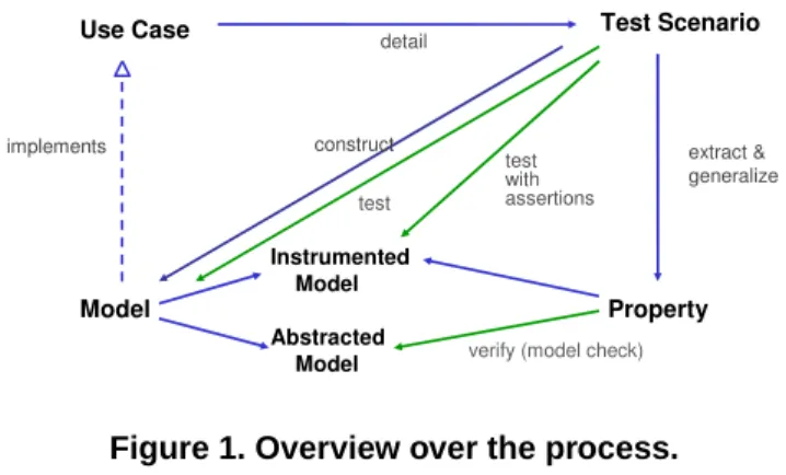
Figure 1. Overview over the process.
is built. Thus, the power of using more abstract model-ing techniques is lost and the programmer is forced to deal with implementation details.
We propose a property-driven approach where an exe-cutable model of the software is developed together with its specification and tests. We work on the design level and use abstract executable models instead of directly writing code. Then the resulting code is either obtained manually by re-fining the model, by generating code from the model, or by transforming the model into other models which are more suitable for code generation, e. g. using techniques from model-driven architecture [13].
In Sect. 2 we introduce the property-driven software de-velopment process. Section 3 applies an iteration of the pro-cess to the MUD game case study developed in the EU-project AGILE1. Finally, Sect. 4 contains some concluding remarks.
2. The Process
Property-driven development is an iterative pro-cess guided by user stories and use cases (cf. Fig. 1). The steps of the process are the following:
1. Select a use case from the current user story.
2. Define a scenario, either an intended scenario or a sce-nario which is not permitted, as a UML interaction di-agram.
3. Generate tests from the interaction diagram.
4. Extend the current model to cope with the new sce-nario until all tests succeed.
5. Identify system properties by generalizing the sce-nario.
6. Depending on the type of properties, either instrument the model with assertions generated from the
proper-1 Architectures for Mobility;www.pst.ifi.lmu.de/projekte/ agile.
ties and run the tests again, or use model checking techniques to verify or validate the property.
Step 1 As with extreme programming we capture the
func-tional and non-funcfunc-tional requirements by so-called user stories. Each user story describes an aspect of the behav-ior of the software system relevant to the customer. Starting from a user story—selected according to the priority given to the user story by the customer—the first step is to identify the use cases involved in that user story. While a user story describes a particular use scenario of the system, a use case describes a functionality of the system. Thus a user story may involve several functionalities from a system, while, in general, several user stories are needed to describe the com-plete functionality of one use case.
Step 2 After having identified the use cases, a use case is
selected and the scenarios of that use case relevant for the current user story are identified. We have two kinds of sce-narios, scenarios that describe the intended behavior of the system and scenarios that are not allowed to occur. We use the interaction diagrams of UML 2.0 [12] to model such behaviors as they allow us to model both types of scenar-ios which is not possible with previous versions of UML.
Step 3 Next we select one of these scenarios and generate
JUnit [4] or Fit [7] tests for them from their interaction dia-gram. JUnit is a unit testing framework developed by Kent Beck and Erich Gamma for Java, and Fit is a similar frame-work as JUnit but uses HTML tables instead of Java classes for defining the tests and is mainly used for acceptance test-ing. We are now able to run the tests against the current model of the system. Of course these tests will fail as the current model is not yet extended to cope with the defined scenario. This will be done in the next step.
Step 4 In this step, the current model is extended to cope
with the scenarios defined in the previous step. We use UML class diagrams to describe the structure of the model and UML state machines to describe their behavior. The HUGO2
tool allows us to generate executable Java code from the state machines. HUGOis a UML model translator that sup-ports UML static structure, UML state machines, and UML interactions. For translating a UML model with HUGO, the UML model has to consist of a set of active classes with their accompanying state machines. Such a UML model can either be given as an XMI 1.0/1.1-file or in a simple textual format called UTE.
Step 5 Running the tests successfully is a pretty good
dication that the state machine indeed implements the in-tended behavior, i. e., that we developed the software right. However, tests are only able to express particular scenarios
0 6 2 1 5 4 3
Start Room Special Room
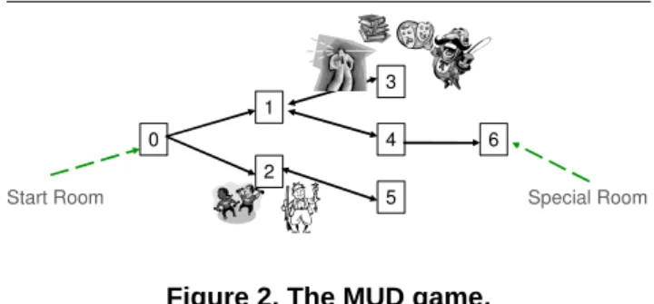
Figure 2. The MUD game.
and not general classes of scenarios. In this step the prop-erties of the system are identified by generalizing from the scenarios. Currently we can handle two types of properties: OCL formulas [15] for class invariants and pre- and post-conditions for methods, and safety and liveness properties expressed in an extension of OCL by path quantifiers and temporal operators as used in CTL.
Step 6 To validate the OCL constraints, we would like to
instrument the state machines with the OCL constraints by adding the invariants, pre- and postconditions before and after each method call. Since this is not yet supported by our tools we proceed actually as follows. We use HUGO
to translate the state machines into Java code. In a second step we translate the OCL constraints to the Java Model-ing Language (JML) [11] and use the assertion generator for JML to instrument the generated code [6]. When run-ning the tests, these assertions will be executed as well. Thus in this step we check the validity of the OCL prop-erties from which assertions were generated. For tempo-ral properties we use HUGO to translate the UML model and the constraints into specifications for the model check-ers SPIN[8] and UPPAAL[10] and for the interactive the-orem prover KIV[14]. The actual verification is performed by these off-the-shelf tools.
The next iteration starts by looking at the current use case. Are all interesting scenarios defined and dealt with? If this is not the case, the next iteration starts with the next scenario. After finally all interesting scenarios for a use case have been dealt with, we can move on to the next relevant use case in the current user story. Similarly, after all the sce-narios and use cases relevant for a user story have been fin-ished, one moves on to the next user story.
3. The MUD Game
To illustrate the property-driven development process, we use a multi-user dungeon game (MUD) played via mo-bile phones. At the beginning of the game, the player is in the start room of a maze of connected rooms. His task is to find the special room from which he can advance to the start room of the next level or finish the game, if there is no
One Player Game
Game with Distribution
Functionality Level
Of
Abstraction Multi Player ... Game Multi Player(Fighting)Game
Game with Computer Controllerd Players
Figure 3. User stories for the MUD game.
next level (cf. Fig. 2). While moving through the rooms, the player can interact with other players by talking to them, trading objects with them, and fighting. These players can be human or computer controlled.
3.1. User Stories, Uses Cases, and Tests
The MUD game is divided into the following user stories (cf. Fig. 3):
1. One player game. Only one player is present in the game and he can move through the rooms of the game. 2. Multi-player game. Now the game contains several hu-man players that move through the game and that in-teract by talking and trading objects.
3. Multi-player game (fighting). In this user story the players can also interact by fighting each other. 4. Game with computer-controlled players. In this user
story, computer controlled players are added to the game.
5. Adding distribution. In the previous user stories distri-bution did not play a role. In this user story we move to a more concrete level by adding distribution aspects to our model.
While user stories 1 to 4 represent functional requirements, user story 5 adds a requirement on the architecture of the system. The order in which the user stories are defined re-sults in first producing a model for the functional require-ments of the game and then adding implementation details, like distribution, to the model.
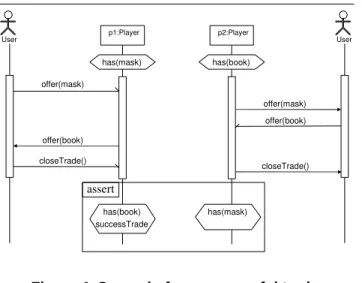
In the following, we assume that the first user story has already been finished and that we are working on the multi-player game user story. The use cases identified for this user story are shown in Fig. 5 and we select the use case trade objects to work on. The first scenario of that use case, shown in Fig. 4, is the successful trade scenario. We start with as-serting that the first player has a book and the second player has a mask. Then the first user initiates the trade by send-ing his player object the request to offer the second user the book. For example, he can do this by selecting on his mobile phone the book in his inventory and then selecting the option for trading. The second user receives from his
offer(book) closeTrade() p1:Player p2:Player has(mask) has(book) has(book) successTrade has(mask) assert offer(mask) User User offer(mask) offer(book) closeTrade()
Figure 4. Scenario for a successful trade.
player object the request for a trade, for example, by pre-senting a dialog on the display of the second player. The second user accepts the trade by offering the mask. Finally, the first player accepts the counter offer by closing the trade which again is displayed on the second user’s screen. We as-sert that the first player has the mask and the second player has the book. In addition, the first player has set his attribute
successTradeto true to indicate that a successful trade
has taken place.
Note that no interaction is shown between the player ob-ject of the first player and the second player obob-ject. We are only interested in the interaction between the users and their player objects but not in the interaction between the player objects because we are defining the behavior of the MUD game relevant to the customer and not its implementation.
MUD User Look around Move around Trade objects . . .
Figure 5. Use cases for the multi-player game user story.
fit.ActionFixture
start Trading
check has book p1 true
check has mask p2 true
action offer book p1
action offer mask p2
action close trade p1
check has mask p1 true
check success trade p1 true
check has book p2 true
Figure 6. Fit table representing the success-ful trade scenario.
To generate tests from the interaction, we translate the above scenario to the following Fit table (cf. Fig. 6). The head of the table, fit.ActionFixture, is the name of a class defining how the following rows are to be in-terpreted.Start,action, andcheckare Fit keywords defined by fit.ActionFixture; the interpretation of
offer,close trade,has, andsuccessTradehave
to be provided by the modeler in so-called fixture classes, in this case classTrading. Finally,book,mask, andtrue
are parameters to the operations.
3.2. The Model
The next step of property-driven development is to ex-tend the model from the previous iteration in such a way that the tests generated from the scenario in this iteration succeed. The extended class diagram is shown in Fig. 7. ClassesPersonalObject, andOfferare added to the class diagram of the previous iteration and classPlayer
is extended by the attributesuccessTradeand methods
has,offer, andcloseTrade. The class diagram shown
in Fig. 7 uses the stereotypes for mobile objects and loca-tions from Baumeister et al. [1].
The behavior of the player class if given by the state ma-chine in Fig. 8. The state mama-chine defines the behavior of the players that is sufficient to satisfy the tests for the suc-cessful trade scenario but nothing more. We test that the state machine implements the successful trade scenario by running the generated Fit tests from Fig. 6 against Java code generated by HUGOfrom the state machine.
3.3. Verification and Validation
By looking at the successful trade scenario we see that it tests that book and mask are exchanged, but what about other objects like sword and shield? To express that we do not care about what objects are being exchanged, as long
<<mobile location>> Player post:… successTrade = true self.has(lastOffer.object) …
offer(PersObj o,Player to) closeTrade() has(PersObj o) : bool successTrade : bool 0..* 0..1 <<mobile object>> PersonalObject has Offer lastOffer object 1 0..1 0..1 1 0..1 1 <<location>> Room 1 0..* move(Room)
Figure 7. Class diagram for the successful trade scenario.
as they are being exchanged, we cannot use tests alone; in-stead we have to use more expressive formulas like the post-condition oncloseTradein Fig. 7.
By instrumenting the code generated from the state ma-chine with assertions generated from the constraints, we are able to check with each executed test that the pre- and post-conditions are not violated. Note that this approach can be only used as a first validation of the specification w. r. t. the model. In particular, since the tests only check the exchange of book and mask, the assertions are only tested for the ex-change of book and mask. However, in comparison to the corresponding test, which is only executed once, the asser-tions are checked also with the execution of the other tests.
waiting receivedOffer offer(o,to)/ lo.p._recOffer(o,this) closeTrade()/ lo.p._closeTrade() successTrade=true has->including(lo.object) lo.p._del(lo.object) offer(o,from)/ lo.p._recOffer(o,from) _closeTrade()/ u.closeTrade() has->incl.(lastOffer.object) p._del(lastOffer.object) lo.p is short for lastOffer.player
_recOffer(o,from)/ u.offer(o,from)
Figure 8. Player state machine.
waiting receivedOffer offer(o,to)/ lo.p._recOffer(o,this) closeTrade()/ lo.p._closeTrade() successTrade=true has->including(lo.object) lo.p._del(lo.object) offer(o,from)/ lo.p._recOffer(o,from) _closeTrade()/ u.closeTrade() has->incl.(lastOffer.object) p._del(lastOffer.object) lo.p is short for lastOffer.player
_recOffer(o,from)/ u.offer(o,from)
Figure 9. Abstracted player state machine.
In later stages of the development where we have additional scenarios and thus additional tests for trading, the assertion generated from the postcondition forcloseTradeis al-ways checked whenever during these tests acloseTrade
is performed.
In addition to OCL constraints we can use temporal logic formulas to express desired safety and liveness properties of the system. For example we express that the trading proto-col we have defined so far does not deadlock and that both players agree on the successful outcome of the trade, i. e., that after performingcloseTrade, thesuccessTrade
attribute of both players is true.
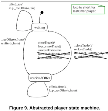
To use a model checker to check these properties, we have to restrict our model to finite domains by removing all operations with infinite domains from the state machine (cf. Fig. 9). The property of deadlock freedom can be ex-pressed by the temporal OCL constraint:
AG not deadlock
And the property that both player objectsp1andp2agree on the outcome of a trade is:
AG (u1.inState(Idle) and u2.inState(Idle)) implies
p1.successTrade == p2.successTrade
HUGO translates the resulting UML model into UPPAAL
timed automata: Each state machine is translated into a timed automaton for representing its behavior proper as well as a timed automaton for its event queue. The timed au-tomata communicate over a shared network that temporar-ily stores the messages that are exchanged between the state machines and guarantees that each message is delivered to
offer(book) closeTrade() p1:Player p2:Player has(mask) has(book) has(book) successTrade assert offer(mask) User User offer(mask) offer(book) has(mask) successTrade closeTrade()
Figure 10. Corrected scenario for a success-ful trade.
its intended receiver within a predetermined time bound.
Thedeadlockproperty is translated into the timed CTL
logic of UPPAAL, expressing that a deadlock of the over-all system can only arise, if either some event queue or the network has overflown.
Deadlock freedom is easily proved; however, the prop-erty that both players agree on the outcome of the trade does not hold. This reveals a bug in the original state ma-chine in Fig. 8 and in our test scenarios. In the original sce-nario (cf. Fig. 4), we have only tested for the first player that he thinks that the trade was successful but not for the second player. Thus, we have not only to correct the state machine by settingsuccessTradeto true in the transi-tion from statereceivedOfferto statewaiting trig-gered by event_closeTradein Fig. 8, but also to correct the test scenario to check forsuccessTradein the asser-tion of the second player (cf. Fig. 10).
In addition to generating tests to check the validity of scenarios, we can use HUGOto directly verify that the suc-cessful trade scenario in Fig. 10 is a possible scenario of the corrected state machine. In UTE, this interaction is ren-dered as follows: interaction successfulTrade { u1 -> p1 : offer(); p2 -> u2 : offer(); u2 -> p2 : offer(); p1 -> u1 : offer(); u1 -> p1 : closeTrade(); p2 -> u2 : closeTrade();
assert p1.successTrade == 1 and p2.successTrade == 1; }
whereu1andu2are the user objects, andp1andp2the corresponding player objects. HUGOtranslates such an
in-Scenarios / Tests Model Properties Use Case 1 Use Case 2 Use Case 1 … … … Use Story 1 Use Story 2 … …
Figure 11. The iterative nature of property-driven development.
teraction into an observer automaton [9] that runs concur-rently with all objects of the model and registers all mes-sages that are exchanged between the objects. The observer automaton validates that the exchanged messages adhere to the order specified in the interaction. However, the observer automaton allows for an arbitrary number of messages be-tween two specified messages and thus can ignore inter-nal message exchanges. For the resulting overall system of timed automata, HUGO produces the requirement that the final state of the observer automaton can be reached, i. e., that a run according to the interaction is indeed possible. Furthermore, if the interaction specification ends with an
assertstatement, a requirement is generated that
when-ever the final state of the observer automaton is reached the asserted property must hold. For the successful trade exam-ple we get the following UPPAALformulas:
E<> observer.ObserverSuccess A[] observer.ObserverSuccess imply
(objP1SM.successTrade == 1 and objP2SM.successTrade == 1)
whereobjP1SMandobjP2SM are the HUGO-generated names forp1andp2.
3.4. Next Iteration
We have up to now only dealt with the successful trade scenario. A next scenario could consider the situation where the trade is canceled by the second user. This yields another extension of the class diagrams and the state machine. Fur-thermore, additional constraints are defined, e. g., that af-ter the trade was canceled, the objects proposed for trading remain with their original owner andsuccessTradeis false. The properties of deadlock freedom of the trade pro-tocol and that the users agree on the outcome of the trade (successful or canceled) do not change and have to be ver-ified again using the extended state machine of this itera-tion.
4. Concluding Remarks
With property-driven development the specifica-tion, tests, and executable model are developed together (cf. Fig. 11) which is important to get immediate feed-back from the customer. This ensures that the system we are building is the right system, that is, that the sys-tem satisfies the needs of the customer. The specifica-tion together with the tests increase our confidence that we have built the system right, that is, that the software in-deed performs as required by the customer. In addition to raising our confidence in the software, the specifica-tion can be used as a documentaspecifica-tion for the system.
Property-driven development proceeds in small itera-tions. Thus the changes to the specification, tests, and model w. r. t. the previous iteration are only small. This makes it easier to keep the three views synchronized. Keeping the views synchronized allows to feed back knowledge gained building one view into the other views. For example, one may be able to simplify the model because making the prop-erties the model should satisfy explicit reveals unnecessary complexity in the model. Or, trying to find a model for the desired properties, one may discover that the properties are not complete, e. g., that some cases are missing or that the specification is not implementable.
Specification and tests provide a safety net for easy refac-toring of the model, so that it becomes easy to incorporate the feedback from the customer, which is needed to imple-ment the right system.
Currently we are integrating these techniques into a user-oriented collaborative development environment.
References
[1] H. Baumeister, N. Koch, P. Kosiuczenko, and M. Wirs-ing. Extending activity diagrams to model mobile systems. In M. Aksit, M. Mezini, and R. Unland, editors, Objects, Components, Architectures, Services, and Applications for a Networked World. International Conference NetObjectDays, NODe 2002, Erfurt, Germany, Oct. 7–10, 2002. Revised Pa-pers, volume 2591 of LNCS, pages 278–293. Springer, 2003. [2] K. Beck. Extreme Programming Explained: Embrace
Change. Addison-Wesley, 1999.
[3] K. Beck. Test Driven Development: By Example. Addison-Wesley, 2002.
[4] K. Beck and E. Gamma. JUnit cookbook. www.junit. org, 2002.
[5] G. Booch, J. Rumbaugh, and I. Jacobson. The Unified Mod-eling Language User Guide. Object Technology Series. Ad-dison Wesley, 1999.
[6] Y. Cheon and G. T. Leavens. A runtime assertion checker for the Java Modeling Language (JML). In H. R. Arabnia and Y. Mun, editors, Int. Conf. Software Engineering Research and Practice (SERP’02), pages 322–328. CSREA Press, Las Vegas, 2002.
[7] W. Cunningham. FitWiki.fit.c2.com, 2004.
[8] G. J. Holzmann and G. J. Holzmann. The Spin Model Checker: Primer and Reference. Addison Wesley, 2003. [9] A. Knapp, S. Merz, and C. Rauh. Model checking timed
UML state machines and collaborations. In W. Damm and E. R. Olderog, editors, Proc. 7th Int. Symp. For-mal Techniques in Real-Time and Fault Tolerant Systems (FTRTFT’02), volume 2469 of LNCS, pages 395–416. Springer, Berlin, 2002.
[10] K. G. Larsen and W. Yi. UPPAAL in a nutshell. Int. J. Softw. Tools for Techn. Transfer, 1(1–2):134–152, 1997.
[11] G. T. Leavens, A. L. Baker, and C. Ruby. JML: a notation for detailed design. In H. Kilov, B. Rumpe, and I. Simmonds, ed-itors, Behavioral Specifications for Businesses and Systems, chapter 12, pages 175–188. Kluwer, 1999.
[12] Object Management Group. Unified Modeling Language Specification, Version 2.0 (Superstructure). Adopted draft, OMG, 2003.www.uml.org.
[13] Object Management Group. Model driven architecture.
www.omg.org/mda, 2004.
[14] W. Reif. The KIV approach to software verification. In M. Broy and S. J¨ahnichen, editors, KORSO: Methods, Lan-guages, and Tools for the Construction of Correct Software, volume 1009 of LNCS. Springer, 1995.
[15] J. Warmer and A. Kleppe. The Object Constraint Language: Precise Modeling with UML. Addison-Wesley, 1st edition, 1998.