GAS INTERNAL COMBUSTION ENGINE WITH
INTERNAL MIXTURE FORMATION
Doc.Ing. Scholz Celestýn, Ph.D.
Technical University of Liberec, Department of vehicles and engines, Hálkova 6, 461 17
Liberec, tel: +420 48 5353155, fax: +420 48 5353139, email.: [email protected]
Ing. Brabec Pavel
Technical University of Liberec, Department of vehicles and engines, Hálkova 6, 461 17
Liberec, tel: +420 48 5353159, fax: +420 48 5353139, email.: pavel.brabec @tul.cz
Abstract
Fuel mixture formation inside the cylinder has become more prevalent in spark ignition
engines in recent years.
This concept can be beneficially utilized in gas internal combustion engines where direct
injection into an engine cylinder during compression is advantageous not only in increasing
volumetric efficiency but also in the elimination of undesired combustion process anomalies.
This work describes the gas fuel injection arrangements (natural gas or gas fuel mixture) into
a cylinder utilized in the laboratory of Technical University of Liberec, Department of
Vehicles and Engines. The paper deals with both a low-pressure injector design and a
high-pressure injector installation (100 bars) supplied by a specialized producer.
Keywords
gas internal combustion engine, direct injection, high-pressure injector, natural gas
Shrnutí
Tvoření palivové směsi uvnitř válce se v posledních letech používá stále častěji u zážehových motorů. Tento koncept lze s výhodou použít u plynových spalovacích motorů, kde přímá injektáž do válce motoru během komprese je výhodná nejen z hlediska zvýšení objemové účinnosti, ale i v zamezení nežádoucích anomálií spalovací-ho procesu. Příspěvek popisuje konstrukční uspořádání injektáže plynného paliva (zemního plynu, popř. směsi plynného paliva) do válce, která jsou realizována v laboratoři katedry vozidel a motorů Technické univerzity v Liberci. Jedná se jak o konstrukci nízkotlakého injektoru, tak i o zástavbu vysokotlakého injektoru (100 bar) do-daného specialisovaným výrobcem.
Klíčová slova
plynový zážehový spalovací motor, přímá injektáž, vysokotlaký injektor, zemní plyn
1. Introduction
Currently, there are about 5 million natural gas-operated passenger and commercial vehicles world-wide. In Europe, the highest numbers of natural-gas powered vehicles are operated in Italy, the Ukraine and Germany. According to manufacturer’s data the engine power of natural-gas operated passenger cars usually corresponds to 85 to 90% of their gasoline powered counterparts. Some manufacturers (e.g. Volvo and Mercedes) report the identical engine power for both natural gas and gasoline. Based on fuel utilization, the natural gas engines can be categorized as either single-fuel (natural gas only) or dual-fuel allowing for alternate operation on either natural gas or gasoline. The single-fuel engines are primarily used for buses, commercial vehicles and powered industrial trucks. The dual-fuel engines find their principal applications in passenger cars: in certain cases the gasoline operation serves for emergencies only.
2.
Mixture Formation Methods
The air and fuel mixture formation (preparation) represents an important part of the engine working cycle which impacts the mixture behavior with controlled ignition and the resulting combustion process. In principle, there are two concepts of the mixture preparation: internal and external.
The external mixture formation represents the simplest concept. An automobile gas operated engine can be equipped with a fuel system incorporating a gas and air mixer in the engine intake manifold or with gas injection into the engine intake by means of solenoids sequentially controlled for each cylinder. The mixer in the engine induction causes a pressure loss, and is, as a result, less suitable compared to injectors.
The internal mixture formation with the gas fuel injection directly into a working cylinder space is a more complex concept to develop and construct. The separation of fuel from air during the cylinder charge exchange eliminates back fires in the induction system, the achievable heat value increases and, consequently, the engine power grows. Depending on the injector inlet pressure two implementations of the concept can be distinguished: one using low-pressure injection and the other involving high-pressure injection.
Low-pressure injection with gas pressure below 2 MPa requires a longer duration and at high load the injection commencement must occur during the induction stroke, i.e. at the time when the inlet valve is open.
High-pressure injection with gas pressure between 10 and 12 MPa currently represents the most up-to-date and efficient concept of an internal mixture formation eliminating adverse combustion anomalies and benefiting from a stratified mixture formation in combination with lean mixture. In order not to restrict vehicle range high storage pressure has to be implemented. The fuel rails (storage containers/storage cylinders) accommodating 70 MPa pressures are developed by Dynetek Europe [1].
Figure 1: An example of a gas fuel system arrangement with external sequential natural gas injection [4]
3.
High Pressure Injection
To verify the advantages of and benefits from the high pressure injection of gas directly into an engine cylinder, a new testing bench is presently being prepared in the Piston internal combustion engine laboratory (Technical University of Liberec, Department of Vehicles and Engines). With this project, our laboratory extends the research programs to the area of the internal mixture formation for small engines designed for passenger cars; namely a three-cylinder internal combustion engine having a total displacement of 1.2 dm3.
The engine concept is based on new high-pressure injectors with 10 MPa inlet pressure. At the moment, our laboratory uses injectors produced by Hoerbiger Valve Tec (the injectors have been developed within the Europen program HylCE).
After being installed in a three-cylinder, 1.2 dm3 engine, with the gas inlet pressure of 10 MPa and
the cross-sectional area of flow of 1 mm2, these high-pressure injectors (see Fig.3) shorten the
injection duration to a maximum 50° of the crank angle. Consequently, even at maximum power, the injection can be timed in the compression stroke only after the intake valve closes. The electronic system for the controlling and monitoring of engine operation has been supplied by ADCIS Company. The high-pressure injector nozzles are shown in Fig.4.
Figure2: Test bench with gas engine (total displacement of 1.2 dm3
Figure 4: High-pressure injector supplied by Hoerbiger Valve Tec [2]
Obrázek 4: Tryska vysokotlakého injektoru od firmy Hoerbiger Valve Tec [2]
Injector Tip Geometry
• 6 holes total • no central hole
• equal 60deg orientation
• 90 deg cone incl. angle (each hole 45 deg from injector axis) • holes sized to meet existing flow
specifications
90 deg
Figure 3: High-pressure injector supplied by Hoerbiger Valve Tec [2]
4.
Injection Parameter Computation
The following injection parameter computations concentrate on the establishment of the gaseous fuel mass flow rate and valve exposure time.
Universal gas constant
=
8314
⋅
−1⋅
−1K
kmol
J
R
Molar mass Mfuel =16kg⋅kmol−1 Specific gas constant = =519,625 ⋅ −1⋅ −1
K kg J M R r fuel Poisson’s ratio
κ
=
1
,
4
Effective min. cross section
A
=
1
mm
2=
1
⋅
10
−6m
2Inlet temperature (°C)
T
0=
37
°
C
=
310
K
Inlet pressure (bar)
p
0=
100
bar
=
1
⋅
10
7Pa
Outlet pressure (bar)
p
2=
3
bar
=
3
⋅
10
5Pa
Critical pressure ratio
0
,
528
1
2
1 0=
⎟
⎠
⎞
⎜
⎝
⎛
+
=
κ+ κκ
p
p
krActual pressure ratio 0,03
0
2 =
p p
Flow in a minimal cross section will be critical if
0 0 2 p p p p kr < , otherwise it is subcritical.
Flow coefficient critical
0
,
484
1
2
2
1 1=
⎟
⎠
⎞
⎜
⎝
⎛
+
⋅
=
− + κ κκ
κ
ψ
subcritical⎥
⎥
⎥
⎦
⎤
⎢
⎢
⎢
⎣
⎡
⎟⎟
⎠
⎞
⎜⎜
⎝
⎛
−
⎟⎟
⎠
⎞
⎜⎜
⎝
⎛
⋅
−
=
+ κ κ κκ
κ
ψ
1 0 2 2 0 21
p
p
p
p
Mass flow of gas
1 1 1 0 0 0,01705 17,05 61,38 2 = ⋅ − = ⋅ − = ⋅ − ⋅ ⋅ ⋅ ⋅ = kg s g s kg h r T p A mfuel
ψ
Maximum injected quantity Injection angleCA
open=
50
°
Engine speed=
4500
min
−1n
Injection durationms
n
CA
t
open open1
,
85
1
360
⋅
=
=
Injected fuel quantity
mg
n
CA
m
m
inj fuel open1
31
,
57
360
⋅
⋅
=
The selection of the injector necessitated a study of the engine head design modifications required for its installation. The work was far from easy due to the considerable dimensions of the selected injectors (in proportion to the 1.2 dm3 engine head size). In conducting these modifications we strove
to comply with the following conditions: • simple but reliable design
• conveniently chosen direction of gaseous fuel injection
• minimal impact on engine head cooling (water port constriction) • no interference with the space for lubricating oil
• no reduction in the suction port cross section
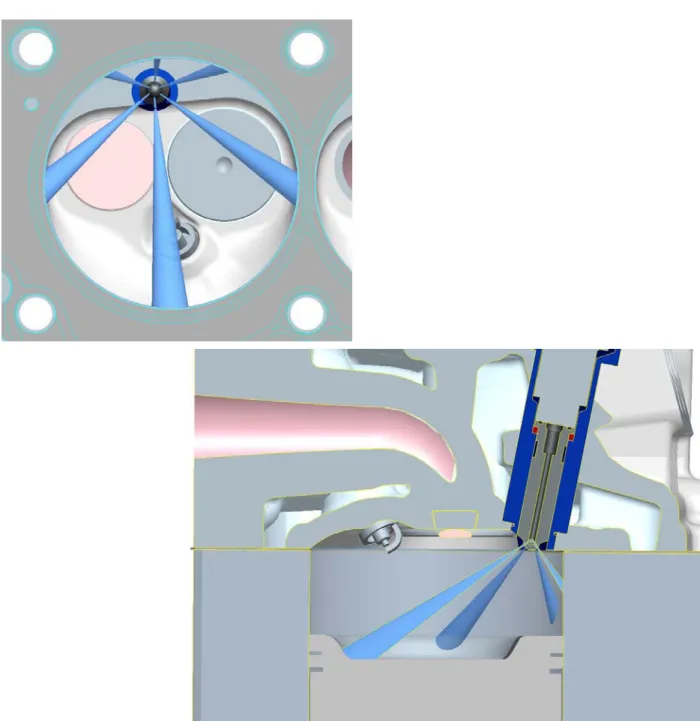
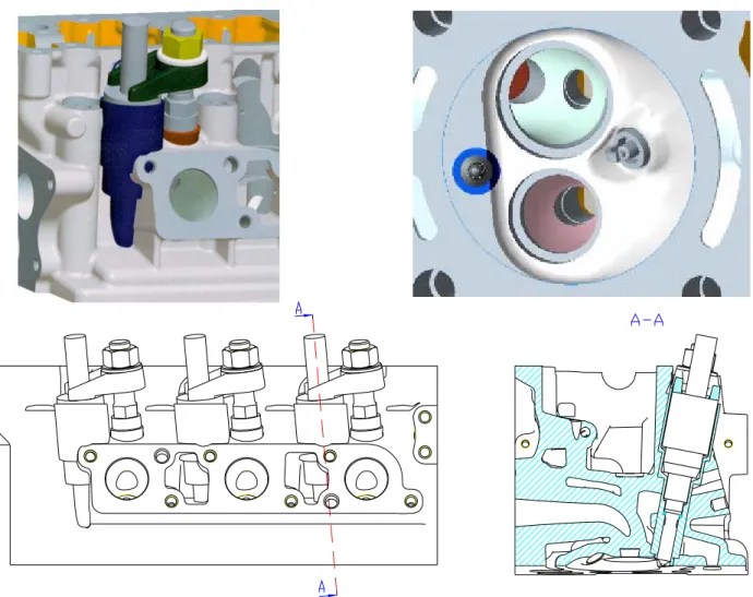
At present, this selected engine head design modification with the concurrent installation of injectors is in the process of production. The installation of injectors is shown in Fig.5. A general view of the fuel supply to injectors from a rail presently under consideration can be seen in Fig.6. Fig.7 shows an axis geometry of jets injected out of the standard injector nozzle (Fig.4).
Figure 5: Position of a high-pressure gas injector in the internal combustion engine head
Figure 6: View of the fuel supply to injectors from a rail under consideration. [5]
Obrázek 6: Pohled na uvažovaný přívod paliva k injektorům ze zásobníku (railu). [5]
5. Conclusion
The utilization of internal mixture formation may grant advantages in terms of the ability to control the combustion process and gaseous emission generation. Respecting the engine design, however, the application of the internal mixture formation is more demanding due to the installation of the injectors into the cylinder head. At the present time, the above process is being used in research projects focused on the utilization of hydrogen in internal combustion engines. It will certainly be useful to know all the benefits of this up-to-date method of mixture formation even for engines fueled by natural gas even if this approach calls for significant rearrangements concerning vehicle storage capacity and refueling infrastructure as well. Research and experimental work will be commenced in the laboratory of Technical University of Liberec at the end of 2007.
Acknowledgements
Figure 7: View of axis geometry of jets out of the injector.
Published results were acquired using the subsidization of the Ministry of Education and Science of the Czech Republic, project 1M68407700002 – Josef Božek Research Center of Engine and Automotive Engineering.
References
[1] RAU, S.: Compressed Hydrogen Storage for Vehicle Applications. In.: 1st Hydrogen Internal Combustion Engines. TU Graz, Graz 2006
[2] Data and Materials acquired from Hoerbiger Valve Tec, Vienna 2006
[3] ŠIMAN, J.: Build in high pressure injector for gas fuel into engine 1.2 dm3. Diploma work,
KVM – 351, Technical University of Liberec, 2007
[4] LAURIN, J. – HOLUBEC, R. – MAREŠ, H.: Development of a gas engine for passenger cars. In.: XXXVIII. International Conference of Departments and Work-places focused on internal combustion engines, Bratislava 2007 pp. 18. ISBN 978-80-227-2714-3
![Figure 1: An example of a gas fuel system arrangement with external sequential natural gas injection [4]](https://thumb-us.123doks.com/thumbv2/123dok_us/1407300.2688380/2.892.196.682.284.736/figure-example-fuel-arrangement-external-sequential-natural-injection.webp)
![Figure 3: High-pressure injector supplied by Hoerbiger Valve Tec [2]](https://thumb-us.123doks.com/thumbv2/123dok_us/1407300.2688380/4.892.176.695.136.420/figure-high-pressure-injector-supplied-hoerbiger-valve-tec.webp)
![Figure 6: View of the fuel supply to injectors from a rail under consideration. [5]](https://thumb-us.123doks.com/thumbv2/123dok_us/1407300.2688380/7.892.119.478.106.544/figure-view-fuel-supply-injectors-rail-consideration.webp)