by
Inance Bonsma
Thesis presented in partial fullment of the requirements for
the degree of Master of Engineering (Mechanical) in the
Faculty of Engineering at Stellenbosch University
Supervisor: Dr. M.P. Venter Co-supervisor: Dr. M. Minelli
Prof. M.G. De Angelis April 2019
The nancial assistance of the Anderson Lid Company (ALC) and the the Ministry of Foreign Aairs and International Cooperation of Italy (MAECI) towards this research is hereby acknowledged. Opinions expressed and conclusions arrived at, are those of the author and are not necessarily to be attributed to ALC and MAECI.
Declaration
By submitting this thesis electronically, I declare that the entirety of the work contained therein is my own, original work, that I am the sole author thereof (save to the extent explicitly otherwise stated), that reproduction and pub-lication thereof by Stellenbosch University will not infringe any third party rights and that I have not previously in its entirety or in part submitted it for obtaining any qualication.
April 2019
Date: . . . .
Copyright © 2019 Stellenbosch University All rights reserved.
Abstract
The Characterisation and Modelling of a Double-Layer
Dunnage Bag
I. Bonsma
Department of Mechanical and Mechatronic Engineering, University of Stellenbosch,
Private Bag X1, Matieland 7602, South Africa.
Thesis: MEng (Mech) April 2019
Dunnage bags are used to stabilize and secure cargo. Currently, the dun-nage bags available are either single-layer dundun-nage bags which are expensive or inexpensive double-layer dunnage bags. However, due to the time-consuming production of a double-layer dunnage bag, an inexpensive single-layer dunnage bag material could be a viable alternative. The aim of the project is to develop a material criterion that can nd candidate material properties that produce the same performance parameters as the current double-layer dunnage bags at the same cost. This material should provide the same properties and display the same behaviour at similar operating conditions as the original double-layer dunnage bag.
Accordingly, a material criterion, that consists of parametric mathematical models, are developed. These models are developed using load cases that the dunnage bags experiences, along with various theoretical equations that are linked and validated by experiments. Large-scale experimental case studies and smaller swatch tests are performed to determine the actual behaviour and material properties of the double-layer dunnage bags. The experimental data of the tensile tests are analysed by using constitutive modelling. Finally, to create a material criterion, a Monte Carlo Simulation is used to input material properties, based on a normal distribution. Then, the material properties are fed into a pass criterion that is used to lter various material properties while being compared to the output of the model parameters. This nally leads to correlated candidate material properties.
Uittreksel
Die Karakteriseering en Modelleering van n Dubbel-Laag
Stusak
(The Characterisation and Modelling of a Double-Layer Dunnage Bag)
I. Bonsma
Departement Meganiese en Megatroniese Ingenieurswese, Universiteit van Stellenbosch,
Privaatsak X1, Matieland 7602, Suid Afrika.
Tesis: MIng (Meg) April 2019
Stusakke word gebruik om vrag te stabiliseer en te beveilig. Tans is die stu-sakke beskikbaar in enkellaag stu-sakke wat duur is of dubbellaagstu-sakke wat goed-koper is. As gevolg van die tydrowende produksie van 'n dubbellaag stusak, word 'n goedkoper enkellaag stusakmateriaal ondersoek. Die doel van die projek is om 'n wesenlike kriterium te ontwikkel wat kandidaat materiaal ei-enskappe kan hê wat dieselfde prestasieparameters as die huidige dubbellaag stusakke teen dieselfde koste het. Hierdie materiaal moet dieselfde eienskappe verskaf en dieselfde gedrag vertoon by soortgelyke bedryfsvoorwaardes as die oorspronklike dubbellaagsak.
Gevolglik word 'n wesenlike kriterium wat uit parametriese wiskundige modelle bestaan, ontwikkel. Hierdie modelle word ontwikkel met behulp van lasgevalle wat die stusakke ervaar, tesame met verskeie teoretiese vergelykings wat deur eksperimente gekoppel en gevalideer word. Grootskaalse eksperimentele geval-lestudies en kleiner steekproewe word uitgevoer om die werklike gedrag van die dubbellaagsakke te bepaal. Die eksperimentele data van die trektoetse word ontleed aan die hand van konstitutiewe modellering. Ten slotte, om 'n wesen-like kriterium te skep, word die Monte Carlo Simulasie gebruik om insette van materiële eienskappe te stuur, gebaseer op 'n normale verspreiding. Dan word die materiaal eienskappe gevoer in 'n slaag of druip kriterium wat gebruik word om verskillende materiaal eienskappe te ltreer, terwyl dit vergelyk word met die uitset van die modelparameters.
Acknowledgements
This work would not have been possible without the nancial support of the Anderson Lid Company (ALC) and the Foreign Aairs and International Co-operation of Italy (MAECI). I am especially indebted to my supervisor, Dr. Martin Venter, at the University of Stellenbosch, who has guided me with each aspect of the project. I am grateful to all of those with whom I have had the pleasure to work with during this project, my colleagues in Bologna who spent hours in the lab to assist me and especially my co-supervisors Dr. Matteo Minelli and Prof. Maria Grazia De Angelis at the University of Bologna, in Italy. Nobody has been more important to me in the pursuit of this project than my family and loving and supportive husband. Above all, I would like to honour God for His faithfulness throughout my life.
Contents
Declaration i Abstract iii Uittreksel iv Acknowledgements v Contents viList of Figures viii
List of Tables xii
Nomenclature xiii
1 Introduction 1
1.1 Overview . . . 1
1.2 Motivation . . . 2
1.3 Objectives and Scope . . . 3
2 Background 5 2.1 Material Science Tetrahedron . . . 5
2.2 Dunnage Bags and Production Processes . . . 8
2.3 Polymeric Material and Viscoelastic Behaviour . . . 11
2.4 Constitutive Modelling . . . 14
2.5 Mathematical Modelling and Model Fitting . . . 16
2.6 Monte Carlo Simulation . . . 19
3 Methods and Materials 20 3.1 Research Design . . . 20
3.2 Layout of Material Criterion . . . 23
3.3 Setting and Materials: Tension and Permeation . . . 29
4 Experimental Results 38 4.1 Tensile Test Results . . . 38
CONTENTS vii
4.2 Permeability Test Results . . . 42
5 Dunnage Bag Load Cases 44 5.1 Load Cases Overview . . . 44
5.2 Load Case I: Ination . . . 47
5.3 Load Case II: Cyclic Behaviour . . . 48
5.4 Load Case III: Bursting . . . 51
6 Mathematical Modelling 55 6.1 Constrained Ination Model . . . 55
6.2 Reduction-In-Void Model . . . 60
6.3 Permeability Model . . . 65
6.4 Stress Relaxation Model . . . 67
6.5 Burst Model . . . 69
7 Material Criterion 73 7.1 Material Criterion Algorithm . . . 73
7.2 Monte Carlo Simulation Results . . . 77
7.3 Material Properties Analyses . . . 80
8 Conclusion 85
Appendices 87
A Tensile Tests Thread Comparison 88 B Constitutive Model Derivation 90 C Material Criterion Candidate Results 93 D Functions of the Material Criterion 98 E Data Processing Algorithm 105 F Material Criterion Coding 107
List of Figures
1.1 Double-layer dunnage bag . . . 1
1.2 Project contribution . . . 2
2.1 Material Science Tetrahedron(Yang and Tarascon, 2012) . . . 6
2.2 Emerging Systems Engineering Triangle (Yang and Tarascon, 2012) 7 2.3 Material Science Tetrahedron applied to dunnage bag . . . 7
2.4 Dunnage bag used to restrain multiple boxes in container. . . 8
2.5 Plain weave structure of polypropylene . . . 9
2.6 Ethylene chemical composition (Sperling, 2005) . . . 11
2.7 Polyethylene with small branches (Sperling, 2005) . . . 11
2.8 Stress Strain Behaviour of semi-crystalline polymers: Where (a.) brittle behaviour, (b.) ductile behaviour, (c.) necking and cold drawing, and (d.) rubber-like behaviour (Sperling, 2005). . . 12
2.9 The three phases of creep in polymers (Barrett, 2016). . . 13
2.10 Spring . . . 13 2.11 Dashpot . . . 14 2.12 Maxwell Model . . . 15 2.13 Kelvin-Voigt Model . . . 15 2.14 H-K Model . . . 16 2.15 Burgers Model . . . 16
2.16 Illustration of train-test-split method . . . 18
3.1 Overall structure of project . . . 22
3.2 Black box approach illustraion . . . 23
3.3 Material Criterion Layout . . . 26
3.4 The methodological approach of the material criterion . . . 27
3.5 Diagram of a multiple thread PP sample before it is folded into the tin sheets. The gauge length is the area of the sample that is tested, while the gripping length is the part of the sample that is folded into the tin sheets. . . 30
3.6 Multiple thread PP sample in the warp direction with grips of folded tin plate. . . 31
3.7 Diagram of the tensile test machine setup . . . 32
LIST OF FIGURES ix 3.8 Photograph of multiple-thread sample gripped between the MTS
grips . . . 33
3.9 Photograph of single thread grips . . . 33
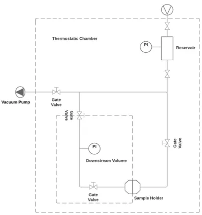
3.10 Diagram of permeation machine . . . 36
3.11 Photograph of permeation machine . . . 37
4.1 Constitutive Maxwell model . . . 39
4.2 Constitutive HK model . . . 40
4.3 Constitutive Burgers model . . . 40
4.4 Comparison between the HK model and the Burgers model when the viscosity (η1) tends to innity. . . 41
4.5 Permeability [barrer] versus Temperature [oC] comparison of the experiment versus the theoretical results (Massey, 2003) . . . 43
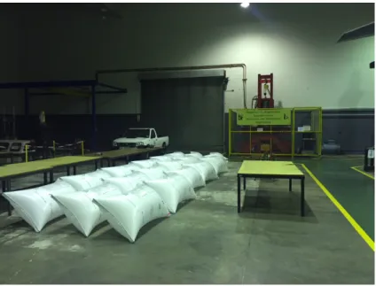
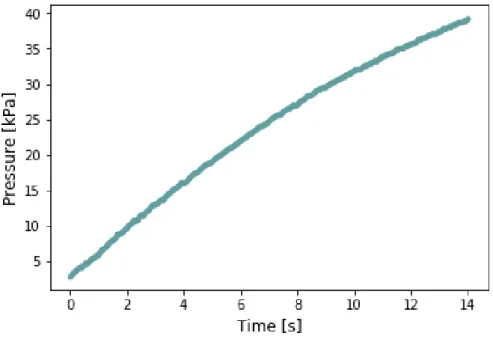
5.1 Image of the double-layered dunnage bags being preconditioned prior to testing, the hydraulic press can be seen in the background. 46 5.2 The graph shows pressure versus time for the case where the dun-nage bag is inated. . . 47
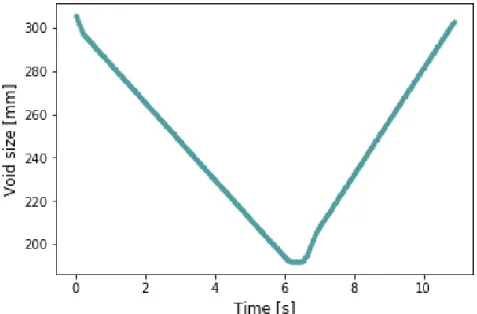
5.3 The graph shows pressure versus time for a single cycle, where the hydraulic plates lower to a 200 mm void from its' starting position of 305 mm . . . 49
5.4 The graph shows void size versus time to simulate the cyclic loading implied on the dunnage bag during transportation. . . 49
5.5 The graph shows pressure versus void size for a single cycle, where the hydraulic plates lower goes from a 305 mm void size to a 200 mm void size and back then again. . . 50
5.6 The graph shows pressure versus time where cyclic loading is im-posed on the dunnage bag. . . 51
5.7 The graph shows void size versus time where cyclic loading is ap-plied to the dunnage bag . . . 51
5.8 The graph shows pressure versus time, where the dunnage bag is compressed up to burst. . . 52
5.9 An unconstrained dunnage bag with stress concentrations near the center of the bag, where red is a high and blue is a low stress (Venter, 2011). . . 53
5.10 A constrained dunnage bag with prominent stress concentrations at the valve, where red is a high and blue is a low stress (Venter, 2011). . . 54
6.1 The tea bag simulation during the intermediate phase of ination where there exists wrinkling (Gammel, 2003). . . 56
6.2 The tea bag simulation illustrating the nal shape (Gammel, 2003). 57 6.3 The void size between the plates are assumed to be the diameter of the dunnage bag. . . 61
6.4 Reduction-in-Void Model graphs . . . 62
6.5 A ow diagram of the Reduction-In-Void Model algorithm . . . 63
6.6 Pressure [kPa] versus Void size[m] . . . 64
6.7 Comparison between the Reduction In Void model results (green line) versus the load case experiment (blue line). . . 65
6.8 A ow diagram of the Permeability Model algorithm . . . 66
6.9 Permeability Model results illustrating mass [kg] versus pressure [kPa]. . . 67
6.10 Permeability Model graphs . . . 67
6.11 Results of the Stress Relaxation Model . . . 68
6.12 A ow diagram of the Stress Relaxation Model algorithm . . . 69
6.13 Burst Model graphs . . . 70
6.14 A ow diagram of the Burst Model algorithm . . . 71
6.15 Burst Model graphs . . . 72
6.16 A comparison graph between the crush burst experimental data (blue line) and the Burst Model (green dots) . . . 72
7.1 A section ow diagram of the Main function of the material criterion. 75 7.2 A ow diagram of the MonteCarloSimulation function algorithm . . 76
7.3 Reduction in Void Model candidate material properties graphs . . . 77
7.4 Reduction in Void Model candidate material properties graphs . . . 78
7.5 Reduction in Void Model candidate material properties graphs . . . 78
7.6 Stress Relaxation Model candidate material properties graphs . . . 79
7.7 Burst Model candidate material properties graphs . . . 79
7.8 Burst Model candidate material properties graphs . . . 80
7.9 The results of the material criterion of the Reduction In Void Model 81 7.10 Correlation between E1 and E2 for all material property sets in the Reduction In Void Model . . . 82
7.11 Correlation between E1 and E2 for the passed material property sets in the Reduction In Void Model . . . 82
7.12 Correlation between E1 and E2 for the failed material property sets in the Reduction In Void Model . . . 83
7.13 Correlation between temperature and permeability for the material property sets in the Permeability Model . . . 83
7.14 Correlation between pressure and time for the material property sets in the Burst Model . . . 84
A.1 Normalised tensile test thread comparison in the warp direction . . 88
A.2 Normalised tensile test thread comparison in the weft direction . . . 89
B.1 H-K Model . . . 90
D.1 A ow diagram of the CallReductionInVoid function algorithm . . . 101
D.2 A ow diagram of the CallPermeability function algorithm . . . 102
LIST OF FIGURES xi D.4 A ow diagram of the CallStressRelaxation function algorithm . . . 104 E.1 Data Processing Alogrithm . . . 106
List of Tables
3.1 Layout of Mathematical Models . . . 25 3.2 Dimensions of a PP sample . . . 31 4.1 HK Model thread comparison with condence intervals. . . 41 4.2 Results of permeability tests whereby a comparison of temperature
vs permeability can be observed. . . 42 5.1 General experimental procedure for burst tests . . . 46 6.1 A Table showing the critical parameters used in the ination model
along with the formulas used to calculate them. . . 59 7.1 Criteria used for each mathematical model . . . 81 C.1 Reduction-In-Void Model: tensile moduli in the warp direction that
passed. . . 94 C.2 Reduction-In-Void Model: tensile moduli in the weft direction that
passed. . . 95 C.3 Permeability Model: permeation versus temperature material
prop-erties that passed. . . 96 C.4 Burst Model: critical parameters that passed. . . 97 D.1 A table displaying the functions in the Material Criterion along
with basic descriptions . . . 98
Nomenclature
Constants g = 9.81 m/s2 Variables σ Stress . . . [MPa] Strain . . . [ ] E Elastic Modulus . . . [MPa]η Viscosity . . . [MPa·s] ˙
ε Strain Rate . . . [s−1]
t Time . . . [s]
℘ Permeability . . . [sec×cmcm3×atm] D Diusion Coecient . . . [cmsec3 ]
S Solubility Constant . . . [atmcm×cm3 3]
T Temperature . . . [K]
Chapter 1
Introduction
1.1 Overview
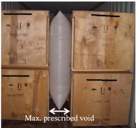
In the transportation industry there are few things as devastating as spoilt cargo. Since cargo experiences a wide range of conditions, cargo should be packed and secured in a robust manner. Hence, inatable dunnage bags are used to stabilize and secure cargo and therefore they have changed the way cargo is transported throughout the world. Most of the dunnage bags that are currently produced contain an interior airtight polyethylene (PE) bladder, which provides the inatable property, around which a woven polypropylene (PP) cover is stitched to give the bag its strength, see Figure 1.1. Although the current double-layer dunnage bags are sucient, the production of the current double-layer dunnage bags is time-consuming. An airtight PE bladder is manually placed inside a woven PP cover which is then stitched together. This task is repeated for each individual dunnage bag, which means that the production rate is highly dependent on the rate of the employees' stitching skills.
Figure 1.1: Double-layer dunnage bag 1
CHAPTER 1. INTRODUCTION 2 The aim of this project is to investigate a method of setting up a ma-terial criterion for the current double-layer dunnage bag. The intention of establishing a material criterion is to create boundaries within which candi-date single-layer materials can be discovered. The boundaries are limits and relations of material properties that result in similar behaviour as the current double-layer dunnage bags. Physical testing of the dunnage bags and swatch material testing are required to create a material criterion. Figure 1.2 presents an illustration of how this project envisions to link the physical testing, as de-ned by the Association of American Railroads (AAR) regulations, to swatch material testing. The AAR provides certication for dunnage bag by perform-ing specic large-scale experiments on the dunnage bags. The AAR focuses on the dunnage bag as a whole and not on specic material requirements. Thus, the material criterion aims to tie these two methods of testing together. Once the material criterion has been established, only swatch tests will be required to identify candidate materials that will pass the AAR tests without the need of physical testing by the AAR.
Figure 1.2: Project contribution
1.2 Motivation
The driving force behind this project is to investigate the possibility of pro-ducing an innovative product - a single-layer dunnage bag. The main criteria is to produce a dunnage bag that is more economically viable (Venter, 2016). This refers to a material that is capable of decreasing the labour time and thus increasing the rate of production.
From a business perspective, the nancial contribution that this project can add to the dunnage bag industry promotes it thoroughly. Finding a vi-able candidate material can translate to an increase in production and thus increased prot.
The process of nding a candidate material by making use of the AAR testing alone, could be a costly option. Since it will involve sourcing numerous candidate materials, then producing full dunnage bags and then testing the full bags. The production costs alone make this route unattainable since the production occurs in two-ton batches. The material criterion makes it possible to only perform large-scale testing on the original double-layer dunnage bags and then use the material criterion as an indication of the material candidacy.
1.3 Objectives and Scope
The aim of this thesis project is to develop a material criterion based on the double-layer dunnage bag. The material criterion should be established upon experimental data such that it simulates the actual load cases of the dunnage bag. Therefore specic project objectives are stated below to amplify the success of the project:
Research and establish a methodology upon which the material criterion can be created.
Conduct large-scale experiments to characterize the behaviour of the current double-layer dunnage materials.
Conduct swatch tests to determine the material properties of the current double-layer dunnage bags.
Develop a material model that can be used as a criterion to evaluate candidate materials.
Create mathematical models that simulate the loading conditions of the dunnage bags.
Use the mathematical models to nd possible candidate material prop-erties.
Communicate the results through documentation and a presentation. Since this project involves a large range of topics, the scope of the project is dened to serve as a baseline through each section of the thesis. The scope of the project is dened as follows:
The sourcing and development of new materials falls outside the scope. The range of tensile testing speeds are restricted to the ASTM
recom-mendation.
The primary and tertiary eects of creep fall outside the scope, only steady state creep and stress relaxation are considered.
CHAPTER 1. INTRODUCTION 4 The woven polypropylene material accounts for the stress relaxation and
creep, as it provides for the strength of the bag. The eects of inating a bag are disregarded.
The inside-layer of polyethylene accounts only for the permeation of the bag and not for the strength of the bag. This can be assumed since the polyethylene layer is created oversize as not to overload the inner layer.
Chapter 2
Background
In order to translate the problem statement of nding a viable alternative ma-terial (perhaps single-layer) for the current double layer mama-terial, there are numerous questions to be answered and techniques that can be followed to solve the problem. Accordingly, dierent methods to approach this multi-dimensional problem were investigated. This chapter documents the general approaches of solving interdisciplinary problems and solving open-ended ques-tions. The material that the double-layer dunnage bag consist of add another level of complexity. Polymers display distinct material properties. Hence, research was done on the properties of polymers, with specic reference to polypropylene (PP) and polyethylene (PE).
2.1 Material Science Tetrahedron
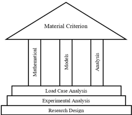
Various interdisciplinary elds are integrated in this project. Accordingly, a standard approach that incorporates mechanical engineering, materials and processing engineering, polymer science and material science is sought that interrelates and enhances the project. The traditional material science tetra-hedron (MST) is an interdisciplinary research tool that connects material sci-ence and engineering with the four areas of focus being the material structure, processing, properties and performance (Yang and Tarascon, 2012).
CHAPTER 2. BACKGROUND 6
Figure 2.1: Material Science Tetrahedron(Yang and Tarascon, 2012) Figure 2.1 illustrates a diagram of the composition of the MST. It is impor-tant to note that all four legs are connected and each aspect aects the nal design of a material. The properties and performance of the material forms part of the mechanical engineering research eld, whereas the structure of the material is evaluated within the polymer science eld. The processing forms part of the materials and processing engineering. However, the scope of this project mainly focused on the properties and performance of the material.
Figure 2.2 presents an emerging system materials engineering triangle. Yang and Tarascon (2012) explains that the systems materials engineering tri-angle shows the importance of system-level planning that starts from individual components and is followed by interface optimization. It can be observed that experiments and theory support all three legs of the triangle. Thus, all the experiments performed on the dunnage bag are based on theory. Thereafter, the experimental results are compared to theory as validation. By incorporat-ing this standard structure, a material criterion can be found. Figure 2.3 gives an illustration of the MST application to this research project and it sets the foundation to the project approach.
Figure 2.2: Emerging Systems Engineering Triangle (Yang and Tarascon, 2012) The most adequate method to support the MST strategy is to create a mathematical model that combines the physical, mechanical and barrier prop-erties. By nding mathematical relationships between the dierent elds, links are created that enable meaningful experiments. Furthermore, the experiments are divided into two categories, a mechanical case study analysis and labora-tory analysis. The mechanical case study analysis investigates the large scale physical properties of the dunnage bags whereas the laboratory analysis
CHAPTER 2. BACKGROUND 8
Figure 2.4: Dunnage bag used to restrain multiple boxes in container. tigates the material properties specically.
2.2 Dunnage Bags and Production Processes
Background on Dunnage Bags
Dunnage can be viewed as materials that are used to keep cargo in position. When a container is loaded with cargo (For example: boxes) without lling the voids between the boxes, sudden movement during conveyance can cause the cargo to move around and become damaged. However, damage to the boxes can be prevented by placing a dunnage bag between the boxes and inating the bag to the desired working pressure. Figure 2.4 presents an illustration of how a dunnage bag secures cargo.
Dunnage bags are normally used to ll a maximum prescribed void of 305 mm along with a maximum contact area of 3 m by 2 m. A dunnage bag consists of three major components, a compliant airtight bladder, a reinforc-ing cover and a non-return valve (Venter, 2015). Dunnage bags can range from level 1 to level 5. Level 1 dunnage bags are lateral void llers and they can withstand the least pressure from all the dunnage bag levels. Whereas,
Figure 2.5: Plain weave structure of polypropylene
a level 5 bag is a lengthwise void ller and it can withstand loads of up to 92 986 kg. The scope of this project involves a level 1 bag, as requested by industry partners. A level 1 dunnage bag has a more openly-packed weave material which is not as rigidly woven as the higher level bags. Thus a sample can easily unravel if it is not handled with care. Figure 2.5 presents the plain weave structure of polypropylene whereby the orthogonal material directions are warp (the machine direction) and weft (the cross direction).
The reinforcing polypropylene cover is made from plain woven polypropy-lene material which is non-linear, non-homogeneous and non-continuous. This is due to the fact that the ber architecture, matrix properties and ber prop-erties all aect the mechanical characteristics of the composite material (Dixit and Mali, 2013). The woven material is produced by interlacing two mutually perpendicular sets of yarns or threads. The threads that run lengthwise are named warp, while the vertical threads are called weft or ll. The pattern in which the warp and weft threads are interlaced denes which type of weave it has, in this case it is termed plain weave.
Dixit and Mali (2013) explain that woven materials are anisotropic, exible and have distinct viscoelastic properties (Dixit and Mali, 2013). These proper-ties indicate that the experiments may involve complex problems. In addition, Naik and Ganesh (1992) explain that the micromechanical behaviour of woven fabric laminates depends on the fabric properties, which in turn depend on the fabric structure. Various parameters are involved when determining the fabric structure, namely, weave, fabric count, bre characteristics, neness of yarn, yarn structure, degree of undulation, etc. Naik and Ganesh (1992) also describe the architecture of a woven fabric lamina as complex since there are numerous parameters involved when determining the mechanical and thermal properties of woven fabric (Naik and Ganesh, 1992).
CHAPTER 2. BACKGROUND 10 Dixit and Mali (2013) identify ber characteristics that inuence the me-chanical characteristics, namely, the ber bundles, the thread spacing, the stacking sequences, the ber orientation, the ber architecture and the ber volume fraction. However, Dixit and Mali (2013) also explicates that as a re-sult of the interlacing of the bers, woven materials oer excellent resistance to damage growth and exceptionally high values of strain at failure when in tension, compression or impact loading. Woven materials exhibit adequate di-mensional stability in both the weft and warp directions, resulting in elevated out-of-plane strengths (Dixit and Mali, 2013).
Manufacturing of Polypropylene Threads
The manufacturing of a polypropylene bag involves dierent production operations, namely, ber making, yarn making, weaving and manufacturing of the bag. Firstly, polypropylene resin is discharged into a hopper of an extruder and then heated to pass through a die to form a lm. The lm is then cooled and cut into a xed width. The slit lms are supplied continuously into equip-ment that stretches the slit lms. A hot plate heats the slit tape lm which is then stretched by high speed rollers. From this, a stretched yarn is annealed and wound on a bobbin which is delivered to weaving process. This rst stage determines the tensile strength of a woven polypropylene bag (Bags, 2014).
The weaving process proceeds by weaving the stretched yarn into a tabular state. The yarn that is drawn out from a creel stand is set on a loom in a cir-cular shape and used as a warp. When the loom is operated, a shuttle rotates in a circular motion which causes a pick to move through the warp in a circular motion causing a weaving eect. The last stage of the production process is where the woven yarn is print, cut to the desired length and transformed into a bag using cutters, printers and sewing machines (Bags, 2014).
Polyethylene Production
The polyethylene bladder is the inner layer of the dunnage bag which pro-vides for the inatable property. This inner layer is made from low density polyethylene (LDPE). The monomer of polyethylene is ethylene. The Interna-tional Union of Pure and Applied Chemists (IUPAC) name it ethene. Ethene is a gaseous hydrocarbon with the formula C2H4 that can be seen as a pair
of methylene groups (=CH2) connected to each other as illustrated in
Fig-ure 2.6. Since the compound is highly reactive, the ethylene must be of high purity. Ethylene is a stable molecule that polymerizes only upon contact with catalysts. The conversion is highly exothermic. Polyethylene is made by using several methods of addition polymerization of ethene, which is produced by the cracking of ethane and propane, naphtha and gas oil. This is a radical
polymerization process and an initiator, such as a small amount of oxygen, and an organic peroxide is used (Lazonby, 2017).
Figure 2.6: Ethylene chemical composition (Sperling, 2005)
The manufacturing process is as follows, ethene is compressed and passed into a reactor together with the initiator. The molten polyethylene is removed, extruded and then cut into granules once it solidies. The unreacted ethene is recycled. The average polymer molecule contains 4 000−40 000 carbon
atoms, with many short branches as illustrated in Figure 2.7. LDPE has a density of less than 0.930 cmg3. It has an excellent resistance to acids, bases
and vegetable oils. Additionally, LDPE also has a good combination of prop-erties for packaging applications which require heat-sealing such as toughness, exibility and transparency.
Figure 2.7: Polyethylene with small branches (Sperling, 2005)
2.3 Polymeric Material and Viscoelastic
Behaviour
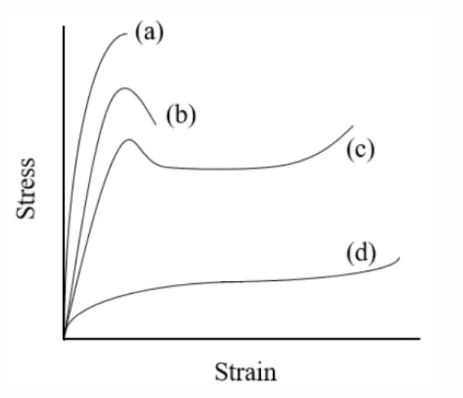
Sperling (2005) explains that polymers respond dierently to uniaxial loading, depending on their molecular strucure. The dierent responses of polymers are shown in Figure 2.8.
CHAPTER 2. BACKGROUND 12
Figure 2.8: Stress Strain Behaviour of semi-crystalline polymers: Where (a.) brittle behaviour, (b.) ductile behaviour, (c.) necking and cold drawing, and (d.) rubber-like behaviour (Sperling, 2005).
An elastic material deforms linearly proportional to the stress, when a ten-sile stress is applied, and the material instantaneously returns to its original state after the stress is removed. A viscous material elongates when a stress is applied but it does not return to its original dimensions after the stress is released. A viscous material is both time and temperature dependent. Ac-cordingly, a viscoelastic material is rate-dependent and the elasticity of the material changes depending on the rate of the loading. In general, when strain rate is rapid the response is mainly elastic. Whereas when the strain rate is slower, the viscous component of the material increases and the elastic re-sponse decreases. A material that exhibits both viscous and elastic properties when undergoing deformation is called a viscoelastic material. Materials with viscoelastic properties hold a relationship between stress and time-dependent strain.
Typical viscoelastic behaviour of polymers include:
When stress is held constant, the strain will increase with time, this is dened as creep.
is dened as stress relaxation.
The stiness of a material depends on the rate of stress application. Creep in materials can be split into three stages, Figure 2.9. In the primary stage, the strain rate decreases with time, this occur over a short period. The secondary stage has a constant strain rate. Lastly, in the tertiary stage, the strain rate increases rapidly until failure (Barrett, 2016).
Figure 2.9: The three phases of creep in polymers (Barrett, 2016). Hooke's law of elasticity states that the stress (σ) is proportional to the
strain (ε) as seen in equation (2.3.1). This property can be illustrated by a
spring, Figure 2.10.On the other hand, Newton's law of viscosity states that the stress (σ) is proportional to the strain rate (ε˙) as seen in equation (2.3.2).
This property can be illustrated by a dashpot, Figure 2.11.
σ =Eε (2.3.1)
Figure 2.10: Spring
CHAPTER 2. BACKGROUND 14
Figure 2.11: Dashpot
2.4 Constitutive Modelling
Knowing how viscoelastic material behave, the viscoelastic response can be characterized by the various equations. Roylance (2001) explains that consti-tutive modelling can be expressed as a method of developing mathematical simplications of physical behaviours that are rather complex. By combining various constitutive equations, a constitutive model is formed. A constitutive equation forms a relationship between two of material's variables. This consti-tutive equation can then approximate the response of the material to external factors (Roylance, 2001). A constitutive equation can be combined with equa-tions that are related to governing physical laws in order to solve an existing problem. Robert Hooke developed the rst constitutive equation relating the stress exerted on a material to the material's elastic response (Lautrup, 2011). Since the project aims to nd links between swatch testing and the ac-tual dunnage bag behaviour, it is essential to nd the exact parameters from a specic curve behaviour. Thus by examining the behaviour of the mate-rial with specic attention to its elasticity and viscosity, it is possible to re-late the mathematical model to various other materials without the need of testing each type of material. Furthermore, since polymers have viscoelastic behaviour, they have more than one region of elasticity, so it is essential to capture the entire behaviour of the curve. By using constitutive modelling, it is possible to input the viscosity and elasticity of a material and thus see whether a material could be suitable candidate for a single layer dunnage bag or not. The four dierent constitutive models include: (1) a Maxwell Model, (2) a Voigt-Kelvin Model, (3) a H-K Model and (4) a Burgers Model.
Maxwell Model
The Maxwell model consists of a linear elastic spring and a linear viscous dashpot element connected in a series, Figure 2.12 (Roylance, 2001).
dε dt = 1 E dσ dt + σ η (2.4.1)
Figure 2.12: Maxwell Model Voigt-Kelvin Model
The Voigt-Kelvin model consists of a linear spring element and a linear dashpot element which are connected in parallel, Figure 2.13 (Roylance, 2001).
σ=ηdε
dt +Eε (2.4.2)
Figure 2.13: Kelvin-Voigt Model H-K Model
The three-parameter H-K model, also known as the standard linear model, consists of a spring (E1) coupled in series with the Maxwell model (E2, η2),
Figure B.1 (Roylance, 2001). σ = ε 1 E1 + 1 E2(1−exp(− E2 η2t)) (2.4.3)
CHAPTER 2. BACKGROUND 16
Figure 2.14: H-K Model Burgers Model
The four-parameter Burgers model consists of two simple models, the Maxwell model (E1, η1) and the Voigt-Kelvin model(E2, η2) coupled in a series,
Figure 2.15 (Roylance, 2001).
Figure 2.15: Burgers Model
σ =E1ε 1 + E1t η1 +E1 E2 (1−exp(−E2 η2 t)) (2.4.4) It can be observed from equation(2.4.4), that if viscosity (η1) tends to
innity, the second term between brackets tends to zero, thus the Burgers model becomes the HK model, equation(2.4.3). This observation makes sense if the mechanics of the dashpot-spring model is considered. Should the dashpot (η1), which is in series with the spring (E1), become extremely viscous, the
dashpot element becomes negligible and thus only the spring and the parallel connected elements inuence the mechanics.
2.5 Mathematical Modelling and Model Fitting
Mazur (2006) explains in his article the value of mathematical models in ex-perimental analysis of behaviour. He explains that mathematical models can
make precise and important statements about behavioural processes that are relevant to anyone who is interested in explaining, predicting, or controlling behaviour, either in the laboratory or in applied settings (Mazur,2006).
Valavala (2008) used multi-scale constitutive modelling on polymer ma-terials. He explains that there are no widely accepted predictive multi-scale modelling techniques to relate micro-level properties of materials to macro-scale properties. Accordingly, he considered methods that relate engineering approaches to that of physicists. The core link is to understand both the fun-damental behaviour and properties of material. Additionally, Valavala (2008) studied the cause-and-eect relationships of parameters in order to establish an ecient modeling framework. Valavala (2008)'s modelling method was as follows, experiments were performed, than the data was carefully analysed, a model was created and compared to theory, then he created a simulation that was again compared to the experimental results (Valavala, 2008). Based on Valavala (2008)'s method of modelling materials, this project will also in-corporate theory-based experiments and combine the results with empirical mathematical models.
(Johnson, 1997) performed a study whereby an evaluation was done on the factors that eect burst test results on plastic packages. Essentially, he aimed to nd correlating parameters between burst tests and tensile tests. Three dierent ination tests were performed, namely, burst tests, creep tests, creep-to-failure tests. It was observed that the ination rate should be accurately controlled for consistent test conditions. The ination tests were performed on rigid porous packages, therefore ASTM F2054 and ASTM F1140 standards were used (Johnson, 1997).
Venter (2015) developed numerical prototypes of inatable dunnage bags whereby ination testing was used to evaluate the prototypes. The Associa-tion of American Railroads (AAR) was used as the standard for the inaAssocia-tion tests that were performed. Three dierence ination phases were identied, namely, ination, single cycle tests and ination to burst tests. These tests were performed using a large hydraulic press (Venter, 2015).
In accordance with Johnson (1997)'s methodology, this project aims to nd a correlation between burst testing and tensile testing which will form part of the material criterion. A mathematical model will be the foundation of the material criterion, whereby the dierent loading conditions will be incorpo-rated along with the swatch test experimental data. Corresponding to Venter (2015)'s methodology, the dunnage bag ination tests will be performed in line with the AAR standard, using a large hydraulic press. However, since the burst tests will be performed for a dierent application, a variation of burst tests will be performed. The aim of the ination experiments is to determine
CHAPTER 2. BACKGROUND 18 the specic parameters required in the mathematical model. These parameters include pressure, volume, void size, stress, strain and time.
With the numerous experiments that were performed, this project involves extensive data handling, therefore a reliable method of using each set of data is required to decrease the percentage error of the material criterion model. It will be a methodological mistake to learn the parameters of a predictive function and then test the function on the same set of data. This would mean that a trained model would just repetitively predict a perfect score on a value it has seen before, but it would fail to predict any other unseen data, this is called overtting. Therefore, machine learning is employed during the data analysis process of the project to avoid overtting. Machine learning can be described as the process training a model on a set of data and then testing the model on a set of unseen data and then measuring the performance of the model.
The material criterion will be created on the open source programming lan-guage, Python (the Jupyter package specically). The "scikit-learn" library provides a simplied method for applying the machine learning to the data. The train-test-split method has been employed to train the data. This method splits the data into subsets. Thus, there exists a training data set and a testing data set. Figure 2.16 illustrates the concept of the train-test-split method. The training data subsets are used to train the model. Thereafter, the testing data set is used to test the trained model. Since the testing and training data sets are two dierent data sets, the model has not seen the testing data set during the training. Using the unseen data set creates an unbias testing condition for the model.
2.6 Monte Carlo Simulation
A Monte Carlo Simulation provides a method of seeing all the possible out-comes of a specic property. This simulation method is used to provide a range of possible outcomes along with the probability that it will occur. A Monte Carlo Simulation was originally used for risk analysis. This was done by building mathematical models that simulate possible scenario outcomes. The critical parameters that inuence the outcome are substituted by ran-dom values, as a probability distribution. The simulation re-calculates the mathematical model iteratively, using the random number sets. Accordingly, a Monte Carlo Simulation provides a distribution of all the possible outcomes. Woo et al. (2005) implemented a Monte Carlo Simulation in his study on laminated plain weave composites. He determined the eect of various orien-tation angles of the weave on the elastic properties. Woo et al. (2005) used a Monte Carlo Simulation to generate random values for thread arrangements, which occur due to shift between layers. The results of his study displayed a deviation from the average value when the weave orientation tends to an angle of zero. The method he used where as follows, 1.)He generated two random numbers (rx and ry) within specied limits , 2.) Then he calculated the shift
between the layers∆xand ∆y, where∆x=rx×length and ∆y=ry×width,
3.) He modelled the sub-domain geometry for the specic shifts and orienta-tion angle, 4.) Lastly, he calculated the resulting elastic properties.
In a similar fashion, the Monte Carlo Simulation will be used in the material criterion to determine how random values of the material properties inuence the behaviour of the dunnage bag.
Chapter 3
Methods and Materials
With the background of the supporting literature in Chapter 2, it can be de-duced that this project comprises of a wide range of elds, experiments and ideas. Accordingly, this chapter is essential in understanding the chapters to follow. This chapter serves as the essence of the thesis, since it explains how every part of the project ts together. The Research Design section describes what type of research approach was followed as well as the reasons behind why certain methods were selected. In the Research Design section, the ex-periments required to build the mathematical models are also selected. In the Layout of Material Criterion section, the way that the experiments and the mathematical models interconnect are discussed along with a diagram ex-plaining the logical steps towards a completed Material Criterion. Next, the Setting and Materials section describes how the dierent experiments were de-signed and what materials were used, along with how each experiments was conducted. Then, in the Data Analysis section, the methods of how the data was processed, cleansed, evaluated and used to model the data are discussed. In this section, the constitutive modelling technique was applied to tensile data. Lastly, a summary is presented of how this chapter will be applied to the rest of the thesis.
3.1 Research Design
In the interest of designing a project with clear outcomes, the overall strategy should be chosen such that it integrates the dierent components of the project in a coherent manner. Accordingly, a suitable research style has been identied as a guideline for the project. A quantitative design is used to examine the rela-tionship between variables, where the primary goal is to analyse and represent the relationship mathematically. In a scientic quantitative research approach there are four dierent research design styles. The dierent research styles are as follows: Descriptive Design, Correlational Design, Quasi-Experimental
Design and Experimental Design (Johnson and Christensen, 2008). The De-scriptive Design technique describes the present status of a variable, whereby a hypothesis is only developed after the data is collected. The Correlational Design technique explores the relationships between parameters through a cor-relational analysis (Lappe, 2000). The idea of this design technique is to de-termine whether and to what degree the variables are related. On the other hand, the Quasi-Experimental Design technique explores a cause-and-eect relationship between variables. In this method, the results are compared with results not exposed to the control group variable. Lastly, the Experimental Design technique refers to the scientic method to nd the cause-eect re-lationship between variables. In this method, the variables are all controlled except the independent variable. Therefore, a combination between the Corre-lational and the Experimental design techniques were chosen since this makes it possible to nd correlations between parameters that have been tested exper-imentally. Numerous experimentation techniques (Experimental Design) were investigated to rstly identify the critical parameters, after which a parameter comparison and correlation (Correlational Design) were performed by making use of mathematical models. By using a combination of these two research design techniques, the hypothesis of this project is to determine whether there exists a candidate single layer material that correlates with the critical param-eters of the original double layered dunnage bag.
Once the research techniques and the hypothesis has been identied, it is possible to integrate the inter-disciplinary parameters and concepts by mak-ing use of models. Thus, dierent modellmak-ing techniques were investigated to to incorporate and interrelate these concepts and parameters. There exists mainly two methods, either Finite Element Analysis (FEA) or mathemati-cal modelling. The mathematimathemati-cal modelling approach enables relations to be formed between equations, load cases and variables. The mathematical models facilitate a core understanding of how specic parameters give specic output changes in the performance of the bag. On the other hand, by using a FEA simulation approach, the direct links between experimental data outputs and variable inputs are not that easily detected. Thus an empirical mathematical approach that results in a comprehensive material criterion was chosen. The mathematical models, that make up the material criterion, act as the agents to nd the critical parameters of the original double layered dunnage bag. Once these critical parameters (and there output behaviour) have been identied, the candidate material search is narrowed down.
Now that it has been established that a material criterion model will be used, the various concepts and parameters have to be identied and grouped to verify which experiments have to be performed. The chosen experiments have to be based on scenarios that the original dunnage bags experience. These scenarios are best described in load cases, whereby the dierent load cases can
CHAPTER 3. METHODS AND MATERIALS 22
Figure 3.1: Overall structure of project
be tested. The dierent load cases include: (1) Ination of the dunnage bag, (2) Cyclic Behaviour and (3) Bursting, see Chapter 5. During the ination process, the polymer threads experience a tensile stress as the dunnage bag becomes more inated. To test how this tensile stress inuences the ination process, the tensile behaviour of the material has to be analysed. This is done by performing tensile tests and creating a material model from the results.
Furthermore, from the time that a dunnage bag is inated until the end of its useful lifetime, the dunnage bag looses pressure. This is due to permeation of air through the material and the stress relaxation that the polymer threads experience. Accordingly, a permeation experiment was performed see what the permeability coecient is. On the other hand, a large-scale leak test was performed to see how the dunnage bag reacts. Figure 3.1 illustrates that the research design forms the basis of the project, since an inadequate design will cause the entire project to collapse. Then, the load cases form the second step which in-turn creates the basis for the small-scale experimentation. From the experimentation and the load case analysis, the mathematical models can be formulated, ultimately being combined to form a material criterion.
Figure 3.2: Black box approach illustraion
To formulate the mathematical models, certain inputs are required to pro-duces a specic outputs. However, although the specic outputs may be known, the route to the outputs may be less familiar since it requires inter-disciplinary parameters. Accordingly, Ljung (2001) explains the concept of a black box model as one that does not use specic prior knowledge of the physics of the relationships involved; Ljung (2001) describes it more as a pro-cess of "curve-tting" than "modeling", see Figure 3.2. Ljung (2001) also elaborates on this concept by dening a grey box model. This is the case where there exists some physical insight, but most of the parameters still have to be determined from observed data (Ljung, 2001). More specically, the physical insight is used to suggest combinations of the measured data signal, however the new signals are then subjected to black box model characteris-tics. Therefore, the main approach upon which the material criterion is built can be viewed as a black box model with certain aspects within being a grey box model. The data accumulated from the various experiments can be seen as the inputs. The data handling, curve-tting, mathematical equations and relationships are represented by the black box, which is the parametric box of the model. The output are various models that interrelate together to simu-late an actual double-layer dunnage bag. In the Material Criterion section this concept is explained more thoroughly.
3.2 Layout of Material Criterion
Overview
The material criterion is a technique of using information, such as operating conditions and material properties, related to the current dunnage bags to lter through candidate materials. The intention with the material criterion is to simulate how the bag should behave under specic load cases, using the elementary principles of various elds. These load cases are used to develop mathematical models that are made up of various equations and experimen-tations. This section aims to present a comprehensive layout of how each
CHAPTER 3. METHODS AND MATERIALS 24 segment of the material criterion ts into the bigger picture of the project. The material criterion starts with a series of steps that convert an output idea (the resulting candidate material properties) into a conceptual model and then into a quantitative model.
As described in Chapter 2.2, the Material Science Tetrahedron (MST) and the Systems Engineering Triangle (SET) provide adequate methods of inter-relating the various elds and methods of nding a single-layer candidate ma-terial. Instead of testing all the available single-layered materials available on the market, a systematic approach of setting up a criterion to nd the appro-priate candidate properties is followed. This is done by making use of the MST cycle, whereby theory-based experiments are performed to nd an optimized solution. This solution is established upon the four legs of the MST, such that the material properties, the dunnage bag performance, its processing and the structure of the polymeric materials are intertwined in the nal solution. The structure and processing of the dunnage bag will be evaluated upon the costs of the materials. The material properties are accounted for through experi-mentation, while the dunnage bag performance is examined by making use of the load case analysis.
Chapter 4 elaborates on the various load cases of the double-layered dun-nage bag. In brief, the dierent scenarios that the dundun-nage bag might expe-rience during a typical trip are investigated to determine how the candidate materials should perform in specic scenarios. Each load case is investigated with an experiment. With the knowledge of how the bag performs, the dier-ent segmdier-ents of the material criterion model can be set up. The load cases are used as the basis for each model within the material criterion. Accordingly, each model simulates a load case, this is done by combining scientic concepts and equations, after which the results are validated by the experimental results.
Layout of Models
Each mathematical model within the material criterion is developed such that it captures an essential segment of the dunnage bag's behaviour. In most of the mathematical models, the underlying principles and equations remain the same while the algorithms vary for the dierent load cases. Table 6 de-scribes the dierent mathematical models.
Table 3.1: Layout of Mathematical Models Mathematical Models Description
Constrained Ination Model A deated bag is inatedto 20 kPa within a 305 mm void.
Constrained Model
(Reduction in Void) A 20 kPa inated bag ispressed between two plates. Permeability Model The air permeates through thepolyethylene lm over time.
The constrained ination model is constructed to evaluate the behaviour of the dunnage bag when exposed to an increase in pressure. The Reduction in Void model is developed to see how the bag reacts to compression or cyclic behaviour, when the void size is decreased. During the inated lifetime of the dunnage bag, the air inside permeates, and the bag loses pressure. The per-meability model simulates how the air permeates through the lm, such that the pressure decreases due to the mass loss rate. The dierent temperatures also inuence the amount of permeation. Accordingly, all the mathematical models are simulated on the basis of the load cases.
With reference to the black box approach explained earlier, Figure 3.3 il-lustrates the models within the black box that are divided into the dierent mechanical load cases. The load cases are applied to the current double-layer dunnage bag. The mechanics of how the bag reacts to dierent mechanical load cases are simulated by using the material properties found from experi-ments. The data that was captured during large scale testing is used to verify the model results.
CHAPTER 3. METHODS AND MATERIALS 26
Figure 3.3: Material Criterion Layout
With the main aim of the project being to develop a material criterion for a current double-layer dunnage bag material, various aspects should be con-sidered. As mentioned in Figure 3.1, the research design, the experimental analysis and the loading conditions are the foundation steps, upon which the mathematical models are built to support the material criterion. Therefore, in order to depict the properties and behaviour of a double-layer dunnage bag the physical conditions under which the bag operates should be determined. This refers to the dierent loading conditions, temperature uctuations and pressure variations throughout a typical trip in a container. In the container, the dunnage bags experience dierent loading conditions, namely, rapid load-ing, cyclic loading and ination. During cyclic loading or rapid loadload-ing, the void size between the boxes decreases to a certain width. With reference to Figure 3.3, the geometry of the bag can be viewed more specically as the ap-proximate volume due to its' shape, discussed in Chapter 6. Since the dunnage bags display distinct viscoelastic behaviour, as time and temperature changes, the properties of the bags also change. The material properties refer to the elasticity, viscosity, permeability and durability of the dunnage bag.
Figure 3.4 provides a more detailed methodological illustration of the project overview. From the three main sections in Figure 3.4, there are two routes to-wards the parametric model, the experimental route and the theoretical route. The experimental route includes all the experiments that have to be performed to determine the material properties and loading conditions of an actual dun-nage bag. The experiments conducted include: tensile tests, permeability tests, large-scale burst tests and large-scale cyclic tests. Machine learning techniques will be employed to accurately train a model that simulates the behaviour of the PP woven threads when a tensile force is applied to it. Once the exper-imental results are analysed, it is fed into the parametric model as seen in Figure 3.4.
CHAPTER 3. METHODS AND MATERIALS 28 The theoretical route starts by constructing approximate theories that sim-ulate the viscoelastic behaviour of the PE and PP layers of the dunnage bag. The theoretical knowledge of how the material behaves dictate how the exper-imental data is analysed. Since the material displays viscoelastic behaviour, constitutive modelling has been employed to analyse the tensile tests' data, as explained in Chapter 2.5. From here the applicable equations should be sought and linked in order to join the theoretical route to the parametric model.
The dierent load cases that act on the dunnage bags during transporta-tion sets the basis for the future of the project. From here, analytical models are built using specic state variables. For each model, assumptions are made in terms of variables that are kept constant for that specic load case. To account for these assumptions, experiments are performed and the data is fed into the specic analytical models. After all the tests have been completed, all the analytical models are combined into a predictive model. This way is it possible to test the specic properties of the dunnage bags despite the many variables and still account for the assumptions. The material criterion uses a "top-down-bottom-up" approach whereby the mathematical model is cross-validated. An assumption in one experiment is accounted for by performing another experiment that includes the "external variables" from the previous experiment. Numerous experiments were performed, the data was fed into the complete mathematical model (assuming the candidate materials will have the same geometric behaviour as the current dunnage bags) and then the two complete mathematical models were compared to indicate whether the new material is a possible candidate or not.
The parametric model combines the material models with the experimental results as well as the theoretical part of the project. In the parametric model, the initial values of the model parameters are assumed and then by iterations the actual values are calculated. The parameters include volume, pressure, mass, length, void size, stress, strain and various others. From here it is pos-sible to make theoretical predictions. It should be restated that the material properties of the double-layer dunnage bag must be determined at this point. Then a normal distribution of these material properties, specically the tensile moduli, are fed into the pass criteria as possible candidate properties, which can, at later stage, direct the search to the chosen candidate single-layer ma-terial. The material properties that fail in the criteria are discarded, while the succeeding properties are fed into another iteration loop. This behaviour can then be used to compare the stress-strain curves from the actual tensile tests to the stress-strain curves produced by the parametric model.
Pass criterion
The pass criterion is based on the critical parameters of the dunnage bag, such as volume, pressure and mass. If the candidate material's properties be-have within the bounds of the critical parameters, it may be considered as a candidate material property. Materials whose properties behave outside the critical bounds are discarded.
3.3 Setting and Materials: Tension and
Permeation
3.3.1 Tensile Tests
Polypropylene has viscoelastic properties, thus more than one tensile modulus can be determined. Since the strength-providing layer of the double-layered dunnage bag is made up of woven polypropylene threads, the process of de-termining the stress-strain curve is more convoluted than standard polymers. Considering that each polypropylene thread inuences the result of the stress-strain curve, alternative methods of tensile testing were exploited.
The experimental objective was to analyse the mechanical properties of the woven polypropylene reinforcing cover and along with the polyethylene lm. Therefore, the tensile tests were used to determine the strength, the ten-sile modulus and behavioural curve of the dunnage bags. Both layers of the dunnage bag were considered. However, MatWeb (2018) compares the prop-erties of LDPE and PP, whereby the ultimate tensile strength of PP is up to four times stronger than that of LDPE. Furthermore, the moduli of elasticity of PP is more than ten times larger than that of LDPE. Accordingly, it can be assumed that the PP layer contributes the most strength and toughness of the dunnage bag and therefore only PP is considered for these properties. There are not specic standards for testing the woven polypropylene, how-ever the crosshead speed was determined by using ASTM D882, (Properties, 1995). This standard states that for a polymer with a percentage elongation of between 20 and 100%, a crosshead speed of 50 mm/min should be used. There-fore, since the typical properties polypropylene has an elongation at break of 35% (Ridderex), a 50 mm/min crosshead speed was used. Furthermore, the number of threads per sample was varied between 6 - 8 threads. It gave an indication as to what the role is that the number of threads play with regards to the mechanical properties of the specic samples. Appendix A elaborates on the comparison between the sample thread sizes. Single threads were tested at the same crosshead speed as the multiple thread samples with the aim to compare the stress that each thread can withstand. This way it was possible
CHAPTER 3. METHODS AND MATERIALS 30 to determine the relationship between a single thread and multiple threads.
Specimen preparation
Each specimen (with multiple threads) was cut to the dimensions described in Figure 3.5. A thin strip was cut from the woven PP material, at a width of 14 threads. The threads easily unravel from the specimen, thus to account for the unravelling during the specimen preparation, 14 threads are cut initially. Then two strips (25 mm width x 160 mm length) each were cut from a tin sheet. These strips (which act as the grips) were each folded into the tin sheet (25 mm x 40 mm). Thereafter, the tin sheet was unfolded and the PP strip was then glued onto the edge of the tin sheet. From here, the PP strip was folded with the tin sheet. After which, a 100 mm gauge length was measured along with the 160 mm gripping length, as illustrated in Figure 3.5. The opposite edge of the PP strip was then cut to the exact measurements and folded as with the previous tin sheet. After the PP strip and the tin sheets were attached to each, the grips were compressed with weights of 2 kg to prevent slippage between the tin grips and the woven PP strip during testing. Lastly, the 14 threads were unravelled to the desired width (6,7 or 8 threads per sample).
Figure 3.5: Diagram of a multiple thread PP sample before it is folded into the tin sheets. The gauge length is the area of the sample that is tested, while the gripping length is the part of the sample that is folded into the tin sheets. Figure 3.6 presents a photograph of a polypropylene multiple-thread sam-ple before testing. Dierent samsam-ples were produced for both weft and warp directions. Table 3.2 presents the exact dimensions of the multiple thread sam-ples. For the single thread experiments, a single thread was simply unraveled (either in the weft or the warp direction) and placed between the plated grips.
Figure 3.6: Multiple thread PP sample in the warp direction with grips of folded tin plate.
Table 3.2: Dimensions of a PP sample Description Dimensions Gripping length 40 mm Gage length 100 mm Width 25 mm Total length 180 mm Thickness 0.042 mm. Experimental Setup & Procedures
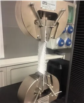
An INSTRONTM tensile testing machine with a load cell of 50 kN, MTS
grips and Bluhill acquisition software was used to perform the tensile tests. Figure 3.7 illustrates the layout of the experiment. Each test was conducted at a constant crosshead speed of 50 mm/min. For each series of tests, 7 sam-ples were prepared and tested. The software was set up such that a 3 N pre-tension was applied to each sample. Once the 3 N tension was reached the system zeroed the load and automatically started conducting the tensile test at a 50 mm/min crosshead rate. Once the specimen fails under tension, the Bluhill software automatically stopped the INSTRONTM tensile testing
CHAPTER 3. METHODS AND MATERIALS 32
Figure 3.7: Diagram of the tensile test machine setup
In order to determine which sample set accurately describes the tensile be-haviour of the PP material, the 1-, 6-, 7- and 8-thread results were compared, see Appendix A. For each specimen size, a set of at least seven specimens were tested in both weft and warp direction. The dierent thread-size samples (specimens with dierent widths) were compared since testing woven material with such an openly-packed weave presents many challenges, especially when constrained to specic gripping methods. During the tensile testing, the width of the clamps available were the limiting factor. Ideally, one would want to test a sample with the largest number of threads. Therefore, the 6-, 7- and 8-thread samples were compared to see which sample size works bests with the clamps available. The edge eects (the threads at the ends of the sample) inuence the samples. Thus, for the 8-thread samples, the threads at the ends of the sample tend to unravel or snap much quicker than with the 7-thread samples since the grips were just smaller than the 8-thread sample. Therefore, the 7-thread sample was the largest number of threads that t well with the clamp sizes available. Figure 3.8 presents a photograph of a multiple-thread test.
Figure 3.8: Photograph of multiple-thread sample gripped between the MTS grips
The single threads were tested using INSTRONTMScrew Side-Action Grips
2710 - 102 Series. These grips have a dual-action design, which means that the jaw faces can be adjusted independently. Figure 3.9 presents a photograph of the grips used for the single thread tests. With the dual-action design com-bined with at sample holders, it is essential to ensure that the line of tensile force is precisely concentric with the grip body. In addition, the force with which the single thread sample is tightened should be such that it does not damage the sample prior to testing.
CHAPTER 3. METHODS AND MATERIALS 34
3.3.2 Permeability Experiments
Permeation can be described as ow of a gas or uid through a material. The variable of permeation does not take into account the cracks or physical aws in the structure of the polymer (Ebnesajjad, 2003). Since the aws in a ma-terial inuence how the gas permeates through a mama-terial, it is essential that the material be fabricated carefully to avoid aws in the polymer material. Therefore, although a specic candidate material may be selected according to a permeation criteria, the actual performance of the material may dier to what is expected since the fabrication thereof plays a major role. The per-meation through polymeric membranes occurs by a solution-diusion model. Permeability is explained by Fick's law and is dened by,
℘=D×S (3.3.1)
where℘is the permeability of a gas [sec×cmcm3×atm],Drepresents the diusion
co-ecient [cm3
sec] and S is the solubility constant [ cm3
atm×cm3]. Acharya et al. (2004)
explains that permeation occurs in three stages, namely, sorption, diusion and desorption (Acharya et al., 2004). The sorption of gas molecules occurs at the upstream side of the membrane. Owing to the concentration gradient, molecules diuse across a membrane before they are absorbed on the down-stream side of the membrane. The ux is determined by the ow rate meter, which relates to the permeability cell that measures the permeability. Accord-ingly, permeability is also dened by,
℘= F lux×T hickness of membrane
P ressure dif f erence (3.3.2)
Ebnesajjad (2003) explains that there exist several factors that aect a polymer's rate of permeation. Temperature has a signicant eect on the permeation rate. As the temperature increases, the rate of permeation can increase for two reasons: 1.) at higher temperatures the solubility of a per-meant will increase and 2.) the polymer chains move more abundantly which allows for easier diusion of the permeant. The permeant is the gas of uid that permeates through a material. The relationship between the temperature and permeation is represented by the Arrhenius-type relationship:
℘=P0×exp − Ep R×T (3.3.3) where Ep is the activation energy of permeation. The activation energy can