Incremental High Throughput Network Traffic
Classifier
H. R. Loo
∗, Alireza Monemi
∗, Trias Andromeda
†, and M. N. Marsono
∗∗Faculty of Electrical Engineering, Universiti Teknologi Malaysia, 81310 Johor Bahru, Johor, Malaysia. †Department of Electrical Engineering, Diponegoro University, Semarang, Indonesia, 50275
Email: [email protected], [email protected], [email protected], [email protected]
Abstract—Today’s network traffic are dynamic and fast. Con-ventional network traffic classification based on flow feature and data mining are not able to process traffic efficiently. Hardware based network traffic classifier is needed to be adaptable to dynamic network state and to provide accurate and updated classification at high speed. In this paper, a hardware architecture of online incremental semi-supervised algorithm is proposed. The hardware architecture is designed such that it is suitable to be incorporated in NetFPGA reference switch design. The experimental results on real datasets show that with only 10% of labeled data, the proposed architecture can perform online classification of network traffic at 1Gbps bitrate with 91% average accuracy without loosing any flows.
Index Terms—Online incremental classification; NetFPGA; network traffic classification;
I. INTRODUCTION
Network managers use quality-of-service (QoS) manage-ment to monitor traffic classes to achieve certain quality aims such as committed access rate (CAR). They categorize network traffic into groups of critical and non-critical traffic; or business and non-business traffic in order to perform such monitoring. Network traffic classification is applied in this case to assist network managers to accomplish these network management tasks.
In order to support real-time network traffic monitoring with data rates up to hundreds of Gbps, network traffic classifiers have to be designed on hardware. Several recent works [1]– [4] proposed the implementation of network traffic classifiers that were based on flow features on field programmable gate array (FPGA) to increase classification throughput. In addition, high throughput network processing platform such as Network processing FPGA (NetFPGA) were used in [1], [2] such that extraction of flow features from network traffic can be done inline with the flow of network traffic. This is to ensure that the overall traffic classification does not become the bottleneck in the network.
However, today’s network traffic does not grow only in speed and size. The ever-changing and dynamic behavior of today’s network traffic (due to the introduction of new applications, changing in network size and protocol) could not be handled by network traffic classifiers based on batch data mining, as the classification model is fixed upon training that
Corresponding author: M. N. Marsono, [email protected]
fully rely on labeled dataset. Flow labeling is time-consuming and it could not be done accurately without human inputs. Thus, in order to handle dynamic high bandwidth network traffic, a classifier not only need to be able to perform online classification, but it also needs to update its classification model from time-to-time and able to learn from unlabeled flows.
In our earlier work [5], an incremental k-means algorithm for online network traffic classification was proposed, which is able to perform update on the classifier incrementally based on labeled and unlabeled flow. In this paper, a hardware architecture that is suitable to be incorporated in NetFPGA reference switch design [6] is proposed based on the algorithm in [5] to perform online classification for high throughput network traffic classification.
II. NETWORKTRAFFICCLASSIFICATION ONNETFPGA Monemi et al. [2] proposed a hardware network traffic classification based on decision tree algorithm on NetFPGA. The work implemented a fully working system with flow exporter and feature extraction ability in line speed on NetF-PGA Ethernet switch design. Monemi et al. [2] added a
Flow_Classifier module that consists of a flow exporter, fea-ture extractor and static classifier as an additional pipeline stage in betweenOutput_Port_LookupandOutput_Queueson NetFPGA Ethernet switch design.
In this paper, the network traffic classification architecture is proposed based on the original work done by Monemi et al. [2]. As shown in Figure 1, the proposed network traffic classifier can be used by replacing the original static classifier inFlow_Classifier.
III. ONLINEINCREMENTALk-MEANSALGORITHM
The incremental k-means classification proposed in [5] consists of two main processes: classification and learning. By using supervisedk-means technique, initial batch labeled flow instances are clustered into kinitial clusters. The clusters are then compressed to sufficient statistics known as Clustering Features, CF=<N,~µ,R~,U~,T,y> where
N : number of instances in cluster
~
µ : centroid of clusters
~
R : radius of clusters
~
U : direction of centroid change
y : class of clusters
The classification process finds the distance of incoming flow instances xi from all clusters. xi is classified as being
in the class of the nearest clusters. Flow instances with higher prediction confidence are used for incremental learning by updating its nearest cluster. At the same time, labeled flow instances are injected to the model. Outdated clusters will be removed from the classification model during the reconstruction process. Further details of online incremental
k-means algorithm can be found in reference [5]. In this paper, the Manhattan distance method is used.
IV. INCREMENTALSEMI-SUPERVISEDTRAFFIC
CLASSIFIERARCHITECTURE
The proposed classifier architecture consists of three main modules, which are the classification, incremental_learning,
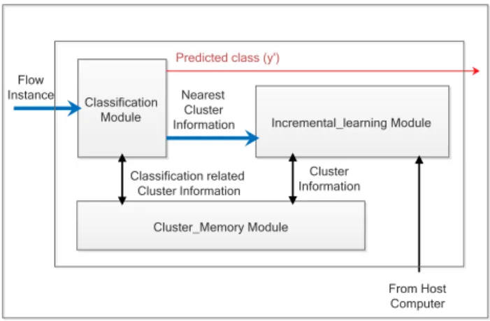
andcluster_memory modules. The classification module and
incremental learning module perform most of the processing of flow instances. They are connected to the cluster memory module that stores cluster information. Host computer can provide labeled flow instances through the register pipeline of NetFPGA platform to the incremental learning module. Figure 2 shows the top level block diagram of the incremental semi-supervised classifier architecture.
A. Classification Module
This module performs classification of incoming flow in-stances. Figure 3 shows the block diagram of the classification module. The classification module consists of a module that compares each feature of an input flow instance and cluster centroid to feed the correct input to the distance calculation pipeline. The distance_calculation_pipeline has d pipeline stages, where d is the number of features. In each pipeline stage, the absolute difference of features between the incom-ing flow instance and the cluster centroid is calculated and accumulated. The output of this module is the total distance.
Theget_nearest module is a state machine that compares the
total distance to find the cluster with the shortest distance. The module compares upon the receiving of the first valid total distance from distance calculation pipeline.
The online classifier module takes(k+d+ 4)clock cycles to complete the classification of one flow instance. k is the
Input_ Arbiter DMA from Host From Ethernet RxQ DMA to Host To Ethernet Register Bus Master
Register I/O over PCI
Registers Output_ Port_ Lookup Registers Flow_Classifier Registers Output_ Queues Registers TxQ Packet Bus Register Bus NetFPGA Semi-supervised Incremental Classification
Fig. 1: Top-level architecture high throughput network traffic classifier on NetFPGA. Classification Module Flow Instance Incremental_learning Module Cluster_Memory Module Nearest Cluster Information
Predicted class (y')
Classification related Cluster Information Cluster Information From Host Computer
Fig. 2: Incremental semi-supervised traffic classifier block diagram. Compare _Input Module Distance_Calculation _Pipeline Get_ Nearest Module Flow Instance Cluster Information Greater Smaller
Distance PredictedClass Classification Module
Fig. 3: Classification block diagram.
number of clusters in the classification module, which ranges from 64to 127for the case of kd = 64and kmax = 128. In
short, the classifier produces the predicted label between 74
and137 clock cycles after receiving the flow instance.
B. Incremental Learning Module
The incremental learning module takes its input from the online classifier module and cluster mem-ory module. This module is the only module that has both write and read accesses to the cluster memory. A FIFO is implemented to buffer the input from the classifier module as this module might need more time to process a flow instance compared to the classifier module. On the other hand, the input from the host computer are labeled instances, hence it has the priority for learning. Thus, it will not be buffered as learning is done immediately. Figure 4 shows the simplified block diagram of the incremental learning module.
1. Finite state machine (FSM) in incremental learning module controls the incremental learning process. The total learning cycles for one flow instance is dependent on the steps which it goes through, which ranges from
10to50clock cycles.
2. Nearest_Neighbormodulehas the same architecture as the classification module except that it does not produce the predicted class. It finds the nearest centroid and supplies the minimum distance and cluster information to the learning module.
FIFO Cluster Update Boundary Check Flow Instance Labeled Instance Nearest Neighbor FSM Reconstruction Write to Cluster Memory Flow Features Boundary Learning Method Cluster Information
Incremental Learning Module
Fig. 4: Incremental learning block diagram.
+ r r0=0 Boundary_Check Module r1 r2 r1 + r3 r4 r2 + r5 r6 r3 / N R > D in_boundary_1 >2 in_boundary_2
(a) Block diagram of boundary check module.
WAIT START start COMPARE FIX RADIUS N == 1 COMPARE RADIUS Y N done Y radius done N N Y S1 S2 S3
(b) Algorithmic state machine.
Fig. 5: Boundary check module.
3. Boundary_Check moduleis made up of two parts. The first part is to calculate the radius of the nearest cluster and compare with the distance, while the second part is to compare with fix boundary R= 2 when N = 1. Figure 5 shows the block diagram and algorithmic state machine (ASM) for FSM of this module.
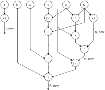
4. Cluster_Update modulecomputes the new cluster fea-tures CF including updating the timestamp. Figure 6 shows the ASM of this module. The state machine checks on the confidence level and whether a new cluster has been created. Figure 7 shows the data flow graph to update the components inCF=<N,~µ,R~,U~,T,y>. The critical path delay happens when calculating for new radius. This module applies serial processing at features level as the hardware resources are limited in NetFPGA and most of the resources are allocated for online
clas-WAIT_START start L0 or new cluster CALCULATE _CF Y N done Y radius_done N S1 S2
Fig. 6: Algorithmic state machine for cluster update module.
R u x m N | - | * +1 + / / | - | * + N_new m_new R_new t +1 t_new
Fig. 7: Data flow graph ofCF update.
sifier module to maximize its throughput. Each group calculation is repeated d times. Hence it will take up the most clock cycles in the whole incremental learning process, which is5d+ 1 clock cycles to complete one process. When injecting a new cluster or replacing a current cluster with a new cluster, it only needs1 clock cycle.
5. Reconstruction moduleconsists of a FIFOkmaxdeep.
Figure 8 shows the block diagram of reconstruction module. Clusters with t 6= 0will be copied into FIFO from cluster memory andtis decremented by one. The process will continue by removing t= 0 clusters from FIFO until there is only kd cluster in the FIFO. The
read from memory
Cluster
Memory
write to memory total == kd
FIFO t != 0 t == 0 discard total > kd check t Reconstruction Module
Fig. 8: Reconstruction module.
module will write all clusters in the FIFO back to cluster memory and push empty cluster back to cluster memory for the cluster addresses fromkd+ 1 tokmax.
During the reconstruction process, all inputs from the labeled module will not be processed and all outputs from the online classifier module will be buffered in its FIFO. This process does not affect the online classifier module as it processes in parallel. However, the writing process will take kmax clock cycles and it may cause
false classification for those flow instances being classi-fied during the update process. Since the reconstruction does not happen frequently, false classification on one flow instance is very rare.
This implementation is different from the original pro-posed method in [5], where the number of clusters is unbounded, which is an unwanted scenario as it will consume high hardware resources. Thus, this part of the algorithm is modified to dynamic method where the number of clusters in the classification model is constantly being observed. Once the total number of clusters reach the maximum number of clusters kmax,
reconstruction will be initiated.
C. Cluster_Memory Module
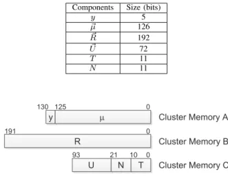
The cluster memory module is used to store cluster in-formation that is CF=<N,~µ,R~,U~,T,y> up to the number of maximum cluster,kmax. In this paper,kmax is set to128. A
total of 417 bits are needed to store one cluster information, where the size allocation of each variable is listed in Table I. As it is huge, having them as a whole will complicate the synthesis process. Thus, the cluster information is divided into three units. The first unit, cluster_memory_A, consists of y and µ that are the necessary information used by both the classification and incremental learning modules. This unit is built to have one input and two outputs as it will only be written by the incremental learning module, while it can be read by both online classifier and incremental learning modules. An additional bit is added incluster_memory_A to show the validity of cluster in that memory location. This bit is important to the classifier as it acts as the indicator on which memory location has valid cluster information as the number of clusters is not static.
TABLE I: Size allocation of components in the cluster infor-mation
Components Size (bits)
y 5 ~ µ 126 ~ R 192 ~ U 72 T 11 N 11 y m R U N T Cluster Memory A Cluster Memory B Cluster Memory C 0 125 130 0 0 191 93 21 10
Fig. 9: Cluster memory bit allocation.
Cluster_memory_B and cluster_memory_C modules have
one input and one output. Cluster_memory_B stores the information of R~ and cluster_memory_C stores the rest of the cluster information. Both cluster memories can only be accessed from the incremental learning module. The bits allocation of cluster memory module is in Figure 9.
V. RESULTS ANDANALYSIS
This section discusses the overall performance of the pro-posed architecture. The percentage of labeling is assumed to be P = 10%.
A. Datasets
Two real network traffic datasets UNIBS [7] and PAM [8] are chosen for the experiment. The UNIBS dataset [7] was captured in University of Brescia for three consecutive days from 30th September 2016 to 2nd October 2016. A total of 77,303 flows are extracted. By using the provided groundtruth labels, the flows are labeled into five classes, namely Web,
Mail,P2P,SKYPE, andOthers.
The PAM dataset [8] was captured in Aalborg University from 25th February 2013 to 1st May 2013. A total of 339,061 flows are extracted from these datasets. By using the provided information files, the flows are labeled into four classes, namely WEB,FTP,P2P, andOthers. In this work, all traces are processed using flow exporter and feature extractor based on 1 minutes timeout where flows that have five packets or more are extracted. Table II summarizes the datasets and Table III shows the selected online features for classification.
TABLE II: Dataset used.
UNIBS [7] PAM [8]
# flow features 12 12
# classes 5 4
TABLE III: List of online features selected for online classi-fication.
ID Name Long Description
01 TL IP Total bytes in IP packet
02 UL IP Total bytes in IP packet (uplink)
03 DL IP Total bytes in IP packet (downlink)
04 TL Eth Total bytes in Ethernet packet
05 UL Eth Total bytes in Ethernet packet (uplink)
06 DL Eth Total bytes in Ethernet packet (downlink)
Classification Incremental Learning t f 1 f 1 f: flow instance f 2 f 2 (a) Classification Incremental Learning t f 1 f 2 f 1 f 2 f: flow instance f 3 (b)
Fig. 10: Difference of online classification and incremental semi-supervised learning process waveform for a) interleave-test-then-train and b) simultaneous test-and-train method.
B. Accuracy
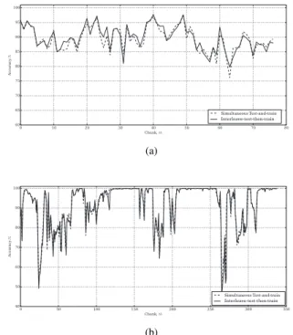
In this section, the accuracy of the incremental semi-supervised classifier is measured using testbench that is vali-dated in Modelsim in two simulation setups. The first setup is the interleave-test-then-train method where new incoming flow instance is assumed to arrive after learning has been done. The second setup is the simultaneous-test-and-train where new incoming flow instances arrive back-to-back before the learning is done. Both simulation setups are illustrated in Figure 10.
Figure 11 shows the network traffic classifier’s accuracy comparison between the interleave-test-then-train method and simultaneous-test-and-train method. The result shows that the classifier maintain similar accuracy in both setups. The average accuracy for both dataset are 90.09% and 91.80% for UNIBS and PAM datasets, respectively.
C. Overall Throughput
The performance of the online incremental semi-supervised learning network traffic is shown in Table IV. In this paper, the overall throughput, Toverall metric as proposed in [4] is
used. The throughput is calculated in terms of total number of classifications done per unit time by the classifier hardware architecture. The measurement is in Million Classifications per
Simultaneous Test-and-train Interleave-test-then-train (a) Simultaneous Test-and-train Interleave-test-then-train (b)
Fig. 11: Accuracy comparison between interleave-test-then-train and simultaneous test-and-interleave-test-then-train online and incremental semi-supervised learning network traffic classification for a) UNIBS and b) PAM datasets.
second (MCps). Given Nc is the total number of
classifica-tions,Tcis the total clock cycle used andfc is the clock rate,
the calculation of throughput is defined as follow:
Toverall=
Nc∗fc
Tc
(1) The proposed hardware architecture can work within the clock rate of NetFPGA 1G reference design’s 64-bit pipeline datapath clock rate which is 125 MHz. Thus, the overall throughput of the proposed classifier is at least 1.16 Million Classification per second (MCps), which results in less than 0.9µs classification time for each flow instance classification. Assuming that flow exporter is embedded in a network pro-cessing platform and feature extraction is able to process in line speed as shown by Monemi et al. [2], the online classifier is able to classify a flow in less than 1.6µs for 1Gbps line rate. This is calculated based on the worst case scenario where a flow with empty-payload packets arrive back-to-back. As the proposed method takes the first 5 packets statistic information from the first five packets, the shortest inter-arrival time for two flows is 1.6µs (i.e.,40bytes1Gbps∗5packets). This clearly shows that the proposed hardware network traffic classifier can perform online classification in which all flow instances can be classified upon arrival.
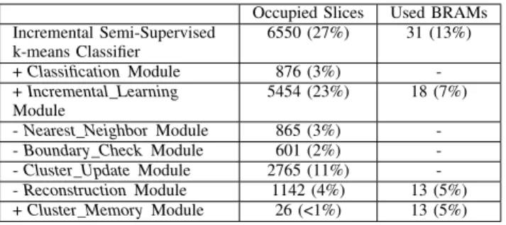
D. Resource Consumption
The proposed architecture occupies 27% of the available slices in Virtex 2-pro. Table V shows the detail breakdown of hardware resource utilization of each module. The incremental
TABLE IV: Overall performance for online and incremental semi-supervsied learning network traffic.
Dataset UNIBS PAM
Total flow instance 77,303 339,061
Total clock cycle used 8,310,785 35,701,463
Average clock cycle per flow instance 108 106
Overall throughput (at 125MHz clock rate) 1.16 MCps 1.19 MCps
Average classification time 0.864µs 0.848µs
TABLE V: Hardware resources utilization.
Occupied Slices Used BRAMs
Incremental Semi-Supervised k-means Classifier 6550 (27%) 31 (13%) +ClassificationModule 876 (3%) -+Incremental_Learning Module 5454 (23%) 18 (7%) -Nearest_NeighborModule 865 (3%) --Boundary_CheckModule 601 (2%) --Cluster_UpdateModule 2765 (11%) --ReconstructionModule 1142 (4%) 13 (5%) +Cluster_MemoryModule 26 (<1%) 13 (5%)
learning module uses almost 8× more resources than the
classification module. Thecluster_update module utilizes the highest portion of consumed resources. This is due to the use of many large registers in the pipeline calculation to update the cluster information. Apart from that, the reconstruction
module takes up a large portion of resources especially the Block Random Access Memory (BRAM) used. This is due to the number of a FIFO to temporarily store the cluster’s information for processing that has the same size as thecluster
memory module.
Referring to the occupied slices report in reference [2], the total occupied slices for the decision tree network traffic classifier is 77%, while the decision tree classifier used 8% of the total resources. The proposed hardware architecture can be implemented on the same platform by replacing the classifier module.
E. Discussion
The architecture is synthesized in Virtex 2-pro FPGA and targeted on NetFPGA 1G reference design. NetFPGA 1G reference design has the time constraint of 8µs per cycle for the user data path pipeline module. Virtex 2-pro FPGA has limited hardware resources especially the number of slices. In addition, the reference Ethernet Switch design [6] in NetFPGA occupies nearby 50% of the hardware resources. Hence, only limited slices can be used for additional functionalities. This limits the performance of the proposed classifier.
To improve the current architecture, more advanced plat-form such as NetFPGA 10G that comes with Virtex 5 FPGA can be used. With more hardware resources avail-able, more functions can be made as parallel computation modules. For example in the classification module, the dis-tance_calculation_pipelinecan be duplicated in parallel so that the time needed to find the nearest distance can be reduced by half. Besides, the same method can be applied to the cluster update module so that the time to update can be improved.
VI. CONCLUSION
This paper discusses the realization of online network traffic classifier that is based on incremental semi-supervised classi-fication algorithm proposed in [5] on FPGA. The results show that the proposed hardware architecture is able to perform online classification at 1Gbps bitrate without dropping any flows. The results also show that by having back-to-back classification does not have significant effect on the overall accuracy. Although the proposed architecture uses up 27% of hardware resources, it shows the implementation of the proposed algorithm on networking platform is possible. In future, the architecture will be implemented in an upgraded NetFPGA version to improved the classification performance.
ACKNOWLEDGMENT
The first author is funded by Universiti Teknologi Malaysia (UTM) Zamalah schorlaship. This work is funded by Ministry of Science, Technology, and Innovation of Malaysia Science Fund grant (UTM vote no. 4S095) and UTM Grant (UTM vote no. 00M75).
REFERENCES
[1] Canini, M., Li, W., Zadnik, M. and Moore, A. W. Experience with
high-speed automated application-identification for network-management.
Proceedings of the 5th ACM/IEEE Symposium on Architectures for Networking and Communications Systems. ACM. 2009. 209–218. [2] Monemi, A., Zarei, R. and Marsono, M. N. Online NetFPGA Decision
Tree Statistical Traffic Classifier. Computer Communications, 2013.
36(12): 1329–1340.
[3] Groleat, T., Arzel, M. and Vaton, S. Stretching the edges of SVM traffic
classification with FPGA acceleration.IEEE transactions on network and
service management, 2014. 11(3): 278–291.
[4] Qu, Y. R. and Prasanna, V. K. Enabling High Throughput and
Virtu-alization for Traffic Classification on FPGA. 2015 IEEE 23rd Annual
International Symposium on Field-Programmable Custom Computing Machines (FCCM). IEEE. 2015. 44–51.
[5] Loo, H., Joseph, S. and Marsono, M. Online incremental learning for
high bandwidth network traffic classification. Applied Computational
Intelligence and Soft Computing, 2016. 2016: 13.
[6] Lockwood, J. W., McKeown, N., Watson, G., Gibb, G., Hartke, P., Naous, J., Raghuraman, R. and Luo, J. NetFPGA–an open platform for
gigabit-rate network switching and routing. Microelectronic Systems Education,
2007. MSE’07. IEEE International Conference on. IEEE. 2007. 160–161. [7] Gringoli, F., Salgarelli, L., Cascarano, N., Risso, F. and Claffy, K.
GT: Picking up the Truth from the Ground for Internet Traffic. ACM
SIGCOMM Computer Communication Review, 2009. 39: 13–18. [8] Carela-Español, V., Bujlow, T. and Barlet-Ros, P. Is our ground-truth for
traffic classification reliable? International Conference on Passive and