University of Connecticut
OpenCommons@UConn
Doctoral Dissertations University of Connecticut Graduate School
12-15-2017
Advanced Power Loss Modeling and Model-Based
Control of Three-Phase Induction Motor Drive
Systems
Yiqi Liu
University of Connecticut - Storrs, [email protected]
Follow this and additional works at:https://opencommons.uconn.edu/dissertations
Recommended Citation
Liu, Yiqi, "Advanced Power Loss Modeling and Model-Based Control of Three-Phase Induction Motor Drive Systems" (2017). Doctoral Dissertations. 1669.
Advanced Power Loss Modeling and Model-Based Control of Three-Phase Induction Motor Drive Systems
Yiqi Liu, Ph.D.
University of Connecticut, 2017
Three-phase induction motor (IM) drive systems are the most important workhorses of many industries worldwide. This dissertation addresses improved modeling of three-phase IM drives and model-based control algorithms for the purpose of designing better IM drive systems. Enhancements of efficiency, availability, as well as performance of IMs, such as maximum torque-per-ampere capability, power density, and torque rating, are of major interest.
An advanced power loss model of three-phase IM drives is proposed and comprehensively validated at different speed, load torque, flux and input voltage conditions. This model includes a core-loss model of three-phase IMs, a model of machine mechanical and stray core-losses, and a model of power electronic losses in inverters. The drive loss model shows more than 90% accuracy and is used to design system-level loss minimization control of a motor drive system, which is integrated with the conventional volts-per-hertz control and indirect field-oriented control as case studies. The designed loss minimization control leads to more than 13% loss reduction than using rated flux for the testing motor drive under certain conditions. The proposed core-loss model is also used to design an improved model-based maximum per-ampere control of IMs by considering core losses. Significant increase of torque-per-ampere capability could be possible for high-speed IMs. A simple model-based time-domain fault diagnosis method of four major IM faults is provided; it is nonintrusive, fast, and has excellent fault sensitivity and robustness to noise and harmonics. A fault-tolerant control scheme for sensor failures in closed-loop IM drives is also studied, where a multi-controller drive is proposed and uses different controllers with minimum hand-off transients when switching between controllers. A finite element analysis model of medium-voltage IMs is explored, where electromagnetic and thermal analyses are
co-Yiqi Liu – University of Connecticut, 2017
simulated. The torque rating and power density of the simulated machine could be increased by 14% with proper change of stator winding insulation material.
The outcome of this dissertation is an advanced three-phase IM drive that is enhanced using model-based loss minimization control, fault detection and diagnosis of machine faults, fault-tolerant control under sensor failures, and performance-enhancement suggestions.
i
Advanced Power Loss Modeling and Model-Based Control of Three-Phase
Induction Motor Drive Systems
Yiqi Liu
B.S., Central South University, 2012
M.S., University of Connecticut, 2016
A Dissertation
Submitted in Partial Fulfillment of the Requirements for the Degree of
Doctor of Philosophy at the
University of Connecticut
ii
Copyright by
Yiqi Liu
iii
APPROVAL PAGE
Doctor of Philosophy Dissertation
Advanced Power Loss Modeling and Model-Based Control of Three-Phase Induction Motor Drive Systems Presented by Yiqi Liu, B.S., M.S. Major Advisor ________________________________________________________________________ Ali M. Bazzi Associate Advisor _____________________________________________________________________ Yang Cao Associate Advisor _____________________________________________________________________ Sung-Yeul Park Associate Advisor _____________________________________________________________________ Krishna R. Pattipati University of Connecticut 2017
iv
To My Mother and Father Shaoying Gao and Aizhong Liu
v
ACKNOWLEDGMENTS
My greatest appreciation goes to my advisor, Prof. Ali M. Bazzi, for his tremendous
support and guidance in my academic and personal lives. I am sincerely grateful to him for
trusting me and giving me the opportunity to join his lab in the summer of 2013, when I was still
a beginner in the area of power electronics and electric motor drives, and was helpless as a Ph.D.
student without any financial support in a foreign country. I am learned from him not only how
to be a good researcher, but also how to be a good instructor, leader, teammate, scholar,
presenter and writer. I am indebted to Prof. Bazzi for his instruction and suggestions during the
development of my knowledge, skills, research and working habits, independent thinking,
determination, responsibilities and communication techniques.
My gratitude also goes to Prof. John E. Ayers who accepted me to the University of
Connecticut (UConn) and was my first advisor before Prof. Bazzi. I am grateful to him for being
very nice and helpful during my first year in UConn, and kindly agreeing me to change the
advisor and research group after his illness. I am also thankful to Prof. Helena Silva for many
warmly conversations in my most difficult first year in UConn.
I am grateful to all the other committee members, Prof. Yang Cao, Prof. Sung-Yeul Park
and Prof. Krishna R. Pattipati, for their valuable suggestions to make my work and this
dissertation better. I appreciate the work opportunity with Prof. Cao on a Navy project, where I
can be exposed to finite-element-analysis modeling, insulation materials, and high-voltage
testing. I am also thankful to Prof. Park for the knowledge that I learned in his Power Electronics
and Power Conditioning System courses.
I would like to thank all my friends at UConn. They give me lots of colorful and
delightful memories. My special thanks are delivered to Gaopeng Cai who acts as a little brother
vi
Anitu Fu, Lingyi Zhang, Shu Wan, Lam Dinh, Jesse Garrard, Jonathan Rarey, Matthew
Maddocks, Julio Yela, Javier Martinez, Jose Nieto as well as Xinran Zhu, Lijie Wu, Zhe Wang,
Le Yu, Wenxin Wang, Zhiyang Jia, Tuoxi Wu, Guilin Wu, Weijie Chen, Shuzhong Cui, Hui
Zhang, Qinqing Liu, Jingwei Huang, Qizhou Wang, Lingyu Ren, Yuxin Liu, Chen Wang, Yin
Ma, Xingxu Lu for their company. I am very thankful to Zhuoer Zhou, Qingyijun Zhou, Jiemei
Luo, and Zhang Shen who are my lifelong friends and have profound effects in my growth. I also
appreciate the help from my colleagues, undergraduate assistants and staff in the Advanced
Power Electronics and Electric Drives Lab (APEDL), Department of Electrical and Computer
Engineering, and Center for Clean Energy Engineering at UConn, especially Weiqiang Chen,
Artur Ulatowski, Michael Stettenbenz, Bryan Davis, Amy Robinson and Patrick Vicente. I
would like to thank the United Technology Corporation, Office of Naval Research, and UConn
for their generous financial support.
Last but not the least, my deepest appreciation and gratitude go to my beloved parents. I
can fearlessly chase my dream and take challenges since I know there is always a warmly harbor
that I can go back to. This degree is the best gift to my mother who has devoted countless time
and energy to raise me up. She is my most loved person in the world. To my father, he is a great
friend and sets the example of responsibility to family. He is very open-minded and always
encourages me to do what I want to do. I am thankful to my dearest grandmother who spent lots
of time with me in my childhood. I am very indebted to my parents for their selfless love. I will
vii
TABLE OF CONTENTS
CHAPTER 1 ... 1 INTRODUCTION ... 1 1.1 Overview ... 1 1.2 Problem Statement ... 4 1.3 Research Statement ... 4 CHAPTER 2 ... 6 LITERATURE REVIEW ... 62.1 Modeling of Losses in Three-Phase IMs... 6
2.2 Loss Minimization Control of Electric Motor Drives ... 9
2.3 Fault Detection and Diagnosis of IMs And Fault-tolerant Control of IMs with Sensor Failures ... 13
2.3.1 Fault Detection and Diagnosis of IMs ... 13
2.3.2 Fault-tolerant Control of IMs with Sensor Failures ... 21
CHAPTER 3 ... 24
ADVANCED POWER LOSS MODELING OF THREE-PHASE INDUCTION MOTORS ... 24
3.1 A General Analytical Three-Phase IM Core-Loss Model in the Arbitrary Reference Frame ... 24
3.1.1 Derivation of the qd0-frame Forms of the Proposed Model and Loss Expressions 26 3.1.2 Parameters of the Proposed Core-Loss Model... 34
3.1.3 Simulation Verification of the Proposed Core-Loss Model ... 35
3.1.4 Experimental Validation of the Proposed Core-Loss Model ... 37
3.1.5 Parameter Sensitivity and Adaptation of the Proposed Core-Loss Model ... 47
3.2 Modeling of Mechanical and Stray Losses ... 51
3.2.1. Description of the Experimental Tests ... 52
3.2.2. Experimental Results and Discussion... 53
3.3.3. Modeling of Mechanical Loss and Stray Loss ... 56
3.3 Summary ... 58
CHAPTER 4 ... 59
MODEL-BASED EFFICIENCY AND PERFORMANCE ENHANCEMENT OF THREE-PHASE INDUCTION MOTORS AND IM DRIVE SYSTEMS ... 59
4.1 Model-based LMC of IMs Using the Proposed Core-loss Model ... 59
viii
4.1.2 Loss Minimization Control for the Open-loop V/f Control ... 67
4.2 System-level Model-based Loss Minimization Control of IMs Drives ... 71
4.2.1 Modeling of Power Electronics Losses in Three-Phase Inverters ... 72
4.2.2 LMC of IFOC-Controlled Inverter-fed Motor Drives ... 78
4.2.3 LMC of V/f-Controlled Inverter-fed Motor Drives ... 81
4.2.4 Experimental Verification of the Proposed LMC for Inverter-Fed Motor Drives.. 83
4.3 Improved Maximum Torque-per-Ampere Control of IMs by Considering Core loss ... 87
4.3.1 Derivation of the Proposed MTPA Control ... 88
4.3.2 Improvement of the Torque-per-Ampere Capability Using the Proposed MPTA Control ... 89
4.3.3 The Applicable Range of the Proposed MTPA Control ... 93
4.3.4 Design of the Improved MTPA Controller ... 94
4.3.5 Simulation Verification and Results ... 95
4.4 Summary ... 99
CHAPTER 5 ... 101
ADVANCED MODEL-BASED FAULT DIAGNOSIS AND FAULT-TOLERANT CONTROL OF THREE-PHASE IM DRIVE SYSTEMS ... 101
5.1 Adaptive Modulation Time-Domain Fault Diagnosis of Three-Phase IMs ... 101
5.1.1 Methodology ... 101
5.1.2 Simulation Verification ... 106
5.1.2 Experimental Verification ... 109
5.2 High-Performance Synchronous-Frame Multi-Controller Drive for Fault-Tolerant Control of IMs with Sensor Failures ... 112
5.2.1 Synchronous-Frame Controllers in the Proposed Multi-Controller Drive ... 114
5.2.2 Synchronous-Frame Multi-Controller Drive with Smooth Transition Between Controllers ... 119
5.2.3 Simulation Verification of the Proposed Drive and Smooth Transition Between Different Controllers ... 123
5.2.4 Experimental Verification of the Proposed Drive and Smooth Transition Between Different Controllers ... 127
5.3 Summary ... 133
ix
EFFICIENCY AND PERFORMANCE ENHANCEMENT OF THREE-PHASE INDUCTION MOTOR DRIVE SYSTEMS BY MATERIALS: ROTOR BAR AND STATOR WINDING
INSULATION ... 134
6.1 A Comparison of Rotor Bar Material of Squirrel-Cage IMs for Efficiency Enhancement Purposes ... 134
6.2 Torque Enhancement and Re-rating of Medium-Voltage IMs Using Nano-structured Stator Winding Insulation ... 140
6.1.1 Multi-Physics Finite-Element-Analysis Simulation ... 141
6.1.2 Simulation Results ... 148
6.1.3 Machine Re-Rating Process and Results ... 150
6.3 Summary ... 151
CHAPTER 7 ... 153
CONCLUSIONS AND CONTRIBUTIONS ... 153
LIST OF PUBLICATIONS ... 157
APPENDIX A ... 159
THE NUMERICAL SWEEP USED FOR LMC OF V/f-CONTROLLED IMS ... 159
APPENDIX B ... 162
THE NUMERICAL SWEEP USED FOR LMC OF IFOC-CONTROLLED IM DRIVES ... 162
1
CHAPTER 1 INTRODUCTION 1.1Overview
With the development of semiconductor devices, power electronic converters, electric
machines, and machine control, inverter-fed electric motor drive systems have become the
workhorse of the modern industry. They are widely used in various industrial, residential and
commercial applications, such as in drilling, pumping, propulsion, heating, ventilation and
air-conditioning systems, manufacturing processes and others [1]–[4]. Moreover, due to the
increasing interests in vehicular electrification and the use of clean energy in micro-grid systems,
such as using doubly-fed induction machines in wind power generation, utility of electric motor
or generator drive systems in these applications has been significantly growing [5]–[8].
An electric motor drive system typically consists of four parts: source, power electronic
drive, machine and load. As shown in Fig. 1, the source can be DC or AC in the single-phase,
three-phase or higher-phase form. The drive is the “brain” of the system, which has a low-power
control stage and a high-power energy conversion stage. This work specifically focuses on
three-phase induction motor (IM) drive systems, which are the most commonly used. Compared to
other electric motors, three-phase IMs are simple, robust and easy to control. They do not rely on
rare-earth materials and thus are low-cost compared to permanent magnet synchronous machines
(PMSMs). They also have a smoother torque response and lower torque ripple than switched
reluctance machines (SRMs).
Due to the popularity and wide use of three-phase IM drive systems, improving the
system’s efficiency, reliability, and performances, e.g. power density and torque rating, are of
2
account for more than 40% of the global electricity consumption [9], [10]. Three-phase IM drive
systems are one of the largest single energy consumers. Therefore, increasing their efficiency is
important for reducing global energy consumption and operating costs, as well as for reducing
greenhouse gas emission and for environmental protection.
Fig. 1. Block diagram of electric motor drive systems
IMs are designed of highest efficiency at rated operating condition. However, their
efficiency could drop significantly at other operating conditions at rated flux. Typical
relationships between motor efficiency and load conditions for IMs of different ratings are
shown in Fig. 2 [11]. It is seen that considerable room for efficiency enhancement is available at
low loads. Moreover, larger IMs tend to have higher efficiency and thus less room for efficiency
enhancement in percentage. However, the same percentage increase of efficiency of large IMs
can be converted to larger absolute values of energy savings. Model-based loss minimization
control is convenient to integrate with the conventional control algorithms designed for speed
and/or torque control. Properly modeling machine mechanical and stray losses, which are
commonly ignored in the power loss model of electric motors, and nonlinear core loss are
important to increase the accuracy of the model-based loss minimization control. Since the
optimal operating point of an overall motor drive system, i.e. motor and drive combined, can be
different from that of an individual motor or a drive [12], creating a system-level power loss
model of IM drives is important to guarantee efficiency enhancement of the overall system. This
3
as well as conduction and switching power electronic losses in the drive. The model has to be in
a properly unified form for the design of loss minimization control.
Fig. 2. T ypical efficiency of IMs with respect to load [11]
Fault detection and diagnosis as well as fault-tolerant control of IM drives are important
to avoid catastrophic failures, shutdown, associated repair and operational costs, etc., especially
for safe-critical applications, such as electric vehicles, elevators and escalators. There are four
major types of faults in IMs, which are eccentricity fault, bearing fault, broken rotor bar fault and
stator short winding fault. Power electronic circuits in drives could also fail, such as open- or
short-circuit faults of power switches. Moreover, the sensors in closed-loop IM drives could fail
as well. Developing simple, low-cost, nonintrusive, unambiguous fault detection and diagnosis
methods with adequate accuracy and sensitivity is the progressing direction. Moreover,
fault-tolerant control after sensor failures is important to avoid immediate machine shutdown or loss
of control, and to keep the operation continuity. Lower-performance controllers, even open-loop
controllers, can be used as backups to deal with sensor failures, but special care needs to be taken
regarding to the hand-off transient when switching between controllers.
Increasing power density, power and torque ratings are of great interest for large
4
stator windings, which has higher thermal conductivity. Therefore, more current can be pushed
into the machine without exceeding the original temperature limit of using the conventional
micaceous insulation. Finite-element-analysis modeling is suitable for the co-simulation of
electromagnetic and thermal analyses.
1.2Problem Statement
There is a continuous pursuit of better three-phase IM drive systems that have higher
efficiency, reliability and power density for current and future applications.
1.3Research Statement
This dissertation provides an advanced power loss model of three-phase IM drive
systems. This model includes a general dynamic core-loss model of three-phase IMs, a model of
machine mechanical and stray losses, and a model of power electronic losses in inverters.
Detailed illustration and derivation of the model is given as well as comprehensive simulation
and experimental verifications. Model-based loss minimization control of an IM drive system is
developed based on the proposed power loss model, which is integrated with the conventional
volts-per-hertz (V/f) control and indirect field-oriented control (IFOC) as case studies. The
proposed core-loss model can be used as a general basis for various control design in addition to
loss minimization control. An improved model-based maximum torque-per-ampere (MTPA)
control is proposed as another example of using the core-loss model, which could have higher
torque-per-ampere capability than the conventional MTPA control by considering core losses in
the control design. Fault detection and diagnosis methods of the four major types of faults in IMs
are comprehensively reviewed. A new model-based fault detection and diagnosis method is
provided, which is simple, nonintrusive, robust and can detect all four major types of IM faults.
5
synchronous-frame multi-controller drive and control are provided to solve this problem with
minimum hand-off transients when switching between controllers. Finite-element-analysis
modeling of medium-voltage IMs (MVIMs) is explored for large propulsion applications, where
re-rating the machine to higher power density, power, and torque is possible by using a new
nano-structured insulation material for stator winding.
The dissertation proceeds as follows: Chapter 2 gives the literature review on various
models of three-phase IMs, loss minimization control, fault detection and diagnosis methods of
IMs and fault-tolerant control of IMs with sensor failures. Chapter 3 thoroughly describes the
proposed power loss model of three-phase IMs, which includes the core-loss model for copper
and core losses, and the model for mechanical and stray losses. The model of power electronic
losses in inverters is introduced in Chapter 4 and is integrated with the machine loss model.
Mode-based loss minimization control algorithms are designed for individual IMs and overall IM
drive systems, and integrated with volts-per-hertz (V/f) control and indirect field-oriented control
(IFOC) in Chapter 4. An improved model-based maximum torque-per-ampere (MTPA) control
by considering core losses is also discussed in Chapter 4. Chapter 5 explains the proposed
model-based time-domain fault detection and diagnosis method of the four major types of IM
faults. It also illustrates the proposed synchronous-frame multi-controller drive and control for
IMs under sensor failures. Chapter 6 discusses using silver rotor bar in IMs to improve machine
efficiency. It also describes the multi-physics finite-element-analysis modeling and simulation of
medium-voltage IMs as well as the re-rating process. Conclusions and contributions of this
6
CHAPTER 2 LITERATURE REVIEW 2.1 Modeling of Losses in Three-Phase IMs
Machines are generally designed for full-load conditions where the copper loss is
dominant. Core loss gradually takes the dominance as the load decreases. Therefore,
incorporating core loss is important in the modeling of machines that frequently operate at
relatively low-load conditions. But even under high-load conditions, considering core loss can lead to better estimates of a machine’s total loss and efficiency, and render more accurate
model-based analysis and control design. Various IM models have been proposed in the literature for
different applications. Two popular models used in the literature are: 1) The per-phase equivalent
circuit [13], and 2) The dynamic three-phase model [14]. The first model is simple, but it cannot
work in dynamic conditions neither perform qd0-frame transform, which is the basis of advanced vector control algorithms. The second model does not have the same two issues as the first one,
but it cannot estimate core loss or iron loss. These two models will be shown in Chapter 3.
There are several other analytical IM models in the literature. In [15], an arbitrary qd0 -frame model has been proposed with the core loss being expressed directly as parallel resistors in
magnetizing branches of d-q equivalent circuits. But the model is proposed for steady-state vector controller design and the model accuracy is not provided. In [16], [17], simplified d-q axis equivalent circuits are proposed for IM loss minimization control, where core loss resistor is
immediately after/before the q-axis stator resistor, respectively. This model is shown in Fig. 4 and notations of variables are referred to [17]. These simplified equivalent circuits ignore stator
leakage inductance and are only valid in the rotor reference frame. A modified version of this
7
rotor reference frame, and the core loss resistance is assumed to be independent of frequency.
Moreover, elaborated IM models that use winding functions are applied in [19] and [20]. But
these models are generally too complicated for controller design. Empirical models are also
proposed in the literature, such as the classical Steinmetz’s equation and its modified versions for
core loss estimation [21], [22]. Similarly, IM total loss is modelled as a complex polynomial
function of slip in [23]. These “black box” models are lack of internal interpretation, and are
heavily rely on the accuracy and completeness of training data. Finite element analysis (FEA)
[24], [25] and artificial intelligence (AI) [26] are also used in the model-based IM analysis.
Compared to other types of models, analytical models are the most suitable for design of flux
observers and machine controllers. For example, in the loss-minimization control design, the
optimal control variable can be solved analytically, numerically or iteratively based on the
analytical relationship between the machine loss and the control variable(s) [27]–[29].
8
Fig. 4. Core -loss model used in [17]
Compared to sinusoidal voltage source, PWM excitation induces additional machine
copper and core losses, or PWM harmonic losses, due to the higher harmonics as well as possible
negative thermal effects and change in the machine’s operating point [30]. It is indicated in [31]
that the PWM harmonic copper loss is typically larger than the PWM harmonic core loss at the
low-frequency end of the harmonic spectrum, but it decreases fast and can be neglected at high
harmonic frequencies. On the other hand, the PWM harmonic core loss is mainly composed of
eddy-current loss in the high frequency range of the harmonic spectrum as shown in [32]. The
hysteresis loss component of the PWM core loss is approximately inversely proportional to
switching frequency [33]. It is shown in [34], [35] that the amplitude modulation index plays an
important role in PWM harmonic core loss, whereas the impacts of modulation function
waveform and load condition are insignificant. If skin effect is considered, the PWM harmonic
core loss will decrease slightly with harmonic frequency at high frequencies, and the decrease of
the PWM harmonic copper loss with frequency will be significantly slower. The PWM harmonic
loss can be decided by curve fitting of experimental harmonic loss-factor curve [31], or by FEA
model [35].
Mechanical loss is a friction type of loss, which can be modelled as a function of speed or
using a look-up table to store the values for different speeds. Stray loss is the most complex and
9
conventionally defined copper, core and mechanical losses. Although it occupies only a few
percentages of machine output power, accurate estimation of stray loss is critical in precise
machine efficiency estimation, control design and efficiency enhancement. Complete causes of
stray loss are still unknown and are actively being studied by many researchers [36]–[41]. But it
has been recognized recently that the space-harmonic induced additional losses in rotor cage,
stator core and rotor core (including pulsating loss, rotor surface loss and mainly the inter-bar
current loss) are the main components of stray loss [38], [39]. FEA can model stray loss by
considering space harmonics, but it is very time-consuming and cannot be used for controller
design. It is common to decide stray loss experimentally following standards such as [42], where
the stray loss is estimated as a function of torque squared. Only a few of circuit-based stray-loss
models are available in the literature, where the majority of the stray loss is lumped into an
additional resistor in the circuit [40], [41].
Based on the literature review, there is no dynamic core-loss model of three-phase IMs, which can perform qd0-frame analysis and design in any reference frame while considering core loss. Mechanical and stray losses are commonly ignored in the power loss model, which decreases the model accuracy for loss minimization control. These problems are tackled in Chapter 3.
2.2 Loss Minimization Control of Electric Motor Drives
Due to the significant economic, energy and environment effects, loss minimization
control (LMC) of electric motor drives is being greatly studied. Most of the methods just target
electric motors instead of motor drive systems [12], since electric motors usually consume the
majority of the energy. However, optimizing the efficiency of the overall motor drive is the
10
negligible, e.g. drives having high switching frequency and/or motors running at very low-power
conditions in a dynamic operation cycle; 2) Further efficiency enhancement over the system is
required.
There are different ways to classify the LMC methods of electric motors. Depending on
the load variability, the LMC can be defined as dynamic or steady-state types. The dynamic
loads usually are used in transportation, such as urban electric vehicles [43], electric ships [44],
and traction motors, such as elevators and escalators [45]. The steady-state loads usually are used
in pumps, fans, automatic manufacturing systems, etc. Depending on whether the LMC can
minimize loss in real-time, the LMC can be defined as offline and online types. Offline methods
are simple. They set the optimal values of some variables, e.g. flux, in the controller before
running the machine. These optimal values are usually stored in the factory-setting of the
machine [46]. Online LMC are more complicated. They require sensing feedback to adjust the
command iterative during the operation of the machine, and thus have self-adjust capability to
load or excitation changes [47]. Depending on whether the LMC relies on a model of electric
machines, the LMC can also be defined as model-based, physics-based and hybrid types [48].
Model-based LMC processes the feedback through machine models to calculate the
optimal command values. The accuracy and completeness of the machine model is the key for
the model-based LMC. Different control variables are used in different models to minimize
losses which are functions of different model parameters. Some examples of the control variables
are slip frequency [23], [49], magnetizing flux [22], rotor flux and d-axis rotor flux component [50], [51].
Maximum torque-per-ampere (MTPA) control is a straightforward model-based control
11
Given speed and torque, certain slip and current pattern can lead to decreased sum of machine
copper and core losses, which increases machine efficiency. When including machine drives in
efficiency assessment, MTPA control is further appreciated since the losses in drives are
positively related to motor currents [52]. The conventional MTPA control was designed based on
the conventional dynamic copper-loss model of three-phase IMs ignoring core loss [53]. Later
implementation and modification of the conventional MTPA control in vector controllers [54]
and scalar controllers [46] inherit this property without considering core loss. Only one paper
that includes core loss in MTPA analysis is found [55], but no detailed derivation or controller
design is provided.
Physics-based LMC requires no model of machines and can control machines as a black
box. They achieve the optimal command values iteratively through monitoring the relationship
between the command and loss. For example, when using Perturbation & Observation method
for loss minimization control, if increase the control variable can decrease loss in the present
iteration, then increase the control variable for the next iteration as well. Otherwise, decrease the
control variable in the next iteration [56]–[58]. More advanced decision-making algorithm than
the logic-type Perturbation& Observation can also be used, such as fuzzy logic [59], [60].
The hybrid LMC has features of the model-based and physics-based LMC at the same time, thus the term “hybrid”. Hybrid LMC has various forms. For example, they can use
model-based LMC to roughly decide the optimal command values and then use physics-model-based LMC to
refine the optimal commands [61]. Moreover, hybrid LMC can use machine’s electromechanical
properties to deal with model-based parameters, thus minimize losses [62], [63].
Different LMC have different advantages and disadvantages. The selection of LMC
12
dependence are the three major considerations to decide LMC. There are tradeoffs among the
three considerations. For dynamic loads, convergence rate is more important than steady-state
error. Offline LMC only stores optimal commands for several operating points, e.g. rated point
and the most frequent operating points. Thus, they can be inaccurate for other operating points.
Even for the saved operating points, the optimal commands could be inaccurate due to the
change of machine conditions, e.g. slight demagnetizing of the core, and environmental
conditions, e.g. temperature and electromagnetic interference. Online methods are more accurate,
but they require more powerful processors, and their reliability is decreased due to the possible
failure of feedback sensors.
Model-based LMC methods have high convergence rate and are convenient for controller
design. Their accuracy and application conditions depend on the accuracy of the model, which
usually has a tradeoff with complexity. It is not an easy work to build an accurate and simple
machine model that can be applied for a wide range of ratings and operating conditions.
Model-based LMC also greatly depend on the accuracy of the model parameters. Some model
parameters are changed with operating conditions. Thus, proper parameter adaptation is needed
before using the model and the model-based LMC. Due to the possible imperfectness of the
model and model parameters, model-based LMC can lead to sub-optimal operating points
instead of the actual optimal operating point. The difference between the sub-optimal and
optimal operating points depends on the accuracy of the model. Physics-based LMC can be
applied to a wide range of machines and operating conditions without needing of machine
parameters. Since they keep chasing the optimal operating points, the steady-state error could be
small. However, they usually have small convergence rate, since they need to take the feedback
13
bouncing around the optimal operating points is also increased and the system could become
unstable. Hybrid LMC take the advantages of the previous two types of LMC. They generally
have faster convergence rate than physics-based LMC as well as smaller steady-state error and
less parameter-dependence than those of model-based LMC. The only possible disadvantage of
hybrid LMC is complexity which could be overcome by powerful digital controllers.
Based on the literature review, unified system-level power loss model of IM drive systems is rarely shown in the literature [64]. Online analytical model-based loss minimization control of the overall system is not found either. These problems are addressed in Chapter 4. Chapter 4 also introduces an improved MTPA control that considers core loss to increase the accuracy. 2.3 Fault Detection and Diagnosis of IMs And Fault-tolerant Control of IMs with Sensor
Failures
2.3.1 Fault Detection and Diagnosis of IMs
2.3.1.1 Major Faults in IMs
IMs (IMs) are popularly integrated in equipment and used in many manufacturing
processes, industrial applications and facilities. It is important to maintain the health of IMs to
keep many industries running well. However, various faults frequently happen in IMs due to
tough working conditions, regular wear and tear, enduring and/or overrated loads, unexpected
events and many others. Thus, fault detection and diagnosis (FDD) is important to avoid
catastrophic failures, shutdown, associated repair and operational costs, and unsafe operation of
IMs. The main components in IMs are the stator core and laminations, rotor core and
laminations, stator windings, rotor windings or bars, insulating material, shaft, bearings, and
housing. Stator and rotor cores and laminations are usually rigid and reliable where their faults
14
grounded and protected even in harsh environmental conditions. As for IM itself, there are four
major types of faults that are actively studied in literature: Air-gap eccentricity fault (EF),
bearing fault (BF), broken rotor bar fault (BRBF) and stator short winding fault (SSWF).
Air-gap eccentricity caused by bearing or shaft inconsistency is a mechanical type of
faults, where the spacing between stator and rotor is not uniform. Three types of eccentricities
are usually encountered: static EF, dynamic EF and mixed EF of the previous two, as shown in
Fig. 5 [65]. The air gap in the figure is exaggerated for illustrative purpose. For static EF, the
air-gap length at each point along circumference is constant, but different positions have different
air-gap length. It is usually caused by the displacement of rotor physical center and stator center.
In contrast, air-gap length changes periodically at each position along the circumference in
dynamic EF. The oval rotor shape and the departure of rotating center from the rotor physical
center caused by worn bearings are common reasons for this type of eccentricities. In practice,
the two types of eccentricities exist simultaneously forming the third type. Misalignment
between shafts is one of the main reasons that can lead to air-gap eccentricity fault in practice
[66], [67].
15
Bearings are used to support rotors and to decrease rotational friction. They usually
consist of four parts: inner race, outer race, rolling element and a cage that restricts the relative
movement between different rolling elements. Rolling elements have various shapes depending
on the applications. The most common ball type rolling elements are used here for illustration
purpose as shown in Fig. 6. Bearings can fail even with proper use of motor due to fatigue and
wear. Insufficient lubrication, high load, enduring operation, high ambient temperature, etc. can
accelerate BF. A BF originates from distributed types, such as raceway roughness and waviness,
and then develops to local types, such as cracks, pits and spalls [68]. Based on the location of the
local fault, BF can be subdivided into four types: inner-race, outer-race, rolling-element, and
cage BFs [69]. Outer race Inner race Cage Rolling Element (Ball) Installation Spacing
(a)
Bearing Diameter Dc(b)
Contact angleδ
Ball Diameter DbRotor
Gravity Contact AreaFig. 6. Detailed structure of a bearing with ball -type rolling element
Another type of mechanical faults in a squirrel-cage IM is BRBF [70]. BRBF is mainly
caused by intense thermal stress generated from large induced rotor current as well as other
electrical, mechanical and environmental stresses. Once one rotor bar is broken, the adjacent
rotor bars will have to take over the extra stresses from the broken rotor bar. This fact accelerates
subsequent failures in adjacent rotor bars. BRBF can be modeled as a complete rotor circuitry with a “virtual zero current” flowing. This virtual zero current is considered as a superposition of
16
a “healthy current” as if the rotor bar is not broken and a virtual “faulty current” which has the
same magnitude but an opposite sign of the healthy current. Consequently, the IM with a BRBF can be simply modeled as a complete and healthy machine with an extra “faulty current” in the
rotor circuitry. The faulty current will generate an oppositely rotating MMF than healthy
currents, which can be used for FDD.
The last actively studied fault type is SSWF which contains 1) interturn or turn-to-turn
type; 2) coil-to-coil type; 3) phase-to-phase type; and 4) phase-to-ground type. These types are
shown in Fig. 7. Here, the interturn SSWF is the most incipient one and the phase-to-ground
SSWF is the most serious one. Unlike the previous three types of faults that are generally
classified as mechanical faults, the SSWF is an electrical fault that accounts for a majority of
electrical failure in IMs [71]. Stator open winding fault is another frequently discussed electrical
fault, but not here, since this fault commonly occurs in power converters or drives rather than in
IM itself. Interturn insulation breakdown causes SSWF and several factors can contribute to it
including thermal, mechanical, and electrical stresses, etc. Details can be found in [72].
Fig. 7. Different types of stator short winding faults: (a) interturn type; (b) coil -to -coil type; (c) phase -to -phase type; (d) phase -to -ground type
17
Faults in IMs generate abnormal features in different domains, which are used as fault
indicators. These fault-indicative features can be extracted from voltage, current, magnetic,
mechanical (vibration), chemical, acoustic, etc., signals using different sensors. The fault
indicators in frequency domain are the most popular and well-understood ones since they can be
feasibly detected by Fast Fourier Transform (FFT). Among all the feedback signals, stator
current(s) of IMs is(are) the mostly used, since current sensors are relatively inexpensive and
easy to use, and they are already installed in many motor drive systems for control purpose.
Applying FFT on stator current feedback leads to the famous FDD method, Motor Current
Signature Analysis (MCSA). The fault characteristic frequency components (FCFCs) of the four
major IM faults in stator current spectrum are summarized in TABLE I.
2.3.1.2 Fault Detection and Diagnosis Methods for IMs
Numerous FDD methods for IMs have been reviewed and classified into four categories:
time-domain, frequency-domain, time-frequency-domain, and artificial-intelligence-based
(AI-based) methods. Since many varieties exist in AI-based methods which involve all the previous
three domains, the AI-based methods are treated as a separate category.
For time-domain FDD methods, they are implemented through checking abnormal
changes of interested machine features along with time. These methods usually have advantages
of simple calculation and implementation, but they generally suffer from relatively low fault
sensitivity. Thus, they could encounter difficulties when measuring fault-indicative components
of incipient faults or in noisy environments. Two main focuses of recent time-domain FDD
methods are finding fault-sensitive time-domain features and increasing fault detectability. Some
18
TAB LEI. FCFCS O F T HE FOUR MAJOR IM FAU LTS IN STATOR CUR R ENT FR EQ UENC Y SPEC TR UM
Fault Sub-Type Fault Characteristic Frequency
Components Ref. EF DE/ ME (low frequency range) 1 1 2 1 1 ef e k ( s ) f f P [69] Principal slot harmonics (PSH)
2
2 2 s d 1 ef e w k N N s f f N P [70] BF Inner-race BF 3 1 2 b b ir e rm c k N D f f f cos D [79] Outer-race BF 4 1 2 b b or e rm c k N D f f f cos D Ball-type rolling-element BF 2 5 c 1 b b e rm b c k D D f f f cos D D Cage BF 6 1 2 b c e rm c k D f f f cos D Inner-race/ Outer-race BF (simplified equation, for bearingsof 6 to 12 ball-type rolling element) 7 8 0 6 0 4 ir b rm e or b rm f . k N f f f . k N f [80] BRBF fbrbf fe
1 2 k s9
[81] SSWF 10
11 2 1 sswf e k s f f k P [81]Machine faults generate additional frequency components in various spectra due to
resultant periodical vibration of mechanical forces and air-gap spacing, which can be used for
FDD. The simplest way to explore spectral properties of signals is to use FFT. However, spectral
leakage, low resolution and long measurement period are some major drawbacks of FFT, which
impede its usage in non-stationary conditions and for detecting FCFCs near fundamental
19
unbalanced voltage source, certain machine structures and faults other than the one to be
detected. Therefore, many recent efforts have been put on unambiguous detection of FCFCs.
Some of the recently published time-frequency-domain FDD methods are shown in [82]–[87] .
Advanced time-frequency-domain signal processing techniques are superior than pure
frequency-domain methods in dealing with non-stationary signals, which provide more accurate inspections of machine’s dynamic features via continuous spectral analysis using small moving
time window. Tradeoffs of these detailed inspections are more complex computation and
implementation. Some of the recently published time-frequency-domain FDD methods are
shown in [88]–[91].
AI is an effective approach to model complex nonlinear systems by using certain structures and rules based on the understanding of system’s behavior. It places less emphasis on
the physical structure and intermediate results of the system, but tries to emulate the input/output
relationship directly. Popular AI-based methods are neural networks, fuzzy logic, genetic
algorithm, particle swarm optimization, etc. Some of the recently published AI-based FDD
methods are shown in [92]–[95].
2.3.1.3 Discussion of the Research Trend, Gap and New Ideas
Based on the review, some of the finds are summarized as follows: 1)
Multi-fold/multi-sensor FDD has been more often discussed recently, which can increase FDD accuracy and thus
is important for safety-critical applications; 2) Study of FDD for closed-loop inverter-fed motors
is growing, where methods considering inverter switching harmonics and withstanding the
regulation effect of speed/current loops are developing; 3) Efforts have been made for
unambiguous FDD with respect to unbalanced source and oscillating load as well as for
20
thermography; and 5) Most methods are nonintrusive. Current sensor is still the most popular
one, then are voltage sensor and vibration sensor. Torque sensor and intrusive flux sensor are
also used in some FDD methods.
Although significant development has been made over the last several years, a few of
issues still remain unsolved. First, the distributed type of bearing faults, such as roughness and
waviness, are barely studied. Instead of generating a spectral peak, this type of faults has
broad-band effects on the frequency spectrum. Thus, no FCFC can be easily found. Moreover, most
researches and the FCFCs shown in TABLE I for BF are targeting ball-type bearings,
modification of FCFCs for other types of bearings may be needed. Similarly, except for rotor
asymmetry caused by BRBF, FDD of rotor end-ring fault is expected to see in the future.
Second, although several papers have dealt with two simultaneous faults, most papers address
single fault situations. The effects of simultaneous or cascaded faults with respect to different
combinations of relative fault severity on each individual fault are desired to explore. Third,
more research considering speed/current regulation effects in closed-loop control systems are valuable to study, since enforced regulation could significantly change machine’s behavior and
suppress conventional FCFCs in feedback. Thus, modification of existing FDD methods and
proposal of new fault indicators may be needed. Moreover, effects of inverter-induced harmonics
on FCFCs are expected to discuss, since these harmonic-related interferences could seriously
deteriorate FDD of incipient faults and of slip-dependent faults at low-load conditions. Intelligently utilizing inverter’s capability for FDD of IMs could be an interesting topic. Fourth,
as the reviewed methods are mostly targeting a single motor, FDD of multi-motor or multi-drive
systems, which are common in steeling processing and traction applications, is interesting to
21
FDD in the literature. However, increase of temperature during motor operation could change
various fault indicators, such as model-based FCFCs (due to the change of model parameters
with respect to temperature). Thus, it will be appreciated to study these factors on some of
existing FDD methods. Last but not the least, an integrated methodology or system that can
accurately identify all four major IM faults is not found, and quantified fault severity indicators
are not standardized. However, such a comprehensive FDD system is very important to provide
overall condition monitoring of IMs, especially for critical loads and safety-critical applications.
It is believed that developing easy, low-cost, nonintrusive, unambiguous FDD methods with
adequate accuracy and sensitivity as well as applicability for stationary and non-stationary
conditions, and closed-loop inverter-fed conditions is the progressing direction.
A simple time-domain FDD method that can promptly detect all the four major types of IM faults without the need of additional sensors is introduced in Chapter 5.
2.3.2 Fault-tolerant Control of IMs with Sensor Failures
With growing popularity of variable frequency drives (VFDs), closed-loop controlled IM
drives are no longer limited to high-end systems, but are widely applied in various applications
[43], [96]–[98]. Sensor failure is one of the major factors that decrease the availability of
closed-loop controlled drives. Various FDD methods have therefore been proposed in literature
specifically concerning feedback sensors, such as speed/position encoders, current sensors, and
voltage sensors [99]–[102]. On the other hand, fault-tolerant control has attracted increasing
attention in the last two decades, for its availability and conservative design, in applications
where keeping the continuity of operation is the paramount requirement [103], [104]. For
safety-critical applications, such as electric vehicles (EV), even maintaining minimum machine
22
also the case for other applications that allow for degraded performance, such as cooling or
heating pumps and fans.
As for the fault-tolerant control of IMs with sensor failures, the limited published
methods can be divided into two types. The first is a resilient type of fault-tolerant control, where
estimators or observers are used as remedial techniques to provide the information that is
originally provided by the failed sensor. Therefore, the rest of the original control algorithm
remains intact and the same control algorithm is used. A simple current estimator is used in [105]
and fuzzy-based encoder and current observers are proposed in [106]. Moreover, various
sensorless control of IMs can be used for fault-tolerant control of encoder failure, which also
belongs to this type [107], [108]. However, sensorless control methods are sensitive to machine
parameters and have poor performance at very low speeds.
The second is a reconfigurable type of fault-tolerant control, where a degraded controller
that does not require the failed sensor is applied to replace the original controller.
Multi-controller drives are built for fault-tolerant control and degraded Multi-controllers are used as backups
of high-performance controllers. In [109], a four-controller drive is proposed to increase the drive’s reliability. The large hand-off transient between different controllers is handled by
forcing the synchronization of the rotor flux’s phase angle, which is calculated from different
controllers, at hand-off instances. The same multi-controller drive is also studied in [110]–[112]
but with different methods to mitigate the large hand-off transients when switching controllers.
In [110], the phase of the rotor flux in different controllers are monitored. Then, the switching of controllers is authorized only when the difference between the rotor flux’s phases is close to
zero, or synchronization is naturally achieved. In [111], a fuzzy-based voltage command is used
23
simulation results are provided in [110] and [111], and it is indicated in [112] that the previous
two transient smoothing methods are difficult to implement in experiments. Another
multi-controller drive that uses a vector multi-controller and a simple digital multi-controller as a backup is
proposed in [113] to deal with current sensor failure. To mitigate hand-off transients, it properly
selects one of the eight space vectors of an inverter as the initial switching command of the
digital controller. However, the digital controller cannot be switched to the vector controller
smoothly in this drive during sensor recovery condition.
Based on the literature review, a reconfigurable type fault-tolerant control, which has smooth hand-off transients when switching between controllers, is not existing in the literature. To solve this problem, an advanced synchronous-frame IM drive and control are illustrated in Chapter 5.
24
CHAPTER 3
ADVANCED POWER LOSS MODELING OF THREE-PHASE INDUCTION MOTORS 3.1 A General Analytical Three-Phase IM Core-Loss Model in the Arbitrary Reference
Frame
A general analytical core-loss model of three-phase IMs is proposed. This model applies
virtual core-loss resistance in conventional dynamic IM model. Thus, it can perform qd0-frame transform while considering machine core loss. The qd0-frame transform is the basis of many closed-loop vector control of electric machines including IMs. Moreover, since the proposed
model is a general model and is an improvement on a well-known model that is used for the
design of various controllers and observers, the proposed model can be used to improve the
accuracy and performance of those controllers and observers, and to design new model-based
controllers and observers by considering core loss. Some of the examples that applies the proposed model to improve machine’s efficiency and torque-per-ampere capability are shown in
Chapter 4.
The proposed model can be transformed into different reference frames as desired. Due to
its analytical form and dynamic feature, the proposed model is suitable for controller and
observer design. Parameters of the proposed model can be obtained conveniently from the
machine characterization tests based on the IEEE Standard 112 [42]. Note that even though the
proposed model uses parameters extracted from the steady-state characterization tests, the model
itself (structure) is dynamic, which can deal with changing load conditions. The values of the
model parameters need to adapt for different frequencies and flux levels.
The proposed model is inspired by the conventional dynamic model and the per-phase
25
each phase branch consists of a resistance (Rs/Rr’), a leakage inductance (Lls/Llr’) and a
magnetizing inductance (Lms/Lmr’). Flux on each stator or rotor circuit is split into leakage and
magnetizing parts, and only the latter part enters the magnetic coupling field. Lm is the mutual
inductance which is equal to 1.5Lms. However, this model does not consider core losses. On the
other hand, the per-phase equivalent circuit model is much simpler. rc_ph is the per-phase
equivalent core-loss resistance and can be used for core loss estimation. However, this model
only works for sinusoidal-fed stationary condition, and thus is not applicable for design of
advanced vector controllers involving dynamic responses and high-frequency components.
Fig. 8. The classical dynamic three -phase IM model ignoring core loss
Fig. 9. The steady-state per-phase equivalent circuit of IMs
The proposed model is shown in Fig. 10. It has a similar structure as Fig. 8, which is also
26
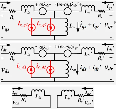
each phase branch. However, the stator magnetizing branches are modified by three virtual
resistors, Rc, which are highlighted in red in Fig. 10. Rc is in parallel with Lms in a similar manner
as in the per-phase equivalent circuit. However, the later derivation will show that Rc and rc_ph are
not the same. Due to the injection of Rc, the stator phase currents are split into two parts: one for
flux linkage generation via Lms and the other one for core loss dissipation via Rc. Note that the
rest of the stator circuit and the entire rotor circuit in Fig. 10 are the same as Fig. 9, which makes
the qd0-frame manipulation of the proposed model convenient by referring to the similar process as in the conventional dynamic three-phase model.
Fig. 10. The proposed IM model considering core loss
3.1.1 Derivation of the qd0-frame Forms of the Proposed Model and Loss Expressions
Taking phase a as an example, the phase voltage (vas), current (ias) and flux (λas) can be
calculated based on Fig. 10,
as s as as
v
R i
p
, (3.1) ˆ ms ˆ as as as c L i i pi R , (3.2)27
ˆ
0.5 ˆ 0.5 ˆ2 2
cos ' cos ' cos '
3 3 as ls as ms as ms bs ms cs ms r ar ms r br ms r cr L i L i L i L i L i L i L i , (3.3)
where p is the derivative operator, θr is the rotor electrical angle. The other variables in (3.1) to
(3.3) are illustrated in Fig. 10. Substituting ias in (3.3) using (3.2) leads to a flux expression in
terms of only magnetizing currents (ˆ
abcs
i ) and iabcr’. Note that the stator magnetizing currents
(the currents flowing through Lms) are changed from iabcs in Fig. 8 to iˆabcs in Fig. 10. Applying
the same analysis to phase b and phase c as well as to phases on the rotor side, it leads to the voltage, current and flux relationships of the three-phase system in matrix forms,
p
abcs s abcs abcs
abcr r abcr abcr
v R 0 i λ v ' 0 R ' i ' λ ' , (3.4) ˆ ˆ ms c L R
abcs abcs abcs
abcr abcr i i pi i ' i ' 0 , (3.5) ˆ ˆ ls ms c L L R
abcs ss sr abcs abcs
rs rr
abcr abcr
λ L L ' i pi
L ' L '
λ ' i ' 0 . (3.6)
Here, bold font represents matrix variables. Fabcx=[Fax Fbx Fcx]T, where F can represent voltage,
current or flux while the subscript x can be s or r to represent stator or rotor components, respectively. The superscript T means transpose of a matrix. The matrixes Rs, Rr’, Lss, Lsr’, Lrs’
and Lrr’ are 0 0 = 0 0 0 0 s s s R R R s R , (3.7)
28 ' 0 0 = 0 ' 0 0 0 ' r r r R R R r R ' , (3.8) 1 1 2 2 1 1 = 2 2 1 1 2 2 ls ms ms ms ms ls ms ms ms ms ls ms L L L L L L L L L L L L ss L , (3.9) 1 1 ' 2 2 1 1 = ' 2 2 1 1 ' 2 2 lr ms ms ms ms lr ms ms ms ms lr ms L L L L L L L L L L L L rr L ' , (3.10) 2 2
cos cos cos
3 3
2 2
cos cos cos
3 3
2 2
cos cos cos
3 3 r r r ms r r r r r r L sr rs L ' L ' . (3.11)
Transforming both sides of (3.4)–(3.6) into an arbitrary qd0-frame of frequency ω using the transformation matrix K, where Fqd0x=K·Fabcx and ˆiqd0s K iˆabcs, Fqd0x=[Fqx Fdx F0x]
T , ˆiqd0s=[ ˆiqs ˆ ds i iˆ0s]T, iˆabcs=[iˆas iˆbs iˆcs]T, and 2 2
cos cos cos
3 3
2 2 2
sin sin sin ,
3 3 3 1 1 1 2 2 2 d dt K . (3.12)
29
Then, the voltage, current and flux in the qd0-frame are obtained, which are referred as machine structural equations qs s qs ds qs