Givaki, Kamyab and Rahman, Md Habibur and VOZIKIS, Dimitrios and
Giveki, Ashkan (2018) Analysis of integration of multi-terminal HVDC
network to weak grids. In: 14th IET International Conference on AC and
DC Power Transmission, 2018-06-28 - 2018-06-29. ,
This version is available at
https://strathprints.strath.ac.uk/65493/
Strathprints is designed to allow users to access the research output of the University of Strathclyde. Unless otherwise explicitly stated on the manuscript, Copyright © and Moral Rights for the papers on this site are retained by the individual authors and/or other copyright owners. Please check the manuscript for details of any other licences that may have been applied. You may not engage in further distribution of the material for any profitmaking activities or any commercial gain. You may freely distribute both the url (https://strathprints.strath.ac.uk/) and the content of this paper for research or private study, educational, or not-for-profit purposes without prior permission or charge.
Any correspondence concerning this service should be sent to the Strathprints administrator: [email protected]
The Strathprints institutional repository (https://strathprints.strath.ac.uk) is a digital archive of University of Strathclyde research outputs. It has been developed to disseminate open access research outputs, expose data about those outputs, and enable the
1
ANALYSIS OF INTEGRATION OF
MULTI-TERMINAL HVDC NETWORK TO WEAK GRIDS
Kamyab Givaki
1*, Md Habibur Rahman
2, Dimitrios Vozikis
2, Ashkan Giveki
3,
1Edinburgh Napier University, Edinburgh, UK 2University of Strathclyde, Glasgow, UK
3Tehran University, Tehran, Iran
Keywords: MULTI-TERMINAL HVDC, VECTOR CURRENT CONTROL, WEAK GRID, DC VOLTAGE
CONTROL, VOLTAGE CONTROL, MODULAR MULTI-LEVEL CONVERTER.
Abstract
In this paper, the integration of multi-terminal HVDC systems to weak power grids is analysed under different grid strengths and control methods. In this paper, a modular multi-level converter based MTDC network is considered. The analysis showed the importance of voltage control of DC network. The voltage control of DC network needs to be performed from the converter station connected to the strongest AC network. Furthermore, the analysis shows that either droop or PI control can be used for controlling the DC voltage of the MTDC network connected to one or more weak grids. However, the droop control of DC voltage provides faster response compared to PI with larger steady state error. Finally, the analysis showed that the MMC-based MTDC is capable of ride-through unbalanced AC side faults even if the faults occur in a weak grid.
1
Introduction
Increased global energy demands and environmental concerns caused high integration of renewable energy generation to the power grids. Furthermore, energy exchange between neighbouring countries (markets) could be an option for meeting the increasing energy demands. Therefore, power needs to be transmitted over long distances and to ease the energy growth multi-terminal HVDC (MTDC) system is a favourable option for energy exchange.
On the other hands, large offshore wind farms have been planned in Europe and around the world. The integration of such offshore wind farms to the grid over long distance is one of the main challenges for the developers and system operators. Many of the UK’s proposed large offshore wind farms are located long distance away from the onshore connection points and MTDC becomes the preferred choice for their network integration[1]. The MTDC system is desired to capable of interfacing with all kinds of AC grid such as stiff, weak and passive grid system.
One of the main barriers for developing MTDC system is DC fault protection, fault location recognition and isolation [2-4]. A DC fault event in the MTDC network causes a steep rise in fault current and DC voltage collapse due to the low impedance of the system. Compare to two-level VSCs, half
bridge MMC is experienced lower DC fault current due to the absence of a large DC side capacitor at its converter terminal and the presence of relatively small cable capacitance [5]. Multi-terminal means more than two converter stations are interlinked by an HVDC transmission network. The most appropriate technology for multi-terminal applications is voltage source converters (VSC) based HVDC. In an MTDC system, the converter can act as either an inverter or a rectifier depending on its power direction. At least one VSC converter must be assigned to control the DC voltage link in order to maintain the power balance in the MTDC grid. No communication is required between the converters as VSC converter is governed by its local control and operates independently to provide fast multi-converter control of the MTDC system[6, 7]. On the other hand, to configure line commutated converter (LCC) based MTDC network is much more complicated where power flow direction is required to change. Therefore, DC voltage polarity needs to be adjusted for the power flow reversal but this could cause interruption to the entire MTDC network. Thus, large-scale offshore transmission grids integration in multi-terminal VSC HVDC becomes a preferable choice. Some researchers have also proposed hybrid MTDC transmission combined with both LCC and VSC technology [8, 9].
Examples of operational MTDC systems are Sardinia-Corsica-Italy interconnection, Quebec-New England interconnection, and Zhoushan DC Grid. First two projects are started as a point to point HVDC system and later extended to multi-terminal systems. However, Zhoushan DC Grid is a true MTDC system with 5 terminals [8, 10].
Furthermore, as the newly constructed or planned offshore wind farms are large injecting a bulk amount of power to the grid, and are located far from the conventional generation units, the strength of grid at the connection point is reduced dramatically [11, 12]. The strength of a point in the power system is measured by short circuit ratio (SCR). When the SCR is greater than 3 the system is considered as a strong grid and when 2<SCR<3 and SCR<2 the system is defined as weak and very weak, respectively [13].
A converter controlled by vector current controller connected to a weak power network can potentially become unstable, and
2
the active power transfer capability of the converter will be limited to a portion of converter rated power [14, 15]. For a weak grid, the voltage is very sensitive to both active and reactive power changes. Thus, voltage magnitude and phase angle stabilisation after a power change in a weak grid are required [16]. Therefore, for an MTDC system connected to multiple weak grids, the analysis of system requirement for a stable operation is important.
In this paper, a three-terminal MTDC system is considered to study the impacts of connecting MTDC system to different power grids with different strengths. Furthermore, different DC link voltage control methods are tested under various grid strength.
Following this introduction, the model of MTDC system, control methods, etc. are discussed in section 2. In section 3, case studies are discussed and simulation results are provided. The discussion of the simulation results and case studies are presented in section 4. Finally, section 5 concludes the paper.
2. Methodology
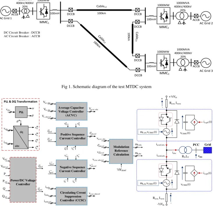
The layout of the test system is presented in Fig. 1. As shown in Fig. 1, a meshed MTDC network with three converter stations and 3 DC transmission cables are used for the analysis. The DC cables are modelled by the sections. Number of sections depends on the link length (each 10km is modelled as one section). The length of DC transmission cables in the MTDC network in all case studies and simulations are as shown in Fig. 1, unless said otherwise.
AC Grid 3 MMC3 1000MVA 400kV/400kV 20% 1GW MMC1 AC Grid 1 1000MW 1000MW AC Grid 2 1000MVA 400kV/400kV 20% MMC2 1000MW 400kV/400kV1000MVA 20% ACCB ACCB 100km 1 0 0 km C a b le 2 3 Cable12 ACCB DCCB 100mH 100mH 100mH DC Circuit Breaker : DCCB AC Circuit Breaker : ACCB
DCCB
DCCB
DCCB
DCCB
DCCB
Fig 1. Schematic diagram of the test MTDC system
PLL w q vabc iabc PLL & DQ Transformation abc dq vabc +_ vd +_ vq +_ id +_ iq +_ q + iqref + idref + iq + vd v+q Positive Sequence Current Controller + id + vabcref Vc-abcref Vuc-abc
Vlc-abc Average Capacitor Voltage Controller (ACVC) Vacvc-abc _ vabcref _ id _ iq _ vd _ vq Negative Sequence Current Controller _ iqref _ idref Circulating Crrent Suppression Controller (CCSC) vccsc-abcref iuabc ilabc izabcref P Pref Q Qref Power/DC Voltage Controller VDC VDCref i+dref + iqref Modulation Reference Calculation mLabc mUabc ½Vdcref vacvc-abc + vabcref _ vabcref vccsc-abcref + ½Vdc Rarm, Larm + -icapU(t) vCSMU(t) RT,LT iabc icapL(t) vCSML(t) Rarm, Larm + -+ -iarmLabc + -mUabcvCSMU(t) iarmUab c PCC vabc Grid -½Vdc mLabcvCSMU(t)
3
It is assumed that MMC3 controls the DC network voltage.
Two different DC voltage control strategies are used and compared, droop control and proportional-integral (PI) control of DC grid voltage. The other converter stations (MMC1 and
MMC2) are also controlling the active power flow to/from the
DC network. For these converters, the power orders are set and the d- axis current reference is calculated as (1)
(1) where P*is the power order, and and represent the
d-axis voltage of converter terminal and current reference, respectively.
In this paper, the average model of the half-bridge MMC is used to offer faster simulation times than the switched model. The average model swaps the string of cells in each arm with a single average value cell. The capacitances of all cells (within an arm) are aggregated and modelled as a single capacitance which is fed by a current source which replicates current within the voltage source. The voltage built up across the arm is defined by the number of cells that are switched on within an arm and is modelled as a controllable voltage source, the magnitude of which is given by the modulation index m used to measure the cell capacitor voltage[17].
The values of parameters used in simulations are presented in Table.1 and Table 2. Furthermore, Table .3 presents the cable parameters.
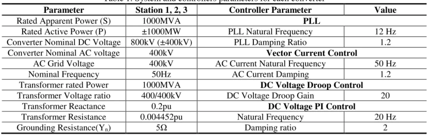
Fig. 2 shows the control block diagram and average model of the MMC station. As seen Fig. 2, the current controller consists
of positive and negative sequences. The AC voltage/reactive power and DC voltage/reactive power are regulated through direct and quadrature orders of the positive current orders, respectively. On the other hands, the references for negative sequence d- and q-axis currents are set at zero, to eliminate negative sequence currents during asymmetric ac faults or unbalanced voltage. By using positive and negative sequence controllers, the contribution of MMC to AC faults is limited and the main AC modulating signals are generated.
Furthermore, an active circulating current suppression controller (CCSC) is utilised in the model (Fig. 2) to limit the 2nd order harmonic of the MMC arm current. This will reduce
power losses of switches and voltage ripples of the capacitor voltage of sub-modules. The output of this controller is applied to the modulating signal.
Another supplementary controller (average capacitor voltage controller) is used in Fig. 2 to improve the dynamic responses of MMC. The output of this controller is added to the main modulation signals and mainly adjusts the DC component of modulation signals. The ACVC independently regulates the voltages of half-bridge sub-modules capacitors. In case of any changes in the active power/DC voltage orders, this controller eliminates the requirement of a significant change in the energy level of cell capacitors.
In all the simulations, SCR is defined by the short circuit capacity at the AC side connection point and XRr (the ratio of inductive part to the resistive part of the grid impedance) is set to 7.
.
Table 1. System and controllers parameters for each converter
Parameter Station 1, 2, 3 Controller Parameter Value
Rated Apparent Power (S) 1000MVA PLL
Rated Active Power (P) ±1000MW PLL Natural Frequency 12 Hz
Converter Nominal DC Voltage 800kV (±400kV) PLL Damping Ratio 1.2
Converter Nominal AC voltage 400kV Vector Current Control
AC Grid Voltage 400kV AC Current Natural Frequency 50 Hz
Nominal Frequency 50Hz AC Current Damping 1.2
Transformer rated Power 1000MVA DC Voltage Droop Control
Transformer Voltage ratio 400/400kV DC Voltage Droop Gain 20
Transformer Reactance 0.2pu DC Voltage PI Control
Transformer Resistance 0.004452pu Natural Frequency 20 Hz
Grounding Resistance(Yn) 5 Damping ratio 2
Table 2. Internal parameters of MMC for simulation
Parameter Value
Arm inductance 10%
Number of cells per arm (N) 400
Cell Capacitance 9.4mF
Average Cell capacitance 24.7 F IGBT/Diode Snubber Resistance 50Ω IGBT/Diode Snubber Capacitance 25nF
DC Link Inductance(DCL) 100mH Table 3. DC cable parameters
Cable Parameter V
alue
Resistance 0.009 /km Inductance 1.4mH/km Capacitance 0.23µF/km
4
3
Case Studies
In this section, different cases are considered to study the behaviour of an MTDC system connected to weak power networks and simulation have been conducted in Matlab/Simulink platform.
3.1 Strong grids, different DC voltage control
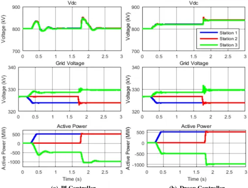
For this case, it is assumed that the SCR at the connection point of AC networks to the MTDC system is 5. In this section, droop control and PI control of DC voltage are compared. The power of station 1 and station 2 ramped up to +500MW (rectifying) at 0.25s and 1.75s, respectively. Therefore, the power of station 3 is then increased to -1000MW (inverting). As seen in Fig. 3, the DC voltage, one phase RMS AC voltage and active power of 3 converter stations are well controlled with both control methods.
As seen in Fig. 3, the DC voltage overshoot and settling time with PI is larger compared to droop controller, however, using droop controller will cause around 5% steady-state error when station 3 (converter that controls the DC voltage) transfers the rated power.
The inverting and rectifying operation modes of station
1 and 2 and station 3 with DC voltage droop control are
presented in Figs. 4 (a) and (b), respectively.
3.2 Weak AC grids at different positions
In this section, various grid strengths are tested for each AC grid connected to converter stations.
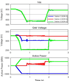
Firstly, the SCR of AC grids 1 and 3 are considered to be 2 (weak grids), and AC grid 2 is assumed to be a strong one (SCR=5). As the previous case, converter 3 controls the DC voltage of MTDC network using droop control. The simulation results for this case is presented in Fig. 5.
The operation of the converter as a rectifier, when connected to the weak grid, is more likely to become unstable [18] compared to inverter operation mode. Therefore, in this case, the active power output of station 1 is ramped to -1000MW (inverting) at 0.25s and the power order of station 2 is 0 (before 1.75s), station 3 needs to work as a rectifier. Therefore, this case will be a very difficult case for station 3 to deal with.
(b). Droop Controller (a). PI Controller
Fig. 3. Different DC link voltage controller (strong AC grids)
(a). Inversion (b). Rectification
Time(s) Time(s)
5
Station 1 (SCR=2) Station 2 (SCR=5) Station 3 (SCR=2)
Fig. 5. Stations 1 and 3 are connected to a weak AC grid, Station 2 connected to a strong AC grid
Station 1 (SCR=2) Station 2 (SCR=2) Station 3 (SCR=5)
Fig. 6. Stations 1 and 2 are connected to a weak AC grid, Station 3 connected to a strong AC grid
As seen in Fig. 5, the DC voltage of MTDC network is dramatically decreased to 565kV (29.3% voltage drop) at t=0.8s. As seen in Fig. 5, despite the power order of station 2 which is set 0, the active power of station 2 starts to increase at t=0.8s and then the power starts to oscillate. This phenomenon happens even when the MTDC network voltage is controlled with PI controller. For a stable operation of the system and power flow control, the DC voltage needs to be maintained and controlled at a constant level. However, when the DC voltage control is performed by the converter connected to the weak grid, the DC voltage cannot be maintained due to the power flow constraint to a weak grid. Finally, at 1.75s, when the power of station 2 ramped to 500MW, the total power of station 3 reduces to 500 MW that
does not violate the power flow constraints of station 3 and the system comes back to stable operation and DC voltage again increase to around its rated value (800kV).
Conversely, in Fig. 6, station 3 which controls MTDC voltage is connected to a strong AC grid with SCR=5. As seen in Fig. 6, the power of station 1 ramped to -1000 MW (Inverting). However, in this case, two other stations are connected to weak AC grids, all the stations follow the power orders as mentioned in previous case and the system is stable.
From the simulation results presented in Figs. 5 and 6, it can be concluded that for stable operation of an MMC-based MTDC controlled by vector current control, one of the AC grids connected to converter station need to be strong one and that the DC voltage control of MTDC should be performed from the converter station connected to that strong grid. Therefore, in rest of simulation in this paper. It is assumed that the DC voltage control is performed by the converter station connected to strong grid and the rest of stations are connected to weak AC network.
3.3 Comparison of capability of power transfer capability with different DC voltage controller and operation mode
In this section, the power transfer capability of converters connected to weak grids with different controllers and operating modes are compared. The SCRs of AC grids 1 and 2 are set to 1 (very weak grid). The SCR of AC grid 3 is set to 5 (strong) so that the DC voltage of MTDC network maintain constant and it does not compromise the results of active power transfer capability for other converters. It is assumed that the length of cable13 is also 100km similar to other cables
lengths.
It is assumed that the station 1 works as inverter and station 2 works as a rectifier. The results for power transfer capability of stations are presented in Table. 4. As the AC grid 3 is strong, the power transfer capability of station 3 is not presented in Table 4.
As seen Table 4, the power capability of the converter with both PI and droop control of DC voltage is similar. However, in rectifying mode (+ sign power) the transfer capability is lower compared to inverting mode (- sign power).
It should be noted that in the relevant literature, it is reported that converter connected to the weak grid can transfer up to 60-70% of the rated power[14], however, to achieve this number, comprehensive control tuning effort is needed which is out of the scope of this paper.
Table 4. Power transfer capability
Mode of Operation Controller
Station 1 Station 2
PI -575 MW +416 MW
6
3.4 Unbalanced fault at weak AC network
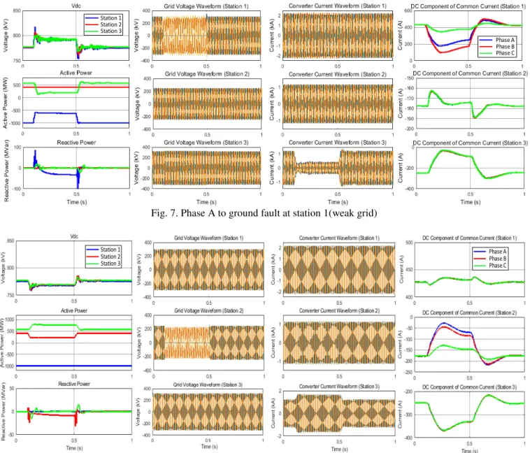
In this section, the MTDC connected to the weak grid is tested. For the simulations in this section, the SCRs of AC grids 1, 2, and 3 are 2, 1, and 5, respectively. Furthermore, station 1ans station 2 power orders are -1000MW and 500MW from 0s, respectively, and Station 3 controls the DC voltage. However, the power order of station 2 is set to 500MW, the real output of station 2 is curtailed to the around 420MW due to the very weak grid connection (SCR=1) of station 2.
In Fig. 7, a low impedance (0.001 ) single phase fault (phase A) to the ground is applied to the connection point of the station 1 to AC grid 1 (weak grid) at 0.1 s for 0.4 s. The voltage of phase A of the station 1 drops to 0 after fault occurrence. As seen in Fig. 7, when the fault happens the DC component of common current of different legs of MMC in station 1 are deviating from each other and after fault clearance, overlay very fast, which means that the converter is capable of
ride-through the unbalanced AC fault even if the AC fault happens in the connection point to weak AC grid. As it is seen in Fig. 7, during the fault, the converter is able to transfer the active power, however the power is reduced due to the unbalanced operation of converter (during unbalanced fault). Furthermore, the reactive power that is required for the AC voltage support is limited to 100MVar. The voltage of other stations are not impacted by the fault and DC voltage is well controlled.
Furthermore, in Fig. 8, the operational points and parameters of the system before the fault occurrence are similar to those for Fig. 7. In Fig. 8 a single phase to ground fault with the same duration and fault impedance occurs at the connection point of station 2 to AC grid 2 which is a very weak grid (SCR=1). Similar to the previous case the system is capable of riding-through the fault even with a very weak AC grid.
Station 1 Station 2 Station 3 Phase A Phase B Phase C
Fig. 7. Phase A to ground fault at station 1(weak grid)
Station 1 Station 2 Station 3 Phase A Phase B Phase C
7
4
Discussion and Conclusions
In this paper, a three terminal MMC based MTDC system connected to weak grids is studied. The study has shown that control of MTDC voltage is very important to ensure the stable operation of the system. Control of DC voltage of MTDC network should be performed from the MMC station connected to the strongest AC system. The simulation results have also shown that the MTDC system connected to the weak and very weak grid, can ride-through the unbalanced fault as long as the power transfer limits of the system are considered.
5
Acknowledgements
This work is supported in part by the EPSRC, project reference numbers EP/G037728/1S.
6
References
[1] L. Xu, L. Yao, and M. Bazargan, "DC grid management of a
multi-terminal HVDC transmission system for large offshore
wind farms," in Sustainable Power Generation and Supply,
2009. SUPERGEN '09. International Conference on, 2009, pp.
1-7.
[2] Y. Gao, M. Bazargan, L. Xu, and W. Liang, "DC fault analysis of
MMC based HVDC system for large offshore wind farm
integration," in Renewable Power Generation Conference (RPG
2013), 2nd IET, 2013, pp. 1-4.
[3] R. Li, L. Xu, and L. Yao, "DC fault detection and location in meshed multi-terminal HVDC systems based on DC reactor
voltage change rate," IEEE Transactions on Power Delivery, 7/9
2016.
[4] L. Tang and B.-T. Ooi, "Locating and Isolating DC Faults in
Multi-Terminal DC Systems," IEEE Trans. on Power Delivery, vol. 22,
pp. 1877-1884, 2007.
[5] M. H. Rahman, L. Xu, and L. Yao, "Protection of large
partitioned MTDC Networks Using DC-DC converters and
circuit breakers," Protection and Control of Modern Power
Systems, vol. 1, p. 19, 2016.
[6] T. M. Haileselassie, "Control of Multi-terminal VSC-HVDC
Systems," MSc, Electrical Power Engineering, Norwegian University of Science and Technology, 2012.
[7] L. Tang, "Control and Application of Multi-terminal HVDC
based on voltage-Source Converter," Doctor of Philosophy, Electrical and Computer Engineering, McGill University, Montréal, Québec, Canada, 2003.
[8] L. L. Wang Hao, and Wu Dianfeng. (2014, 27/02/2015).
'Hierarchical control in a 5-terminal VSC-HVDC project'.
Available:
http://www.ee.co.za/article/hierarchical-control-5-terminal-vsc-hvdc-project.html
[9] M. H. Rahman, L. Xu, and L. Yao, "DC fault protection strategy
considering DC network partition," in Power and Energy
Society General Meeting (PESGM), 2016, 2016, pp. 1-5.
[10] T. An, G. Tang, and W. Wang, "Research and application on multi-terminal and DC grids based on VSC-HVDC technology in
China," High Voltage, vol. 2, pp. 1-10, 2017.
[11] K. Givaki, D. Chen, and O. Anaya-Lara, "Stability studies of different AC collection network topologies in wind farms," presented at the International Conference on Renewable Power Generation, London, 2016.
[12] K. Givaki and L. Xu, "Stability analysis of large wind farms connected to weak AC networks incorporating PLL dynamics,"
in International Conference on Renewable Power Generation
2015, pp. 1-6.
[13] "IEEE Guide for Planning DC Links Terminating at AC Locations Having Low Short-Circuit Capacities," IEEE Power & Energy Society1997.
[14] A. Egea-Alvarez, S. Fekriasl, F. Hassan, and O. Gomis-Bellmunt, "Advanced Vector Control for Voltage Source Converters
Connected to Weak Grids," IEEE Trans. Power Syst., vol. 30, pp.
3072-3081, 2015.
[15] L. Zhang, L. Harnefors, and H. P. Nee, "Power-Synchronization
Control of Grid-Connected Voltage-Source Converters," IEEE
Trans. Power Syst., vol. 25, pp. 809-820, 2010.
[16] "Connection of Wind Farms to Weak AC Networks," cigre2016. [17] J. Peralta, H. Saad, S. Dennetiere, J. Mahseredjian, and S. Nguefeu, "Detailed and Averaged Models for a 401-Level
MMCHVDC System," IEEE Trans. Power Deli., vol. 27, pp.
1501-1508, 2012.
[18] B. Yuan, J. Xu, C. Zhao, and Y. Yuan, "An Improved Phase-Locked-Loop Control with Alternative Damping Factors for VSC
Connected to Weak AC System," J. Control Sci. Eng., vol. 2016,