TECHNISCHE UNIVERSITÄT DRESDEN
Analysis of Bandwidth and Latency
Constraints on a Packetized
Cloud Radio Access Network Fronthaul
Jay Kant Chaudhary
der Fakultät Elektrotechnik und Informationstechnik der Technischen Universität Dresden
zur Erlangung des akademischen Grades eines
Doktoringenieurs
(Dr.-Ing.)
genehmigte Dissertation
Vorsitzender: Prof. Dr.-Ing. habil. Christian Georg Mayr Gutachter: Prof. Dr.-Ing. Dr. h.c. Gerhard Fettweis
Prof. Dr. Steinar Bjørnstad Tag der Einreichung: 29. Oktober 2019
Jay Kant Chaudhary
Analysis of Bandwidth and Latency Constraints on a Packetized Cloud Radio Access Network Fronthaul
Dissertation, 26. Februar 2020
Vodafone Chair Mobile Communications Systems Institut für Nachrichtentechnik
Fakultät Elektrotechnik und Informationstechnik Technische Universität Dresden
Abstract
Cloud radio access network (C-RAN) is a promising architecture for the next-generation RAN to meet the diverse and stringent requirements envisioned by fifth generation mo-bile communication systems (5G) and future generation momo-bile networks. C-RAN offers several advantages, such as reduced capital expenditure (CAPEX) and operational expen-diture (OPEX), increased spectral efficiency (SE), higher capacity and improved cell-edge performance, and efficient hardware utilization through resource sharing and network function virtualization (NFV). However, these centralization gains come with the need for a fronthaul, which is the transport link connecting remote radio units (RRUs) to the base band unit (BBU) pool. In conventional C-RAN, legacy common public radio inter-face (CPRI) protocol is used on the fronthaul network to transport the raw, unprocessed baseband in-phase/quadrature-phase (I/Q) samples between the BBU and the RRUs, and it demands a huge fronthaul bandwidth, a strict low-latency, in the order of a few hundred microseconds, and a very high reliability.
Hence, in order to relax the excessive fronthaul bandwidth and stringent low-latency requirements, as well as to enhance the flexibility of the fronthaul, it is utmost important to redesign the fronthaul, while still profiting from the acclaimed centralization benefits. Therefore, a flexibly centralized C-RAN with different functional splits has been intro-duced. In addition, 5G mobile fronthaul (often also termed as an evolved fronthaul) is envisioned to be packet-based, utilizing the Ethernet as a transport technology.
In this thesis, to circumvent the fronthaul bandwidth constraint, a packetized fronthaul considering an appropriate functional split such that the fronthaul data rate is coupled with actual user data rate, unlike the classical C-RAN where fronthaul data rate is always
static and independent of the traffic load, is justifiably chosen. We adapt queuing and spatial traffic models to derive the mathematical expressions for statistical multiplexing gains that can be obtained from the randomness in the user traffic. Through this, we show that the required fronthaul bandwidth can be reduced significantly, depending on the overall traffic demand, correlation distance and outage probability. Furthermore, an iterative optimization algorithm is developed, showing the impacts of number of pilots on a bandwidth-constrained fronthaul. This algorithm achieves additional reduction in the required fronthaul bandwidth.
Next, knowing the multiplexing gains and possible fronthaul bandwidth reduction, it is beneficial for the mobile network operators (MNOs) to deploy the optical transceiver (TRX) modules in C-RAN cost efficiently. For this, using the same framework, a cost model for fronthaul TRX cost optimization is presented. This is essential in C-RAN, be-cause in a wavelength division multiplexing-passive optical network (WDM-PON) system, TRXs are generally deployed to serve at a peak load. But, because of variations in the traffic demands, owing to tidal effect, the fronthaul can be dimensioned requiring a lower capacity allowing a reasonable outage, thus giving rise to cost saving by deploying fewer TRXs, and energy saving by putting the unused TRXs in sleep mode.
iv
The second focus of the thesis is the fronthaul latency analysis, which is a critical per-formance metric, especially for ultra-reliable and low latency communication (URLLC). An analytical framework to calculate the latency in the uplink (UL) of C-RAN massive multiple-input multiple-output (MIMO) system is presented. For this, a continuous-time queuing model for the Ethernet switch in the fronthaul network, which aggregates the UL traffic from several massive MIMO-aided RRUs, is considered. The closed-form solutions for the moment generating function (MGF) of sojourn time, waiting time and queue length distributions are derived using Pollaczek–Khinchine formula for our M/HE/1 queuing model, and evaluated via numerical solutions. In addition, the packet loss rate – due to the inability of the packets to reach the destination in a certain time – is derived. Due to the slotted nature of the UL transmissions, the model is extended to a discrete-time queuing model. The impact of the packet arrival rate, average packet size, SE of users, and fronthaul capacity on the sojourn time, waiting time and queue length distributions are analyzed.
While offloading more signal processing functionalities to the RRU reduces the required fronthaul bandwidth considerably, this increases the complexity at the RRU. Hence, con-sidering the 5G New Radio (NR) flexible numerology and XRAN functional split with a detailed radio frequency (RF) chain at the RRU, the total RRU complexity is computed first, and later, a tradeoff between the required fronthaul bandwidth and RRU complexity is analyzed.
We conclude that despite the numerous C-RAN benefits, the stringent fronthaul band-width and latency constraints must be carefully evaluated, and an optimal functional split is essential to meet diverse set of requirements imposed by new radio access technologies (RATs).
Kurzfassung
Ein cloud-basiertes Mobilfunkzugangsnetz (cloud radio access network, C-RAN) stellt eine vielversprechende Architektur für das RAN der nächsten Generation dar, um die vielfältigen und strengen Anforderungen der fünften (5G) und zukünftigen Generatio-nen von Mobilfunknetzen zu erfüllen. C-RAN bietet mehrere Vorteile, wie z.B. reduzierte Investitions- (CAPEX) und Betriebskosten (OPEX), erhöhte spektrale Effizienz (SE), höhere Kapazität und verbesserte Leistung am Zellrand sowie effiziente Hardwareaus-lastung durch Ressourcenteilung und Virtualisierung von Netzwerkfunktionen (network function virtualization, NFV). Diese Zentralisierungsvorteile erfordern jedoch eine Trans-portverbindung (Fronthaul), die die Antenneneinheiten (remote radio units, RRUs) mit dem Pool an Basisbandeinheiten (basisband unit, BBU) verbindet. Im konventionellen C-RAN wird das bestehende CPRI-Protokoll (common public radio interface) für das Fronthaul-Netzwerk verwendet, um die rohen, unverarbeiteten Abtastwerte der In-Phase-und Quadraturkomponente (I/Q) des Basisbands zwischen der BBU In-Phase-und den RRUs zu transportieren. Dies erfordert eine enorme Fronthaul-Bandbreite, eine strenge niedrige Latenz in der Größenordnung von einigen hundert Mikrosekunden und eine sehr hohe Zuverlässigkeit.
Um die extrem große Fronthaul-Bandbreite und die strengen Anforderungen an die geringe Latenz zu lockern und die Flexibilität des Fronthauls zu erhöhen, ist es daher äußerst wichtig, das Fronthaul neu zu gestalten und dabei trotzdem von den erwarteten Vorteilen der Zentralisierung zu profitieren. Daher wurde ein flexibel zentralisiertes C-RAN mit unterschiedlichen Funktionsaufteilungen eingeführt. Außerdem ist das mobile 5G-Fronthaul (oft auch als evolved Fronthaul bezeichnet) als paketbasiert konzipiert und nutzt Ethernet als Transporttechnologie.
Um die Bandbreitenbeschränkung zu erfüllen, wird in dieser Arbeit ein paketbasiertes Fronthaul unter Berücksichtigung einer geeigneten funktionalen Aufteilung so gewählt, dass die Fronthaul-Datenrate mit der tatsächlichen Nutzdatenrate gekoppelt wird, im Gegensatz zum klassischen C-RAN, bei dem die Fronthaul-Datenrate immer statisch
und unabhängig von der Verkehrsbelastung ist. Wir passen Warteschlangen- und räum-liche Verkehrsmodelle an, um mathematische Ausdrücke für statistische Multiplexing-Gewinne herzuleiten, die aus der Zufälligkeit im Benutzerverkehr gewonnen werden kön-nen. Hierdurch zeigen wir, dass die erforderliche Fronthaul-Bandbreite abhängig von der Gesamtverkehrsnachfrage, der Korrelationsdistanz und der Ausfallwahrscheinlichkeit deutlich reduziert werden kann. Darüber hinaus wird ein iterativer Optimierungsalgo-rithmus entwickelt, der die Auswirkungen der Anzahl der Piloten auf das bandbreit-enbeschränkte Fronthaul zeigt. Dieser Algorithmus erreicht eine zusätzliche Reduktion der benötigte Fronthaul-Bandbreite.
Mit dem Wissen über die Multiplexing-Gewinne und die mögliche Reduktion der Fronthaul-Bandbreite ist es für die Mobilfunkbetreiber (mobile network operators, MNOs) von Vorteil, die Module des optischen Sendeempfängers (transceiver, TRX)
vi
stig im C-RAN einzusetzen. Dazu wird unter Verwendung des gleichen Rahmenwerks ein Kostenmodell zur Fronthaul-TRX-Kostenoptimierung vorgestellt. Dies ist im C-RAN unerlässlich, da in einem WDM-PON-System (wavelength division multiplexing-passive optical network) die TRX im Allgemeinen bei Spitzenlast eingesetzt werden. Aufgrund der Schwankungen in den Verkehrsanforderungen (Gezeiteneffekt) kann das Fronthaul je-doch mit einer geringeren Kapazität dimensioniert werden, die einen vertretbaren Ausfall in Kauf nimmt, was zu Kosteneinsparungen durch den Einsatz von weniger TRXn und Energieeinsparungen durch den Einsatz der ungenutzten TRX im Schlafmodus führt.
Der zweite Schwerpunkt der Arbeit ist die Fronthaul-Latenzanalyse, die eine kritis-che Leistungskennzahl liefert, insbesondere für die hochzuverlässige und niedriglatente Kommunikation (ultra-reliable low latency communications, URLLC). Ein analytisches Modell zur Berechnung der Latenz im Uplink (UL) des C-RAN mit massivem MIMO (multiple input multiple output) wird vorgestellt. Dazu wird ein Warteschlangen-Modell mit kontinuierlicher Zeit für den Ethernet-Switch im Fronthaul-Netzwerk betrachtet, das den UL-Verkehr von mehreren RRUs mit massivem MIMO aggregiert. Die geschlossenen Lösungen für die momenterzeugende Funktion (moment generating function, MGF) von Verweildauer-, Wartezeit- und Warteschlangenlängenverteilungen werden mit Hilfe der Pollaczek-Khinchin-Formel für unser M/HE/1-Warteschlangenmodell hergeleitet und mittels numerischer Verfahren ausgewertet. Darüber hinaus wird die Paketverlustrate derjenigen Pakete, die das Ziel nicht in einer bestimmten Zeit erreichen, hergeleitet. Auf-grund der Organisation der UL-Übertragungen in Zeitschlitzen wird das Modell zu einem Warteschlangenmodell mit diskreter Zeit erweitert. Der Einfluss der Paketankunftsrate, der durchschnittlichen Paketgröße, der SE der Benutzer und der Fronthaul-Kapazität auf die Verweildauer-, die Wartezeit- und die Warteschlangenlängenverteilung wird analysiert. Während das Verlagern weiterer Signalverarbeitungsfunktionalitäten an die RRU die erforderliche Fronthaul-Bandbreite erheblich reduziert, erhöht sich dadurch im Gegenzug die Komplexität der RRU. Daher wird unter Berücksichtigung der flexiblen Numerologie von 5G New Radio (NR) und der XRAN-Funktionenaufteilung mit einer detaillierten RF-Kette (radio frequency) am RRU zunächst die gesamte RRU-Komplexität berechnet und später ein Kompromiss zwischen der erforderlichen Fronthaul-Bandbreite und der RRU-Komplexität untersucht.
Wir kommen zu dem Schluss, dass trotz der zahlreichen Vorteile von C-RAN die strengen Bandbreiten- und Latenzbedingungen an das Fronthaul sorgfältig geprüft wer-den müssen und eine optimale funktionale Aufteilung unerlässlich ist, um die vielfältigen Anforderungen der neuen Funkzugangstechnologien (radio access technologies, RATs) zu erfüllen.
Acknowledgement
This thesis is the result of continued effort of four years of a long journey at the Vodafone Chair Mobile Communication Systems at the TU Dresden. This journey seemed to me like a roller-coaster ride with many joys and a few hurdles in between. Despite me being the actor, I would like to take this opportunity to thank all the directors of this research work, who played quite an influential role, directly and indirectly.
First and foremost, I would like to express my deepest gratitude to my doctoral su-pervisor Prof. Gerhard Fettweis for having trust in my potential for this research, for providing his continuous support over the last years, and concrete guidelines and advices during my study and work at the Vodafone Chair Mobile Communication Systems at the TU Dresden. Particularly, I am overwhelmed by his capability of providing construc-tive ideas and immediate approaches towards problem solution, and not to forget, by his friendly and motivational behaviour.
Further, I would like to thank Prof. Steinar Bjørnstad, the second referee, for his time to review my thesis and providing valuable feedback and suggestion.
I am also grateful to my current group leader Dr. André Noll Barreto and former group leaders Dr. Dan Zhang and Dr. Meryem Simsek. Their willingness to help, detailed insights during numerous meetings, doksems and whiteboad brainstorming sessions pro-vided fruitful outcomes, which paved a way in right direction for the completeness of this thesis.
A special thanks goes to my colleagues at the chair, most importantly Dr. Jobin Francis and Dr. Jens Bartelt for their productive collaboration as well fruitful discussions. Not to forget, in a non-exhaustive list, I would also like to thank other colleagues at the chair: Ahmad, Atul, Behnam, David, Henrik, Lucas, Max, Philipp, Tom, and Waqar. With many of them, I often had business travel, free time, and numerous technical and non-technical discussions. I owe you all guys tons of thanks.
During my PhD work, I had the pleasure of working with the EU projects: 5G-XHaul and 5G-PICTURE, and my research topic was mostly aligned with their objectives. I would like to thank all the involved project members, particularly Eckhard Grass, Jesús Gutiérrez and Jim Zou.
In addition, here at the chair many administrative tasks, especially applying for travel and reimbursements, contract extension, etc. would have been a big mess and troublesome without the continued support from Kathrin Fromke, Sylvia Steppat and Eva Bolza-Schünemann. Furthermore, I have received much help and support from our IT specialists: Raffael Kozerski and Rüdiger Hartmann. Hence, my heart cannot refrain me from offering them big thanks for their support.
My studies would not have been possible without the financial and moral support vii
viii
of my parents, since the time eight years ago when I moved to Finland for my master study, and later to Germany for a PhD. Especially, my father’s desire that his son should have a doctoral degree always gave me a motivational and inspirational boost. I am truly indebted to them. Last but quite importantly, I am thankful to my wife Pinki, a.k.a., my better half, for her unconditional love, and unquestionable support and care. I still recall her motivation and encouragement, especially at the time when I was having many ups and downs. I am hopeful to have such a great journey ahead together with our little angel, Aayara. Dear wife, let me beside by you forever.
Contents
Abstract iii Kurzfassung v Acknowledgement vii 1 Introduction 1 1.1 Motivation . . . 11.2 Contributions and Thesis Outline . . . 3
2 Radio Access Network Architecture 7 2.1 Cloud Radio Access Network Architectures . . . 8
2.1.1 Radio Access Network Architecture Overview: From D-RAN to C-RAN . . . 8
2.1.2 Flexible RAN Architecture: Birth of Functional Split . . . 13
2.2 Packet-based Fronthaul Networks . . . 19
2.2.1 Standardisation Activities . . . 19
2.2.2 Challenges in Ethernet Fronthaul Network . . . 20
2.2.3 Ethernet Switch Structure . . . 20
2.3 Queuing System . . . 21
2.4 Chapter Summary . . . 24
3 Bandwidth-Constrained C-RAN Fronthaul 25 3.1 Packet-switched C-RAN Fronthaul . . . 26
3.2 Statistical Multiplexing Motivation . . . 27
3.3 System model . . . 28
3.3.1 MIMO Rate . . . 28
3.3.2 Queueing model . . . 30
3.3.3 Fronthaul Capacity, Outage and Multiplexing . . . 32
3.3.4 Traffic Model . . . 33
3.4 Pilot-based Optimization . . . 34
3.5 Numerical Results . . . 36
3.5.1 Statistical Multiplexing Gains . . . 36
3.5.2 Pilot Optimization . . . 38
3.6 Transceiver Cost Saving Analysis . . . 40 ix
x Contents
3.6.1 WDM-PON System . . . 40
3.6.2 Transceiver Cost Saving Model . . . 41
3.6.3 Results . . . 43
3.7 Chapter Summary . . . 45
4 Latency-Constrained C-RAN Fronthaul with Continuous-Time Queuing Model 47 4.1 System Model . . . 49
4.1.1 Massive MIMO Access Network . . . 50
4.1.2 User Traffic Model and Ethernet-based Fronthaul Network . . . 52
4.2 Queuing Theoretic Modeling and Steady-state Analysis . . . 52
4.2.1 Queue Model . . . 52
4.2.2 Steady-state Analysis . . . 54
4.2.3 Extension to General File Size Distribution . . . 56
4.2.4 Packet Loss Rate . . . 57
4.3 Numerical Results . . . 57
4.3.1 Access Link Throughput . . . 57
4.3.2 Sojourn Time and Queue Length . . . 58
4.3.3 Packet Size Impact . . . 60
4.3.4 Waiting Time . . . 61
4.3.5 Packet Loss Rate . . . 62
4.4 Chapter Summary . . . 63
5 Latency-Constrained C-RAN Fronthaul with Discrete-Time Queuing Model 65 5.1 System Model . . . 65
5.2 Queue Modeling and Steady-state Analysis . . . 68
5.2.1 Queue Model . . . 68
5.2.2 Steady-state Analysis . . . 69
5.3 Numerical Results . . . 71
5.4 Chapter Summary . . . 73
6 RRU Computational Complexity Analysis in C-RAN 75 6.1 Introduction and Motivation . . . 75
6.2 Flexible 5G New Radio . . . 76
6.3 C-RAN Complexity Analysis . . . 78
6.4 Results . . . 80
6.5 Chapter Summary . . . 85
7 Conclusion and Outlook 87 7.1 Core Findings and Summary . . . 87
Contents xi
A Appendix 91
A.1 Derivation of Ki for exponentially distributed file size . . . 91
A.2 Derivation of Ki for gamma distributed file size . . . 92
A.3 Derivation of ΨS(s)for gamma distributed file size . . . 93
A.4 Derivation of FB(x) . . . 93 List of Abbreviations 95 List of Symbols 101 List of Figures 105 List of Tables 109 Bibliography 111
Publications of the Author 121
Chapter 1
Introduction
1.1
Motivation
Since the introduction of the first generation mobile communication systems (1G) in 1980’s, cellular mobile communications have witnessed a phenomenal growth over the re-cent decades. While 1G was analog only, the second generation mobile communication systems (2G) extended its capability to digital with voice, short message service (SMS) and very limited data services. With the introduction of the third generation mobile com-munication systems (3G) and fourth generation mobile comcom-munication systems (4G), the circuit-switched network in 2G was shifted towards packet-switched network providing massive mobile broadband, ubiquitous connectivity and on-demand video streaming, to name a few. Ever increasing continued demand of mobile broadband services is surging, requiring yet another generation of mobile technology to address the emerging challenges. The current Cisco Visual Networking Index (VNI) forecasts in [Cis19] that the overall mo-bile data traffic will grow to 77.5 exabytes per month by 2022, showing nearly a threefold increase compared with that in 2019.
As the quest for quality of service (QoS) and quality of experience (QoE) is contin-uously evolving, standardization bodies and industry forums, such as the next genera-tion mobile network (NGMN) [NGM15b], third generagenera-tion partnership project (3GPP) [3GP17a] and fifth generation public private partnership (5GPPP) [5GP19] have started working on the next-generation mobile technology (5G), which is considered to be both evolutionary and revolutionary1 from the state-of-the-art (SoTA) 4G technologies. 5G
aims to provide not only massive capacity and massive connectivity needed for a new era of communication for enhanced mobile broadband (eMBB) but also new use cases and applications: massive machine-type communication (mMTC), and ultra-reliable and low latency communication (URLLC). While eMBB focuses mainly on providing a very high peak data rate, better spectral and energy efficiency, improved performance and increased seamless user experience, mMTC aims to support a very large number of connected devices that require relatively a lower bit rate but a better network energy efficiency, since longer battery life is vital for such devices (e.g., actuators, sensors). URLLC focuses on provid-1Although 5G was initially hyped to be a revolutionary technology (refer to e.g., [Deu]) from the 4G technology, there are also some disagreements on this claim (refer to e.g., [Nok]).
2 1 Introduction ing highly reliable and low-latency communications for mission-critical applications, such as wireless industry automation, tactile internet, medical applications (e.g., telesurgery), augmented reality (AR), virtual reality (VR), smart grid and intelligent transport sys-tems (ITSs). Thus, it is quite probable that 5G will offer a true potential to enable the connection of everyone to everything, transforming our digital lives and means of com-munication [Nok].
While the mobile internet traffic is continuously increasing, due to unprecedented penetration of smartphones, tablets, gadgets and machine-type devices, mobile network operators (MNOs) are compelled to increase capital expenditure (CAPEX) and opera-tional expenditure (OPEX) in order to meet the users’ requirements [WZHW15]. How-ever, average revenue per unit (ARPU) generated is almost flat or even declining slowly, which has raised severe concerns among the MNOs, amidst the fierce competition envi-ronment [Chi13, HNHS19]. As the cost to build, operate and upgrade the radio access network (RAN) is becoming more and more expensive, MNOs must find efficient and economical solutions to enhance QoS and QoE, increase the spectral efficiency (SE), and maintain a healthy profit and sustained growth, while reducing the CAPEX and OPEX. Hence, future radio access technologies (RATs) have to meet these requirements: reduced cost (CAPEX and OPEX), lower energy consumption, higher spectral efficiency, flexibil-ity and scalabilflexibil-ity for future expandabilflexibil-ity, easy system update and upgrade, and efficient platform for additional revenue generation services.
In order to meet the aforementioned requirements, C-RAN has been proposed by China Mobile Research Institute [Chi13] as a promising architecture to support use cases and application scenarios envisioned by 5G. Unlike the conventional RAN with standalone base station (BS) that performs complete protocol stack functions, in C-RAN all the base-band functionalities - from the PHY layer to higher layers - are offloaded from the BS and centralized into a common location known as BBU pool, while leaving aside only the radio frequency (RF) functionalities at the RRU. This simplifies the RRUs, as they are small form-factor and low-power devices. On the other hand, the BBU pool is dynamically shared among several RRUs, thus offering better spectral and energy efficiency, multi-plexing gains, reduced CAPEX, and easy system operation and maintenance. In addition, C-RAN also offers advanced cooperation and coordinated signal processing capabilities.
Despite huge potentials of C-RAN, the transport link connecting the RRU to BBU, called fronthaul in C-RAN, suffers mainly from two strict requirements: huge fronthaul bandwidth and extremely low latency. Huge fronthaul bandwidth arises as the fronthaul transports digitized time-domain in-phase/quadrature-phase (I/Q) samples of each tenna carrier. Thus, the required bandwidth scales with the number of transmitting an-tenna elements at the RRU and the carrier bandwidth. This is a problem for 5G, because the required fronthaul bandwidth would be prohibitively too high, which is not an eco-nomical and viable option for operators to deploy, due to limited availability of fiber optics and expensive fiber costs. The latency constraint arises largely due to strict timing requirement imposed by hybrid automatic repeat request (HARQ). Despite these require-ments, the good news is that the stringent bandwidth and low-latency requirements on the fronthaul placed by the CPRI protocol can be relaxed with an appropriate functional
1.2 Contributions and Thesis Outline 3
split, by moving a few or more signal processing functions to the RRU. However, this not only reduces the fronthaul bandwidth and relaxes latency requirement but also increases the complexity at the RRU. Hence, it is clear that an optimal2 functional split is needed
for future RATs.
The focus of this thesis lies in the fronthaul bandwidth- and latency constraints. Re-garding bandwidth-constraint, this thesis studies means to reduce the required fronthaul bandwidth and obtains statistical multiplexing gains, develops an optimization algorithm based on the number of required pilots, and later studies transceiver cost optimization3. For latency-constraint, latency at an Ethernet switch is modelled first by numerical sim-ulation and later evaluated by means of analytical solutions.
1.2
Contributions and Thesis Outline
This thesis is organized into seven chapters. It lists also the author’s papers in each chap-ter. However, the paper details are presented in the respective chapters. The remainder of the thesis is structured as follows:
• Chapter 2 explains the basic underlying concepts of cloud radio access network (C-RAN), starting from the distributed radio access network (D-RAN) to C-RAN, building essential groundwork of this thesis. A detailed study on functional split, which is considered as an efficient mean for reducing the fronthaul bandwidth bur-den, is presented along with each functional split’s data rate. Study of functional split is essential, due to the fronthaul limitations imposed mainly by the future RATs. In a packet-switched fronthaul, random packet delays due to queuing at switch can occur. Hence, the basics of a continuous- and a discrete-time queuing theory, which are essential for Chapter 4 and Chapter 5, respectively are presented.
• In Chapter 3, a system model is introduced with massive MIMO-based C-RAN con-sidering Intra-PHY functional split. The notion behind using this split is that the required fronthaul data rate is much relaxed, as it is coupled with the actual user data rate. As the fronthaul data rate is coupled, spatial traffic maps and queuing theory are used to analyze statistical multiplexing gains, and mathematical expres-sions for these gains are presented. It is shown that assuming a reasonable outage, user-based fronthauling can reduce the required fronthaul bandwidth significantly. This chapter analyzes impacts of traffic density, correlation distance and outage probability, and shows that the relative fronthaul capacity in the fronthaul seg-ments. Furthermore, the impact of the number of pilots on bandwidth-constrained fronthaul is shown. For this, an iterative pilot optimization algorithm is developed, which shows that an additional bandwidth reduction in the fronthaul segments can be achieved, thus providing a larger optimization gain (c.f. Section 3.5.2). At the 2Choice of an optimal split is largely dependent on use cases and application scenarios.
3Unlike the usual meaning of optimization, which refers to finding parameters that minimize or maximize a given target function under certain constraints, optimization here – without any strict sense – refers to improvement based on selection of rightly chosen parameters with respect to (w.r.t.) reference values.
4 1 Introduction end of this chapter, cost optimization of the optical transceiver modules is shown to demonstrate how the aforementioned system model with a given split can be used to lower the fronthaul deployment cost, particularly the transceiver cost (c.f. Section 3.6). The publications related to this chapter are:
– J. K. Chaudhary, J. Bartelt and G. Fettweis, "Statistical multiplexing in fronthaul-constrained massive MIMO,"European Conference on Networks and Communications (EuCNC), Oulu, 2017, pp. 1-6.
– J. K. Chaudhary, J. Zou and G. Fettweis, "Cost saving analysis in capacity-constrained C-RAN fronthaul,"IEEE Globecom Workshops (GC Wkshps), Abu Dhabi, United Arab Emirates, 2018, pp. 1-7.
– J. K. Chaudhary, J. Bartelt and G. Fettweis, "Statistical multiplexing and pilot optimization in fronthaul-constrained massive MIMO,"EURASIP Journal of Wireless Communications and Networking, 2018, pp. 1-11.
• Chapter 4 extends the capacity-constraint discussion presented in Chapter 3 to latency-constraint. Latency in the fronthaul network is one of the critical perfor-mance metrics, especially for URLLC applications. This chapter models the access link traffic generated by massive MIMO-based RRUs, and maps the arrival process at the switch as Poisson process and the service process as a hyperexponential (HE) distribution, leading to an M/HE/1 queuing model. As the traffic from several RRUs is aggregated at an Ethernet switch, user traffic is likely to experience some waiting time in the queue at the switch. Towards this end, this chapter first analyzes through simulation the sojourn time, waiting time and queue length distributions, which are later compared with their analytical results for the moment generating function (MGF) for general file size distribution. For analytical results, a tractable, closed-form expressions in terms of MGF for the steady-state queue length queue length, sojourn time and waiting time distributions at the output port of an Ether-net switch in the fronthaul Ether-network are derived with the help of Pollaczek–Khinchine formula. Moreover, this chapter presents the impact of file size, arrival rate, switch speed and spectral efficiency on the fronthaul latency, and provides insights for net-work dimensioning, particularly in terms of packet loss rate (PLR). The packet loss rate (PLR) arises due to inability of the transmitted packets to reach the destination within a certain time. The publications related to this chapter are:
– J. K. Chaudhary, J. Francis, A. N. Baretto and G. Fettweis, “Latency in the uplink of massive MIMO C-RAN with packetized fronthaul: modeling and anal-ysis”, IEEE Wireless Communications and Networking Conference (WCNC), Marrakech, April, 2019, pp. 1-7.
– J. K. Chaudhary, J. Francis, A. N. Baretto and G. Fettweis, “Packet loss in latency-constrained Ethernet-based packetized C-RAN fronthaul”, IEEE Inter-national Symposium on Personal, Indoor and Mobile Radio Communications (PIMRC), Istanbul, September, 2019, pp. 1-6.
1.2 Contributions and Thesis Outline 5 C-RAN C-RAN fundamentals Chapter 2 Fronthaul challenges Bandwidth-constrained fronthaul
Fronthaul bandwidth reduction and statistical multiplexing gain modeling
Chapter 3 Pilot-based optimization
Chapter 3
Cost optimization of transceivers Chapter 3
RRU complexity and fronthaul bandwidth tradeoff analysis
Chapter 6 Latency-constrained
fronthaul
Uplink latency analysis and modeling in packetized fronthaul network
Chapter 4, Chapter 5
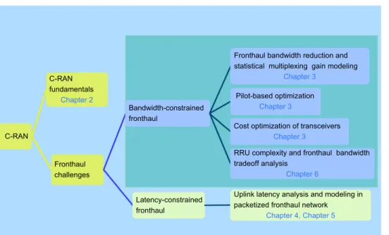
Fig. 1.1.Overview of thesis outline highlighting the main research problems and their associated chapters.
• Chapter 5 extends the model in Chapter 4 to a discrete-time queuing in order to account for the slotted nature of transmissions. The main reason for the discrete-time queuing is that the arrival process occurs only at the slot boundaries, and service time is also discrete, meaning that the service time requires just an integer number of the slot duration. This chapter presents a novel queuing model to characterize the distribution of queuing delays at an aggregation gateway in the uplink (UL). This yields tractable, closed-form expressions for the generating functions of steady-state queue length and sojourn time distributions. The analytical results are verified by numerical simulations. The proposed model is then used to study the probability of an outage, which occurs when the sojourn time exceeds the delay budget. It is illustrated that the outage probability decreases as the fronthaul capacity increases. Moreover, it shows that owing to statistical multiplexing, the fronthaul capacity per RRU required to meet a delay constraint significantly decreases when traffic is aggregated from a higher number of RRUs. The publication related to this chapter is:
– J. Francis, J. K. Chaudhary, A. N. Baretto and G. Fettweis, “Uplink latency in massive MIMO-based C-RAN with Intra-PHY functional split”, IEEE Com-munications Letters (CL), 2020, pp. 1-5.
• Chapter 3 shows that required fronthaul data can be significantly reduced by of-floading a part of baseband functionalities to the RRU. However, this increases the complexity at the RRU. Chapter 6 analyzes the RRU complexity and fronthaul bandwidth tradeoff. In addition, functional split with a detailed RF chain is taken into account, together with 5G NR flexible numerology. The publication related to this chapter is:
employ-6 1 Introduction ing xRAN functional split: complexity analysis for 5G NR remote radio unit,"European Conference on Networks and Communications (EuCNC), Va-lencia, 2019, pp. 1-6.
• Finally, Chapter 7 concludes the thesis summarizing the core findings of the works presented in this thesis. In addition, it provides possible future directions and some open research problems.
For better illustration, the overall thesis structure is illustrated in Fig. 1.1 correlating the main research problems and their associated chapters.
Chapter 2
Radio Access Network Architecture
As stated in Chapter 1, the traffic demand from the mobile users is surging. Some of the alternatives to cater increasing traffic demand are [WZHW15]: (1) employing ad-vanced transmission techniques such as (massive) MIMO and beamforming; (2) using higher bandwidth channels with millimeter wave (mmWave); (3) exploiting spectrum holes through dynamic spectrum access technologies such as cognitive radio (CR), and (4) de-ploying a large number of small cells. The first approach has made a significant progress in the recent decades and is approaching a practical limit [WZHW15]. The second approach requires normally line-of-sight (LoS) communications. The third one cannot ensure consis-tent and reliable services [WZHW15]. The fourth one takes advantage of frequency reuse, which will introduce more interferences. However, the interference can be mitigated by ad-vanced cell coordination and cooperation schemes. Introduction of adad-vanced radio access techniques, particularly massive MIMO, mmWave, carrier aggregation, and deployment of small cells has placed a stringent requirement in the transport network to carry massive amounts of data with a minimum delay from hundreds of thousands of cells [RWN+18].
Hence, the evolution of radio access networks needs to be complemented by the evolution of the transport network, thus demanding the redesign of the future transport technolo-gies. To this direction, C-RAN architecture has been introduced [Chi13]. In C-RAN, the processing resources can be centralized (and even virtualized) at a pool and are shared among many RRUs. In addition, it features real-time cloud computing and power effi-cient infrastructure. In this chapter, we recap C-RAN architecture, present its potentials and the challenges of C-RAN deployment for 5G. Furthermore, we analyze how C-RAN challenges can be relaxed by means of functional splitting. This pushes the conventional C-RAN approach towards a packetized fronthaul network. In a packetized fronthaul, ran-dom packet delays due to queuing at switching/aggregation gateways can occur and it is necessary to characterize distribution of queuing delays. Hence, queuing theory is also presented. This chapter builds essential groundwork for the remaining chapters.
8 2 Radio Access Network Architecture
2.1
Cloud Radio Access Network Architectures
2.1.1
Radio Access Network Architecture Overview: From
D-RAN to C-D-RAN
The conventional RAN architecture (also termed as D-RAN) shown in Fig. 2.1 (left) has a standalone BS, which performs all analog, digital and power functions at a dedicated location, and the RF signal generated by BS’s RF unit is carried to and from antennas mounted on the rooftop through coaxial cables. As coaxial cables are lossy, signal is degraded before it reaches to antennas. Moreover, in order to accommodate more data traffic, many BSs need to be deployed. Although this increases wireless throughput per unit area, this might cause interference among the BSs, as BSs are closer to each other and they might be reusing the frequency. It is reported in [Chi13] that the majority of power consumption is coming from BSs, but the BS power efficiency is only 50% because inside the BS, only half of the power is used by RAN equipment and the remaining half is used by air conditioners or coolers and other facilitate equipments. Therefore, deployment of more BSs will cause more energy consumption, resulting in higher OPEX and a significant environmental impact. Furthermore, often the average utilization of the BSs is much lower than the peak utilization, which causes waste of the processing resources and power at idle times [Chi13]. Thus, the legacy networks are inefficient in handling spatio-temporal variations, known as tidal effect, of the underlying traffic demand [GRI+17]. Moreover, the system flexibility for easy updates or upgrades is very limited.
Fiber – Digital baseband Coaxial cable – RF
Fig. 2.1.RAN evolution from legacy D-RAN (left) to C-RAN (right) through centralized RAN (center).
D-RAN has very high CAPEX and OPEX, making it not an economical and viable solution for next-generation mobile networks. In order to overcome D-RAN disadvantages, a centralized RAN architecture evolved as shown in Fig. 2.1 (middle), where the RF part is separated from the BS, and moved to a low-cost, small and light-weight form-factor remote radio head (RRH) deployed at the antenna site, and the BS performs only the baseband signal processing functions at a central location, known as BBU. The RRH is connected to a BBU by means of a transport link, known as fronthaul1, using radio over fiber (RoF) transmission technologies. The RoF can be digital or analog [FSM+15].
1In contrast to fronthaul, there is a transport link, known asbackhaul, which connects the BBU to the core network (CN).
2.1 Cloud Radio Access Network Architectures 9
For the transport of fronthaul traffic, the main specifications defined by radio equipment manufactures based on digital radio over fiber (D-RoF) transmission technique are CPRI [CPR15], open base station architecture initiative (OBSAI) [OBS06] and open radio inter-face (ORI)2 [ORI15], whereby the radio signal is sampled, quantized and encoded before being transmitted over the fronthaul. CPRI and OBSAI specifications differ3 in the way
how information is transmitted [dHLA16, SS14a]. The most widely adopted protocol by the vendors is the CPRI. Another D-RoF solution is an ongoing work in IEEE 1914.3 [NGFa] to define a radio over Ethernet (RoE) solution. The BBU transports or receives usually the digitized baseband samples, preferably4 by means of dedicated optical fiber links. Generally, BBUs can transport or receive also the analog radio signal by means of analog radio over fiber (A-RoF) techniques. However, A-RoF techniques [HG14] are not as often deployed as their digital counterparts for the following reasons: firstly, A-RoF is not yet standardized and secondly, D-A-RoF is mostly preferred due to inherent advantages of digital solution, such as its immunity to noise and hardware impairments, and flexibility in the transport deployment. In the centralized RAN, each BBU connects only one RRH through a dedicated fiber. Hence, it lacks coordination among the BBUs and normally has no or only limited resource sharing. Inheriting the benefits of cloud computing, the centralized RAN architecture has evolved to a cloud-based RAN architec-ture, known as C-RAN, shown in Fig. 2.1 (right). In C-RAN, one or several of RRUs are connected to a pool of BBUs, often referred to as BBU pool, thus offering efficient utiliza-tion of BBU resources. Some tutorials and overview papers on C-RAN can be found in [CCY+15, WZHW15, ATM18]. C-RAN offers several advantages, which are listed below:
C-RAN Advantages
• Reduction of total cost of ownership (TCO), and lower energy consumption owing to centralization of RAN functionalities at the BBU pool;
• Simpler and cheaper operations and maintenance, and easy centralized system up-dates and upgrades;
• Easier implementation of advance coordinated and cooperative signal processing functions, such as coordinated multi-point (CoMP), enhanced intercell interference coordination (eICIC), joint transmission (JT) and joint reception (JR), which are essential to improve the spectrum efficiency, link reliability, and the communication quality, particularly of the cell-edge users;
2ORI was introduced by the European Telecommunications Standards Institute (ETSI) to address CPRI comparability issue and to provide better compatibility among vendors.
3CPRI is a serial constant bitrate (CBR) interface, whereas OBSAI is a packet-based interface. OBSAI was established in 2002, before CPRI. The first version of CPRI specification was released at the end of 2003. It is worth noting that CPRI has less overhead compared to that in OBSAI, which makes it more advantageous to implement. Another significant advantage of CPRI is that the BER requirement in CPRI is10−12, which is less strict than the OBSAI BER requirement of10−15.
4In addition to optical fiber, mmWave, microwave or any other access link media can also be used. However, unlike optical fiber, mmWave and microwave are used for shorter distances and preferably in LoS communications.
10 2 Radio Access Network Architecture • Efficient hardware utilization through resource sharing and network function
virtu-alization (NFV) offering statistical multiplexing gains; • Scalability to add/remove/upgrade services as required.
Challenges in Fronthaul
Implementing C-RAN architecture in the existing 4G mobile networks has several ad-vantages, which are listed above, but implementing C-RAN in a 5G network is quite demanding. Particularly, deploying a reliable fronthaul network for future RATs in a cost- and energy-efficent way, while still satisfying the stringent fronthaul bandwidth and latency requirements is enormously challenging [RWN+18]. In order to enable efficient centralized and cooperative processing, the fronthaul links must offer huge bandwidth, very low-latency and jitter, and very tight synchronization. Unfortunately, the practi-cal fronthaul is often capacity- or delay-constrained [PWLP15]. These two contraints – excessive fronthaul bandwidth and extremely low-latency – on the fronthaul are the ma-jor obstacles in the deployment of C-RAN architecture. The core of the thesis are these constraints, which are explained below.
• Challenge 1: Fronthaul has a Capacity Bottleneck
The current C-RAN architecture is designed for 4G mobile networks and the fronthaul transports digitized I/Q- (in-phase/quadrature-phase) samples using the CPRI protocol. The required fronthaul data rate per sector (in bits/s), in general, is given by [DDM+13]
DCPRI =NAnt·fs·NQ,opt8·2·ζopt8, (2.1)
where NAnt is the number of antennas at the RRU, fs the sampling rate (in
sam-ples/s/carrier), NQ,opt8 the resolution of time-domain quantizer (in bits/sample), 2
is a multiplication factor to account for I/Q samples, and ζopt8 = γCW ·γLC is a
CPRI specific overhead factor, where γCW represents the overhead introduced by
CPRI control words5 (typically one control word for 15 words of payload data), and
γLW represents the line-coding overhead (e.g., 10/8 for 8B/10B coding or 66/64 for
64B/66B coding).
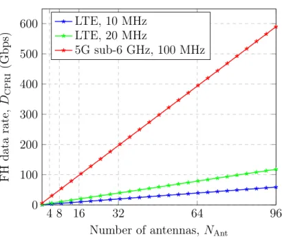
As seen from (2.1), the required CPRI bandwidth scales linearly with the number of antennas and sampling frequency (and thus with the applied transmission band-width on the access link). The next-generation mobile systems are envisaged not only to support carrier aggregation and multi-band, but also to integrate new radio access techniques, such as massive MIMO and mmWave communications [ATM18, R+13]. Therefore, the next-generation mobile systems will induce huge fronthaul bandwidth demands, which makes fronthaul networks deployment non-affordable. As illustrated in Fig. 2.2, a 100 MHz 5G sub-6 GHz massive MIMO system employing 96 antennas 5A CPRI basic frame consists of 16 words, where the first word is used for a control word and the remaining 15 words are used for payload data.
2.1 Cloud Radio Access Network Architectures 11 4 8 16 32 64 96 0 100 200 300 400 500 600
Number of antennas, NAnt
FH data rate, DCPRI (Gbps) LTE, 10 MHz LTE, 20 MHz 5G sub-6 GHz, 100 MHz
Fig. 2.2. Fronthaul data rate per sector in a 10 MHz, 20 MHz LTE and 100 MHz 5G sub-6 GHz with respective sampling frequencyfs={15.36,30.72,153.6}MHz. (NQ,T= 15,γCW= 16/15andγLC= 10/8)
requires roughly a60times larger bandwidth (DCPRI ≈590Gbps), when compared
with a 20 MHz 8×8 LTE (DCPRI ≈9.8 Gbps). The required fronthaul bandwidth
is extremely high and possibly too expensive for practical fiber deployment. Hence, the fronthaul could become a bottleneck for the performance of the future mobile networks, if it is not dimensioned correctly [HR16, Chapter 4]. Furthermore, the bandwidth requirement of CPRI-based fronthaul is fixed for a given cell configura-tion6 and does not depend on the amount of real traffic associated with the cell.
As a result, for example, to support a peak UL user data rate of 150 Mbps in a 20 MHz single-sectored 8×8 LTE, UE Cat 8 [3GP19, Table 4.1-2], roughly 50 Gbps constant fronthaul bandwidth is required for CPRI-based fronthaul in a 5G network, irrespective of RRU’s real traffic load.
Methods to Mitigate Fronthaul Capacity Bottleneck
In order to ease the challenging fronthaul data requirements, various solutions have been proposed, such as (i) decreasing the fronthaul required data rate [Chi13] e.g., by reducing the signal sampling rate, applying non-linear quantization, or using com-pression techniques ( I/Q data comcom-pression, subcarrier comcom-pression) (ii) increasing the fronthaul capacity using single fiber bidirection (SFBD), wavelength division multiplexing passive optical network (WDM-PON) [CLHD+14, 5G-a], optical trans-port network (OTN), time shared optical networks (TSON) [ZTA+11, YQZ+12] or
mmWave communication [PM17, PM17]. Vendors have shown that the fiber con-sumption in LTE deployments can be saved by half using CPRI compression tech-niques, such as 2:1 compression with lossless performance [LC13]. In addition, using a SFBD technology, which allows simultaneous UL and DL transmission on a single 6Even the most recent CPRI specification [CPR15] has a maximum supported data rate of about 24 Gbps per cell.
12 2 Radio Access Network Architecture fiber, the fiber consumption can be further halved. Thus, combining CPRI com-pression and SFBD, fiber consumption can be saved threefold [Chi13]. However, fiber consumption reduction using these techniques are not enough for 5G fron-thaul, mainly because the 5G fronthaul requires an enormous bandwidth and there is a growing complexity associated with the compression techniques. Alternatively, redefining the current functional split architecture between the BBU and RRU by splitting the signal processing functions in different ways has been considered as a promising architecture by several standardization bodies and forums, such as 3GPP [3GP17a], CPRI consortium [eCP19], next generation fronthaul interface (NGFI) [NGFb], NGMN Alliance [NGM15b] and Small Cell Forum [Sma15]. This approach moves the current CPRI architecture towards a packet-based network, such as Eth-ernet with new functional splits between BBU and RRU [DDM+13, WRB+14], as
it will be explained in Section 3.1. Data needs to be encapsulated in the form of packets rather than a constant stream in CPRI. Hence, a packet switching protocol such as Ethernet can be used, which allows us to enjoy inherent benefits of Ethernet, such as its cost effectiveness, ubiquity and flexibility.
• Challenge 2: Fronthaul is Latency-constrained
The latency constraint in the fronthaul originates either from the timing require-ment of the hybrid automatic repeat request (HARQ) or from use cases, such as Tactile Internet, autonomous driving or augmented and/or virtual reality. In the LTE MAC, the HARQ process is co-located7 with a scheduler and it requires the acknowledgement signal to be sent within a pre-defined round-trip time (RTT) de-noted as Tmax, delay. Most of the RTT Tmax, delay is spent at the BBU and RRU for
baseband signal and RF processing, respectively, and the remaining time TFHis left
for the fronthaul transport. In general, the latency budget left for the fronthaul with the HARQ process located at the BBU is a few hundreds of microseconds, typically
TFH ≤250 µs [3GP17a, SS14b]. The main latency components in the fronthaul are
analyzed here. The RTT delay between the BBU and RRU is considered, which con-sists of mainly three parts: delays in the access link, delays in the fronthaul network and delays in the RRU and baseband processing. These latency components can be broken down, for simplicity, into transmission delay, propagation delay, processing delay, packetization delay, fabric delay and queuing delay. Therefore, the round-trip fronthaul latency can be obtained as [3GP17a, SS14b]
TFH=Tmax, delay−2(Ttrans+TProcRRU+TProcBBU +TpropRAN), (2.2)
where,Tmax, delay is 8 ms HARQ RTT in FDD LTE,Ttrans =packet size/FH bitrate8
the transmission delay,TRRU
Proc the processing delay at the RRU,TProcBBU the processing
delay at the BBU andTpropRAN the propagation delay in the RAN.
7The HARQ timing requirement is very critical if HARQ is located at the BBU, however, the timing requirement is much relaxed if the process is located at the RRU [3GP17a].
2.1 Cloud Radio Access Network Architectures 13
The signal is packetized in the fronthaul and it also requires certain time to propa-gate in the fronthaul. Hence, the round-trip fronthaul latency can be given by
TFH = 2 N X i=1 Tq,i+TpropFH +N(Tf+Tpkt) ! , (2.3)
where, Tpkt = packet size/switch speed the packetization delay, TpropFH is the
propa-gation delay in the fiber,Tf the fabric delay, Tq,i the queuing delay for theith switch andN the number of switches. Packetization delay is the time required to packetize data samples into a packet. Fabric delay is the delay in the hardware of a switch and depends on the quality of the switch. Fabric delay value is very low, typically in the order of nanoseconds or a few microseconds. Note that fronthaul delay contains deterministic terms for a given scenario but the queuing delay will be variable. Focus of the thesis is to characterize the queuing delay distributions at the switch, which is presented in Chapter 4 and Chapter 5.
The low-latency requirements place a limit on the separation between the BBU and RRU. Thus, knowing the allowable fronthaul latency, the maximum (one way) distance between the BBU and RRU can be computed using dFH, max = TFH/∆TP,
where,∆TP is the round-trip propagation delay per km, which is 10µs/km for
fiber-based fronthaul. Typically, the maximum separation between the BBU and RRU is 25 km.
2.1.2
Flexible RAN Architecture: Birth of Functional Split
Researchers must find new possibilities for lowering the stringent fronthaul requirements stated above, while still benefiting from the acclaimed C-RAN benefits stated in 2.1.1. One possibility is to revisit the traditional concept of C-RAN, by allocating more functions locally at the cell site, and, thus, processing the signal more before being transported to the BBU. However, the important question is how many functions should be kept locally at the cell cites and how many should be left for central processing? Well, to this end, several functional subdivisions, also called functional splits, are under consideration by 3GPP [3GP17a], CPRI consortium [eCP19], NGFI [NGFa], NGMN Alliance [NGM15b] and Small Cell Forum [Sma15]. Functional splitting refers to the division of signal pro-cessing functions between the BBU and the RRU, and each functional split corresponds to a split point (split option). 3GPP [3GP17a] has defined eight functional splits with sub-options for some of the splits. It is to be noted that although a higher-layer split (HLS) (Option 2) has already been agreed upon, still no consensus has been reached yet (at the time of thesis writing) for a lower-layer split (LLS) [AZH+18]. The functional split naming is varying among the organization bodies and forums, but we restrict ourselves to the 3GPP numerology. For the mapping of the numerologies, 3GPP and eCRPI are compared in Fig. 2.3, as these two have been widely presented. For numerologies mapping among all leading organization, refer to e.g., [Cha, Figure 2.2] or [LCC19, Figures 7 and 8]. LTE protocol stack is considered in this work and an overview of 3GPP splits with their required data-rate and latency requirements is presented. Note that in 5G RAN, a BBU
14 2 Radio Access Network Architecture Modulation • Layer mapping • Precoding D/A conversion, RF RRC RE mapping IFFT, Add CP Channel coding • Rate matching • Scrambling PDCP Variab le FH BW Co nsta nt F H B W RLC Upper RLC Lower RLC IP
MAC Upper MAC
Lower MAC De-modulation • Equalization • Channel estimation A/D conversion, RF RRC RE De-mapping Remove CP, FFT Channel De-coding • De-scrambling • De-interleaving • Rate de-matching PDCP RLC Upper RLC Lower RLC IP MAC Upper MAC Lower MAC Split E Opt 8 TD IQ samp le s FD IQ samp le s Opt 7.1 Split ID Opt 7.3 Split IID/U Opt 7.2 Split D Opt 6 Opt 3 Split C Opt 4 Split B Opt 2 Split A Opt 1 RRU Co m pl ex ity Sma ll La rg e Opt 5 FH Ba ndw idt h La rg e Sma ll FH La ten cy Low Rel axed 3GPP eCPRI
Fig. 2.3. LTE protocol stack with functional splits proposed by 3GPP[3GP17a], CPRI consortium [eCP19]. The RF, PHY layer (Layer 1), data link layer (Layer 2) and network layer (Layer 3) are repre-sented by light purple, light green, light blue and light gold colored functional blocks, respectively.
is further divided into two segments: a distribution unit (DU) and a control unit (CU). The DU is located close to the user, and the CU is located in a datacenter and virtu-alized. The transport link connecting DU to CU is known as midhaul. Throughout this thesis, we interchangeably use BBU/CU for the baseband unit and RRH9/RRU/RU for
distributed radio elements. Moreover, capacity-constrained fronthaul is loosely used in place of bandwidth-constrained fronthaul.
Fig. 2.3 illustrates the eight functional splits with LTE protocol stack as a reference. This figure shows how the received signal by the antennas are transmitted via the antennas ports for processing into the PHY layer, then to the network layer through the data link layer. Reverse operations occur in the downlink (DL). The red lines in the figure represent different functional splits names. They mean that the functions below the split line are executed locally at the RRU, while those above the split line are performed centrally at the BBU. Furthermore, as we move towards higher-layer splits (with smaller split numbering in 3GPP naming), a signal is processed more locally, before being transported to the BBU. The more the signal is processed locally at the RRU before the data is transported to or from the BBU, the lower the bitrate on the fronthaul.
In the UL, the radio signal received by the antenna is first filtered, amplified and then down-converted to a baseband signal, which is then sampled, quantized and encoded to get the time-domain signal. The digitized time-domain I/Q samples are sent for processing 9Strictly speaking, the RRH and BBU are terminologies used in LTE.
2.1 Cloud Radio Access Network Architectures 15
into the PHY layer. Next, the cyclic prefix (CP) is removed and the fast Fourier trans-form (FFT) operation is applied, resulting into the frequency-domain I/Q samples, i.e., subcarriers in frequency-domain. After the FFT, the guard subcarriers are removed. For example, in a 20 MHz LTE, where we have a total of 2048 subcarriers corresponding to 100 physical resource blocks (PRBs), 848 subcarriers are guard band subcarriers, which are removed, leaving only 1200 usable subcarriers. Hence, this brings a drop of approximately 40% fronthaul bitrate. Next, the subcarriers are demapped by the resource element (RE) demapper and only the allocated PRBs are transported in the fronthaul. This makes the fronthaul data rate vary with the actual user load. Thus, the RRU with included RE demapper/mapper makes the fronthaul data rate varying, which is illustrated by an ar-row on the left hand side of Fig. 2.3. Note that the RRUs without demapper/mapper will have CBR traffic.
In the PHY layer, de-modulation, rate de-matching and de-scrambling are carried out, which further reduces the rate depending on the order of modulation. Next, we describe the individual fronthaul data rate for selected splits. The design of the fronthaul transport network is affected by the choice of a functional split, as each split has its own advantages and disadvantages, e.g., in terms of required bitrate and latency. In this work, only the default CPRI split (Option 8), PHY layer splits (Options 7.1,7.2 and 7.3) and MAC-PHY split (Option 6) are considered and their bitrate are calculated. For detailed fronthaul bitrate calculations, please refer to, e.g., [DDM+13], [Sma15, Appendix C], [R3-16b] and [R3-16a, Table 1]. Note that the peak fronthaul data rates are calculated for each sector. Hence, the net peak fronthaul data rate can be obtained by multiplying the per sector peak fronthaul data rate with the number of sectors. The description of the symbols in the rates calculation and their numerical values are listed in Table 2.1.
• Option 8:
This split is similar to the classical CPRI split, where all the RF processing such as amplification, filtering, A/D or D/A conversion is performed at the RRU, while leaving aside all the baseband signal processing functions at the BBU. Time-domain I/Q samples are transported using a fronthaul interface. Being a conventional de-facto split in C-RAN, this inherits all the benefits listed in Section 2.1.1. The major disadvantage of this split is that it requires a continuous bitrate transport, irrespec-tive of whether user traffic is present or not. Thus, Option 8 seems impractical for 5G RATs, as it requires a prohibitively high bit rates and a very low-latency (as explained in Section 2.1.1). The fronthaul data rate for Option 8 can be calculated as
Dopt8=NAnt·fs·NQ,opt8·2·ζopt8. (2.4)
• Option 7.1:
At this split, FFT/inverse fast Fourier transform (IFFT) and CP removal/addition are done at the RRU. Thus, frequency-domain I/Q samples of all PRBs are for-warded. The fronthaul data rate for Option 7.1 can be calculated as
16 2 Radio Access Network Architecture
Tab. 2.1.Parameters for fronthaul data rate calculation.
Parameters Symbol Unit LTE sub-6 GHz
Carrier frequency fC GHz 2 2
Channel bandwidth B MHz 20 100
Sampling frequency fC MHz 30.72 153.6
Number of resource blocks NRB - 100 500
Number of active
subcar-riers per RB N
RB
SC - 12 12
Number of symbols per
subframe N
SF
sym - 14 14
Subframe duration TSF−1 s 1 1
Number of antennas NAnt - 8 96
Number of antenna ports
(ADC/DAC chains) NPort - 4 8
Number of spatial layers NLayer - 4 8
Quantizer bit resolution per I/Q dimension
{NQ,opt8, NQ,opt7.1, NQ,opt7.2,NQ,opt7.3, NQ,opt6} bits {15,9,9,3,1} {15,12,12,3,1} Maximum utilization µ - 1 1 Resource overhead η - 0.1 0.1 Fronthaul overhead {ζopt8, ζopt7.1, ζopt7.2, ζopt7.3, ζopt6} - 4/3 4/3
Modulation order Mmod - 64 256
Code rate Rc - 5/6 5/6 Dopt7.1 =NAnt·NRB·NSCRB·N SF sym·T −1 SF ·NQ,opt7.1·2·ζopt7.1. (2.5)
Note that sampling frequency is now replaced by the product of the number of resource blocks NRB, number of subcarriers per subframe NSCRB, number of
sym-bols per subframe NSF
sym and the subframe duration T
−1
SF. In addition, it includes
frequency-domain quantizer resolution NQ,opt7.1 instead of the time-domain
quan-tizer resolution NQ,opt8. Note that different quantization resolution bits are used in
different splits [DDM+13] depending on the dynamics of the signal. In Option 8, as
signal signal has a higher dynamic range, a higher number of quantization bits (e.g., 15 bits per I/Q dimension) is used. After FFT and resource demapping, a fewer number of quantization bits are used.
• Option 7.2:
The fronthaul data rate for Option 7.2 can be calculated as
Dopt7.2=NPort·NRB·NSCRB·NsymSF ·T
−1
SF ·µ·NQ,opt7.2·2·ζopt7.2. (2.6)
Resource element mapping/demapping is performed at the RRU. Only the allocated subcarriers are transported in the fronthaul. The fronthaul data rate is coupled with the actual cell load because only the resources occupied by the user data transmission
2.1 Cloud Radio Access Network Architectures 17
need to be forwarded. Hence, this makes the resultant fronthaul data rate variable and this allows to obtain statistical multiplexing gains.
• Option 7.3:
The fronthaul data rate for Option 7.3 can be calculated as
Dopt7.3 =NLayer·NRB·NSCRB·NsymSF ·T
−1
SF ·µ·(1−η)·NQ,opt7.3·log2(Mmod)·ζopt7.3. (2.7)
This split resembles Option 7.3 in 3GPP and is defined only for the DL. This split exhibits asymmetry in the UL and DL because it differs how the information bits are transported in the UL and DL. In the DL, encoded user bits are forwarded, whereas in the UL, one log-liklihood ratio (LLR) value per information bit is forwarded. Each LLR is typically represented by 3 bits. Thus, depending on the used modulation scheme, it requires NQ,opt7.3 ·log2(Mmod) bits. Furthermore, the data rate depends
now on the number of spatial streams (spatial layers) NL, instead of on the number
of antenna ports (number of ADC/DAC chains). The number of spatial streams and the modulation scheme depend on the user’s channel quality. Suppose that the channel quality of a certain user is not good enough to have a permissible spatial separation between the independent streams, then only the supported streams need to be forwarded, instead of one stream for each antenna [HR16, Chapter 4]. Note that this dependency on the spatial layers, particularly for massive MIMO employing hundreds of antennas, is really significant, because the required fronthaul bitrate is reduced a lot. Otherwise the fronthaul would require a tremendously high data rate. Moreover, reference symbols no longer need to be forwarded, since the channel estimation and equalization are done at the RRU. Hence, the fronthaul bitrate is further reduced by a factor 1−η, where η is the resource overhead. Thus, these dependencies make fronthaul traffic more coupled to the actual user traffic.
• Option 6:
This split marks a separation point between the PHY and MAC layers. Thus, the RRU executes all the PHY as well as RF layer functions, whereas the BBU performs the data and the network layer functions. The data rate in this split is determined by the transport block sizes (TBSs) and bit-level user data is transported. Decod-ing/coding removes/add extra redundant bits from/to the actual information bits. No redundant bits are forwarded. Hence, the fronthaul bitrate is further reduced according to the code rate Rc. Decoder output are information bits. Hence, the
quantizer resolution is one bit, i.e., NQ,opt6 = 1. The fronthaul data rate for Option
6 can be calculated as
Dopt6 =NLayer·NRB·NSCRB·N SF sym·T
−1
SF ·µ·(1−η)·NQ,opt6·log2(Mmod)·Rc·ζopt6. (2.8)
Fig. 2.4 shows illustrates fronthaul data rates for five splits (Options 8, 7.1,7.2, 7.3 and 6) and two RATs (LTE and 5G sub-6 GHz). The parameters are justifiably chosen to cal-culate the bitrates and are listed in Table 2.1. 5G sub-6 will have higher bandwidth with
18 2 Radio Access Network Architecture
Option 8 Option 7.1 Option 7.2 Option 7.3 Option 6 10-1
100 101 102 103
Peak fronthaul data rate (Gbps)
LTE
5G sub-6 GHz
Fig. 2.4.Peak fronthaul data rates for Options 8, 7.1,7.2, 7.3 and 6 with SoTA LTE and 5G sub-6 GHz.
the aggregation of five carriers and higher-order modulation scheme. In [DDM+13], 7-9 bits are used for frequency-domain bit resolution and 64 QAM is considered. Sub-6 will also have a 256 QAM or even a higher-order modulation. Hence, for sub-6 GHz, a higher number of quantization bits are used. Furthermore, the number of antennas, antenna ports and spatial layers are considered from AIRRAYS’s massive MIMO RRU [5G-b], which have been tested with a field measurement in the 5G-XHaul project, where AIRRAYS GmbH (Xilinx Dresden GmbH) was an small and medium-sized enterprises (SME) part-ner. Note that the fronthaul overhead factor is different for different splits and depends e.g., on the transport medium and UL or DL direction. For example, if Ethernet is used as a fronthaul network, overhead is approximately 8% for Options 7.1 and 7.2, and 10.7% for Option 7.3, according to [NGM15a]. This overhead arises, e.g., due to synchronization, Ethernet frame and scheduling control. However, for the shake of comparison, the same overhead value is used for different splits, assuming fiber-based deployment. Moreover, maximum load utilization is considered, which yields peak fronthaul data rates.
Variable Fronthaul Data Rate: Enabler for Statistical Multiplexing
Gain
Many benefits of Ethernet can be obtained if the fronthaul data rate is variable. So, the interesting questions are: when does the fronthaul data rate become variable and how does the fronthaul data rate depend on the user? Which split generates a variable fronthaul split? This chapter investigates that and considers a suitable split for statistical multiplexing gain.
Considering the UL, time-domain samples are converted to frequency-domain samples after FFT operation. This reduces fronthaul data rate. However the reduction is only due
2.2 Packet-based Fronthaul Networks 19
to discarding a fixed set of guard carriers and removal of cyclic prefixes. This means, fronthaul data rate is still static in Option 7.1. Next, if the resource mapping is also done at the RRU (refer to Option 7.2), only the used subcarriers from the user are forwarded. As the number of allocated subcarriers vary among the users, the required fronthaul data rate is now coupled with the actual user data rate. Thus, statistical multplexing gains can be obtained as the fronthaul bit rate is varying. This is explained in Section 3.3.3. Hence, the lowest functional split for a variable fronthaul data rate is Option 7.2. Furthermore, more RRUs can be accommodated for a given fronthaul bandwidth if the fronthaul data rate is reduced.
Functional split latency requirements
In Option 5, HARQ and other timing critical functions are located at lower MAC. Hence, Options 1 to 5 will have relaxed latency requirements on the fronthaul link, whereas as Options 6 to 8 will have strict fronthaul latency requirements [LCC19]. In [Sma15, Ap-pendix B], one-way latency requirements on the fronthaul link are categorized in terms of ideal (0.25 ms), near-ideal (2 ms), sub-ideal (6 ms) and non-ideal (30 ms). In addition, 3GPP [3GP17a, Table A-1] has also proposed one-way fronthaul latency, which is max-imum 0.25 ms for Options 6 to 8, hundreds of microseconds for Option 5, approximate 0.1 ms for Option 4, max 1.5 to 10 ms for Options 2 and 3, and max 10 ms for Option 1. From both 3GPP and SCF, it is clear that the most critical latency on the fronthaul is the latency requirement of 250 µs.
2.2
Packet-based Fronthaul Networks
2.2.1
Standardisation Activities
Research on C-RAN has been conducted by many research organization as well as stan-dardization bodies. A few of them are recapped here.
The current fronthaul is based on the semi-proprietary CPRI protocol, which is by far the most adopted and the most popular RRU-BBU interface so far. However, CPRI is a serial CBR interface, and requires very high bandwidth and low-latency fronthaul links, which are foreseen to be challenging for 5G. To overcome these challenges, an evolved fronthaul is required to support 5G. In addition, as the demand of packet-switched technology is growing, recently a new industry standard enhanced CPRI, referred to as eCPRI, [eCP17, eCP19] has been released, which is designed for packet-based transport networks and supports real-time traffic. Moreover, a recent initiative IEEE 1914 working group for next generation fronthaul interface (NGFI) [NGFa] has shown that the stringent fronthaul requirements can be relaxed by using a packetized transport solution, such as Ethernet. IEEE 1914 work group has two active projects: (1) 1914.1 [IEEa], which is a standard packet-based fronthaul transport network, focusing on the architecture for the transport of mobile fronthaul traffic, and on defining the requirements (data rates, timing and synchronization, and QoS) for the fronthaul networks; and (2) 1914.3 [IEEb], which
20 2 Radio Access Network Architecture is a standard for RoE encapsulations and mappings, enabling encapsulation of digitized radio I/Q payload data as well as supporting the header format for both structure-aware and structure-agnostic encapsulation of existing digitized radio transport formats.
Ethernet is considered as a prime candidate technology for the evolved fronthaul due to its cost effectiveness through economies-of-scale, flexibility, and ubiquity. Furthermore, it supports NFV and software-defined networking (SDN) [SXT+19], and takes advantage of statistical multiplexing gains. Thus, it is clear that future RATs require the redesign of the fronthaul, leading to anevolved fronthaul. Thus, the consensus is towards a packetized fronthaul with a variable bitrate (VBR) functional split.
2.2.2
Challenges in Ethernet Fronthaul Network
Although Ethernet is considered as a transport medium for mobile fronthaul for RoE, due to its inherent advantages stated earlier, Ethernet does suffer, especially from low delay, delay variation, packet loss and tight synchronization requirements [BCV18]. Ethernet systems were not originally designed for delay sensitive networks. Hence, fulfilling the delay requirements by packet-switched Ethernet systems is identified as one of the main challenging requirements [BCV18]. Nevertheless, Ethernet can be used for the functional splits where these requirements are relaxed [MMM19]. The recently created Time-Sensitive Networking (TSN) Task Group [IEE18], which is a part of IEEE 802.1 Working Group, is working to develop new extensions to support Ethernet traffic forwarding, while providing guaranteed packet transport with bounded low latency, low packet delay variation, and low packet loss. Ethernet is natively asynchronous, which makes it not suitable for the transport of CPRI traffic as such. Thus, additional mechanisms need to be applied to Ethernet to make it suitable for the mobile fronthaul. Furthermore, for multi-hop connec-tion, it is mandatory to have synchronous Ethernet [dHLA16]. To this end, high Precision Time Protocol (PTP) over Ethernet, such as IEEE 1588 [IEE08] and Synchronous Eth-ernet (SyncE) [G.818] exist. PTP provides time synchronization, whereas SyncE provides frequency synchronization in packet-based Ethernet networks.
2.2.3
Ethernet Switch Structure
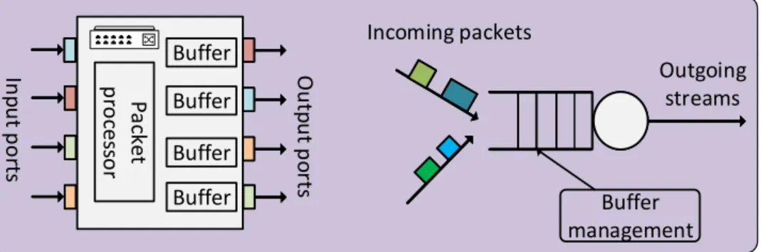
Fig. 2.5 shows a schematic illustration of an Ethernet switch and its output port structure. The switch consists of several input and output ports, a packet processor and buffer ele-ments. The packets are received at the input ports of the switch and are later forwarded to the packet processor. The switch reads and processes the source and destination medium access control (MAC) addresses of the Ethernet frame. The packet processor looks at the destination address of the packets and routes them to the appropriate output ports. Each output port has a buffer element and the packets are queued at the buffer at the switch output port. Each port has several queues, where packets can be sorted according to the priority of the queues and/or their traffic classes. Traffic can consist of a single homoge-neous traffic source or heterogehomoge-neous traffic sources with different QoS requirements, and different scheduling policies can be applied by the scheduler. The switch operation is con-trolled by the switch policy, which consists of a buffer management policy and a scheduling


![Fig. 3.9. Impact of standard deviation: Relative fronthaul capacity for different relative standard devi- devi-ations of the traffic density ( ¯ Ω), d corr = 50 m, P O = 0.01 [CBF17, CBF18].](https://thumb-us.123doks.com/thumbv2/123dok_us/10184419.2920942/49.892.255.664.120.466/standard-deviation-relative-fronthaul-capacity-different-relative-standard.webp)
![Fig. 3.11. Impact of outage probability: Relative fronthaul capacity for different outage probabilities (P 0 ), σ Ω /Ω = 0.5, d corr = 50 m [CBF17, CBF18].](https://thumb-us.123doks.com/thumbv2/123dok_us/10184419.2920942/50.892.220.630.124.468/impact-outage-probability-relative-fronthaul-capacity-different-probabilities.webp)
![Fig. 3.12. Impact of pilot optimization: Relative fronthaul capacity after optimization for K max (0) = 64 (left) and K max(0) = 128 (right) [CBF18].](https://thumb-us.123doks.com/thumbv2/123dok_us/10184419.2920942/51.892.123.795.114.448/impact-pilot-optimization-relative-fronthaul-capacity-optimization-right.webp)
