Microencapsulated Phase Change Materials in
Solar-Thermal Conversion Systems: Understanding
Geometry-Dependent Heating Efficiency and
System Reliability
Zhaoliang Zheng†, *, Zhuo Chang‡, Guang-Kui Xu§, Fiona McBride||, Alexandra Ho†, Zhuola Zhuola‡, Marios Michailidis†, Wei Li¶, Rasmita Raval||, Riaz Akhtar‡ and Dmitry Shchukin†,* †
Stephenson Institute for Renewable Energy, Department of Chemistry, University of Liverpool, Crown Street, Liverpool, L69 7ZD, UK.
‡
Centre for Materials and Structures, School of Engineering, University of Liverpool, Liverpool, L69 3GH, UK.
§
International Center for Applied Mechanics, State Key Laboratory for Strength and Vibration of Mechanical Structures, Xi'an Jiaotong University, Xi'an, 710049, China.
||
Surface Science Research Centre, University of Liverpool, Liverpool L69 3BX, UK.
¶ Chemical Engineering & Applied Chemistry, European Bioenergy Research Institute and Aston Materials Centre, Aston University, Birmingham, B4 7ET, UK.
KEYWORDS: Microencapsulation; Emulsification; Phase Change Materials; Nanocarbons; Encapsulation Ratio; Solar-Thermal Conversion; PF-QNM.
ABSTRACT
The performance of solar-thermal conversion systems can be improved by incorporation of nanocarbon-stabilized microencapsulated phase change materials (MPCMs). The geometry of MPCMs in the microcapsules plays an important role for improving their heating efficiency and reliability. Yet few efforts have been made to critically examine the formation mechanism of different geometries and their effect on MPCMs-shell interaction. Herein, through changing the cooling rate of original emulsions, we acquire MPCMs within the nanocarbon microcapsules with a hollow structure of MPCMs (h-MPCMs) or solid PCM core particles (s-MPCMs). X-ray photoelectron spectroscopy and atomic force microscopy reveals that the capsule shell of the h-MPCMs are enriched with nanocarbons and have a greater h-MPCMs-shell interaction compared to s-MPCMs. This results in the h-MPCMs being more stable and having greater heat diffusivity within and above the phase transition range than the s-MPCMs do. The geometry-dependent heating efficiency and system stability may have important and general implications for the fundamental understanding of microencapsulation and wider breadth of heating generating systems.
Solar-thermal conversion, where solar irradiation is harvested and converted to heat for beneficial usage, has gained renewed interest in the past decade and made it a special asset in energy conversions due to its operational simplicity and high energy conversion efficiency.1-4 Microencapsulated phase change materials (MPCMs, 1-100 µm diameter), often considered unique micrometer-scaled composites with a superior performance of latent heat thermal storage as compared with bulk PCMs, are currently emerging as positive additives/dopants to the solar-thermal conversion systems. Nanocarbon-stabilized MPCMs are of particular interest as they combine the advantages of nanocarbons for their outstanding energy conversion/transfer performance,5-7 MPCMs with an accelerated heat storage/release due to a relatively high surface-area-to-volume ratio8-13 and the PCM-nanocarbon interactions which often fosters an enhanced enthalpy and better crystallinity.14,15 A new avenue is therefore opening to enhance the heat-generating efficiency at a output temperature within and even higher than the solid-liquid phase-transition range (PTR).16-18 By constantly storing and retracting latent heat,19 the MPCMs are expected to maintain the dynamic equilibrium of output temperatures when the surrounding temperature is around the PTR. More attractively, since the liquid PCMs above PTR store a higher accumulative energy (latent heat + sensible heat) but exhibit a much lower specific heat capacity than the PCMs within PTR,20,21 the temperatures of PCMs and heat-generating structures would increase synchronously.22-28 Consequently, a higher energy storage capacity will be achieved;17 meanwhile, more heat will be emitted from the MPCMs above PTR to eliminate the convective heat dissipation in the heat-generating systems,29 resulting in an increased the overall output temperature.16
Despite the highly promising applicability of MPCMs to the solar-thermal conversion systems, manipulating their geometry in microcapsules to maintain stable encapsulation of PCMs and
effective thermal diffusivity is still challenging.30 The solid microspheres with a high surface-area-to-volume ratio are prevailing among the MPCMs covered by thick and non-nanocarbon capsule shells.9,31,32 The relevant statistics on the nanocarbon-stabilized MPCMs is largely unclear due to the difficulty in achieving the stable encapsulation of PCMs with flexible nanocarbon materials, for example graphene oxide (GO) or carbon nanotubes (CNTs), and even the nanocarbon-polymer composites. Furthermore, the undefined wettability between PCMs and nanocarbons28 induced by molecularly C-H···π interaction33-35 increases the complexity to examine the geometry of nanocarbon-stabilized MPCMs, its formation mechanism and influence on the heating performance. We hypothesize that solving these issues would benefit: (1) Confinement of the melted MPCMs within the micrometer-scaled nanocarbon microcapsules without leakage, leading to a reliable heat-generating performance and (2) Maximizing the utilization of the MPCMs per unit mass or volume within and above the PTR, which is a major drawbacks among the current MPCMs.10,18,36,37
In our previous study, we adopted CNT-reinforced GO hybrids as shell materials to encapsulate the alkane-type PCMs.16 The correlation between the C-H···π interaction and the thermal properties of MPCMs has been investigated, with a pronounced C-H···π interaction leading to stable encapsulation and fast thermal diffusivity. However, the geometry of MPCMs, which should have mediated the C-H···π interaction and the heating performance of MPCMs, and introduced a degree of complexity to the whole system, has not yet received the attention it deserves. In this work, by simply varying the cooling rates of emulsions, we realize the synthesis of controllable geometry of MPCMs within the nanocarbon microcapsules with a hollow structure of MPCMs (h-MPCMs) or solid PCM core particles (s-MPCMs). The structural variations between h- and s-MPCMs are then revealed by comparing carbon sp2/sp3 molar ratio
and surface mechanical properties of microcapsules. The structural effect of C-H···π interaction is quantified. The stark contrast in geometry may lead to differences in thermal storage capacity of the PCMs within PTR, stability of shell materials and position of the melted MPCMs above PTR, which have been confirmed by thermal analysis methods. The geometry-dependent efficacy of h- and s-MPCMs in energy conversion systems is investigated by using a graphene-based three-dimensional (3D) solar-thermal conversion system and a solar energy harvesting MPCM slurry as model, for a comprehensive understanding of the underpinning role of MPCM geometry on the overall performance, including heating performance and system reliability.
RESULTS AND DISCUSSION
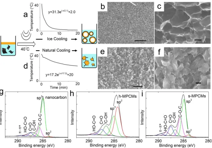
Fabrication of h- and s-MPCMs. To synthesize the MPCMs with controllable geometry, we modified the reported method16 by cooling down the ultrasound-induced nanocarbon-stabilized PCM (oil-in-water) emulsions (~40 °C) at two cooling rates (Materials and Methods). n-eicosane was utilized as a typical PCM for its moderate PTR (32 – 36 °C) and widely referenced structural and thermal property data. The dominant shape of emulsion droplets is near-spherical owing to the isoperimetric inequality38 during emulsification. To acquire h-MPCMs, the freshly-made emulsion was immediately cooled with ice water (~2 °C), leading to an exponential-like decrease of temperature (y) as a function of time (x): y31.3exp
x/2.1
2.0, with correlation factors higher than 0.995 (Figure 1a). The plateau referred to as the PTR of eicosane could barely be detected in the temperature plot, reflecting that the solidification finished almost instantaneously and the heat within the original liquid PCMs was extracted instantly in the presence of a relatively large T contrast. The resulting product preserves the original spherical morphology (Figure 1b) whereas the cross-sectional images (Figure 1c and S1) reveal a dominantly self-supporting hollow structure with a void ratio at around 80% that is determined by solid densityanalysis (see Supporting Information). The thickness of MPCMs within the solid phase is 100 to 200 nm, and thinner than the minimum requirement (300 nm) for a plastic interfacial phase that directs the formation of regularly shaped alkane microparticles.39 Meanwhile, the C-H···π featured MPCMs-shell interaction is unlikely to induce freezing adsorption layers at the interface due to the mismatch of molecular structures between alkanes and nanocarbons.40 As such, the instant adhesion of eicosane onto the inner surface of nanocarbon shell should be a direct preservation of original state of liquid MPCMs within the emulsion droplets. In comparison, the naturally cooled emulsion showed a clear PTR along at a much slower cooling rate:
/17.3
20 exp 2 . 17 xy , resulting in s-MPCMs. The morphology is that of
shrivelled-pods-like nanocarbon shells wrapping the irregular eicosane particles without clear boundary between capsules (Figure 1e, f). It is clearly shown that the slower cooling rate allows the long-chain alkane molecules to assemble into compact structures with a minimal MPCMs-shell contact area. Furthermore, thermogravimetric (TG) analysis (Figure S2) revealed the eicosane content in the microcapsules was higher for s-MPCMs (87.5 wt%) than h-MPCMs (75 wt%), reflecting a marked underutilization of nanocarbons in the s-MPCMs.
Characterization of h- and s-MPCMs with XPS. We employ X-ray photoelectron spectroscopy (XPS) to elucidate the effect of the geometry of MPCMs on the capsule shell composition. XPS C1s analyses of nanocarbon shell materials, h- and s-MPCMs were performed, as shown in Figures 1g-i. A typical spectrum of nanocarbons contain several components related to C=C (sp2, 283.6 eV), C-C (sp3, 285.0 eV), C-O (hydroxyl and epoxy, 285.7 and 286.7 eV), C=O (carbonyl, 287.5 eV), O-C=O (carboxyl, 288.6 eV) and pi-pi* (π-π*, 290.0 eV) groups.41,42 The relative atomic ratio of carbon sp2/sp3 is generally 1.0/45.3. However, more than half of the positions analyzed for the h-MPCMs sample exhibit a surprisingly high
sp2/sp3 ratio up to around 1.0/0.7. We cannot exclude the possibility of the removal of oxygen species during emulsification because the s-MPCMs sample has shown its increased sp2/sp3 ratio of around 1.0/17.5 and oxygen-species concentrations of the two MPCM samples have indeed decreased. However, since the XPS detection depth is ~10 nm and the thickness of nanocarbon capsule shell is 4.5 – 17.5 nm for h-MPCMs (Figure S3), such a high sp2/sp3 ratio detected can be mainly due to an enrichment of conjugative species from nanocarbons. The enrichment of nanocarbons would make the MPCMs-shell interaction more pronounced in the h-MPCMs than the s-MPCMs.
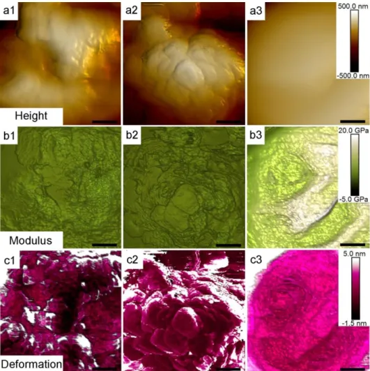
Mechanical properties of h- and s-MPCMs. We then examined the mechanical properties of capsule shells to quantify the MPCM-shell interaction. The atomic force microscopy (AFM) based Peakforce-Quantitative Nanomechanical Mapping (PF-QNM) enables real-time collection of topography (Figure 2a and S4) and mechanical properties that include elastic modulus (Figure 2b) and deformation (Figure 2c).43 Analysis of the capsule surface from topographic images disclosed a much rougher outer surface of h-MPCM capsules than that of s-MPCMs, with the surface roughness (Ra) at around 60 and 15 nm, respectively. This result can be explained by the rapid cooling which prompts the instantaneous solidification of eicosane close to the inner wall of capsules without enough time for the surface alkane molecules to form smooth facets. Furthermore, the fact (Figure 2a-2) that self-supporting nanocarbon shells are preserved even after removal of MPCMs, confirms the contribution of nanocarbons enrichment at the capsule shell. The overwhelming bright green colour of s-MPCMs in Figure 2b-3 indicates the highest elastic modulus among the samples. Consistent with Ra, h-MPCMs and nanocarbon shell (Figures 2c-1 and 2) show a similar heterogeneous distribution in the deformation mappings.
Such heterogeneity disappeared for s-MPCMs, as depicted in Figure 2c-3, which is in agreement with the alternation from hollow spheres to compact micrometre-scaled particles.
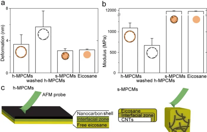
As shown in Figure 3a, the averaged deformation is greater for h-MPCMs (3.5 nm) than for either s-MPCMs (2.8 nm) or eicosane microcrystals (2.9 nm), which is consistent with the formation of a hollow structure. The self-supporting capsule shell deforms more than 6 nm, confirming the additional structural support of the MPCMs-shell interaction to the nanocarbon shell. The elastic moduli were also compared (Figure 3b). h-MPCMs (1094 MPa) and nanocarbon shell (671 MPa) exhibit lower moduli by more than one order of magnitude compared to that of s-MPCMs (11559 MPa) and eicosane microcrystals (11524 MPa). For hollow structures (Figure 3c, left), the elastic modulus of a quasi-2D composite perpendicular to the probing direction (Eh) can be calculated by Equation 1:
h ., inter h ., inter eico h eico, h , carbon h carbon, h h solid, E C E C E C E C (1)
where Ccarbon,h, Ceico,h and Cinter.,h represent the volumetric ratio of nanocarbons, free
eicosane and the interfacial zone between them, respectively; Ecarbon,h, Eeico and Einter.,h are
the corresponding elastic moduli. For simplicity, PCM confined inside CNT is not taken into account, and the effective interaction distance from the surface of GO or CNT is set at 4.3 Å.7 In the case that the volumetric ratio of solid phase Csolid,h is only 20 vol%, Ccarbon,h, Ceico,h and
h ., inter
C can be calculated to be 2.46, 16.5 and 0.25 vol%, respectively(Table S1). According to
Equation 1, Einter.,h is estimated at around 19 MPa, which is almost 20 times higher than that in
and Eeico, the supporting role of Einter.,h to the capsule shells has been witnessed. Moreover,
the volumetric fraction of CNTs in solid phase is estimated at around 0.37 vol% which is much higher than the initial feed ratio (0.03 vol%), again confirming the enrichment of nanocarbons in close proximity to the capsule shell.
For s-MPCMs, the simplified model of elastic modulus (Es) of the microcomposite can be
expressed as (Figure 3c, right):
s ., inter s ., inter eico s eico, CNT s CNT, s C E C E C E E (2)
because the nanocarbon shell has little effect on the mechanical properties of s-MPCMs but CNTs may still be embedded in the eicosane matrix due to the C-H···π interaction.26,28 The volumetric fraction of CNTs (CCNT,s) varies between 0 to 0.03 vol.% and modulus of
multi-wall CNTs was reported to be 900 GPa.45 If Einter.,s≈ Einter.,h≈ 19 MPa, CCNT,s in Equation 2
would be as low as 0.003 vol%, which is two orders of magnitude lower than that in h-MPCMs.
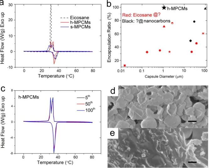
Thermal properties and structural stability of h- and s-MPCMs. The impact of geometry on the thermal properties of h- and s-MPCMs was examined by differential scanning calorimetry (DSC). In Figure 4a, h-MPCMs exhibit a rapid heat response to temperature variations without delayed solidification or subcooling circle in the freezing process,46 whereas s-MPCMs differentiates with a wider and delayed exothermic peak. The fast heat exchange between h-MPCMs and the environment may be due to the extensive C-H···π interaction surrounding the inner surface of microcapsules, which is consistent with literature reports that the C-H···π interaction enhances the interfacial thermal conductance.16,28,47 The average latent heat of h-MPCMs in PTR remains around 218.3 J/g, leading to an encapsulation ratio of eicosane as high
as 99.4% compared to the bulk state enthalpy (219.5 J/g). Despite the high cooling rate, h-MPCMs resemble s-h-MPCMs and bulk eicosane in crystallinity (Figure S5), forming a sharp contrast to the conventional MPCMs that often suffer from poor crystallinity as a result of slow thermal diffusivity and a lack of heterogeneous nucleation sites. As a consequence of the greater degree of crystallinity, more specific heat of MPCMs will be stored in the PTR. We compared the encapsulation ratio and size of h-MPCMs with previously reported shape-stable MPCMs (Figure 4b, Table S2). h-MPCMs with the highest encapsulation ratio and moderate size are found at the top of the diagram (black, solid star). The MPCMs with hollow structure clearly outperform the conventional MPCMs in terms of PCM utilization and applicable diameter in energy conversion systems.
The stable encapsulation after 100 melting/solidifying cycles was confirmed by using DSC, with little change in the melting/freezing point and enthalpy observed (Figure 4c). Figure 4d further shows negligible leakage of eicosane outside h-MPCMs when the temperature is above the PTR, even for broken capsules, implying a close adherence of MPCMs at the inner wall of capsules. Previous experiments within our group16 and others28 have confirmed the role of C-H···π interaction in increasing the wettability between alkanes and nanocarbons, and thus improving the thermal stability of the MPCMs.33,34 In contrast, a complete alternation from individual capsules to bulk eicosane covered with nanocarbons was seen for s-MPCMs (Figure 4e). This is because the insufficient C-H···π interaction cannot immobilize the liquid MPCMs, and thus induces the instability of s-MPCMs.
Solar-thermal conversions. To investigate how the geometry of MPCMs influences the overall solar-thermal conversion performance, we fabricated 3D graphene-based sponges incorporating the h-MPCMs or s-MPCMs microcapsules for solar-thermal conversion
experiments, and applied h- and s-MPCMs in solar energy harvesting MPCM slurries. We chose a 3D graphene-based photothermal sponge (Figure S6) as model for the following two considerations: (1) Its porous network and large surface area enable constantly rapid exchange of heat with the environment but meanwhile suffer from severe convective heat dissipation;29 (2) the graphene-based architecture without any reinforcement15 has weak framework stiffness48 and is vulnerable to even imperceptible structural failures, making itself an ideal platform for reliability test. The dopant ratio of h- or s-MPCMs microcapsules in the host structure was around 5 wt% and the corresponding sponges (diameter ~1 cm, height 0.8-0.9 cm) were then chemically reduced with hydrazine vapor (Materials and Methods). Under irradiation, a sensor inserted into the sponges was used to measure the temperature change of the photothermal model and a sponge in absence of MPCMs, thus without fusion heat, served as a control (Figure S7). Under the light intensity of ~200 W/m2, the sponge containing h-MPCMs maintains an equilibrium output temperature around the PTR (Figure S8), reflecting the effective role of MPCMs in constantly storing and retracting latent heat within PTR.19 Increasing the intensity of light to ~420 W/m2 drives the output temperature above the PTR. The photothermal performance endowed by the h-MPCMs microcapsules is even better than the control and the sponge containing s-MPCMs, with an equilibrium temperature above 50 °C. Moreover, the h-MPCMs samples experience an instant and smooth rise particularly at the PTR, whereas the kinks at the PTR are notable for the sponge containing s-MPCMs. In parallel, 25×25 µm2 confocal Raman mappings of the corresponding sponges indicate that h-MPCMs are well-retained within the capsules after irradiation above the PTR; while s-MPCMs almost disappear from the host structure (Figure 5b left and middle). Furthermore, the sponge containing the unstable s-MPCMs collapse as expected (Figure 5b right), which might be due to the destruction of s-MPCMs
microcapsules and leakage of liquid MPCMs into the fragile porous architecture. We speculate that the geometry-dependent stability of MPCMs is still valid when the MPCMs are incorporated in a more complex system and the detailed mechanisms for such contrasting results in the whole photothermal systems at different size regimes warrant further investigation.
To examine the role of geometry in a fluid flow, we investigate the photothermal performance of h- and s-MPCMs microcapsules in a phase change slurry model. Before the solar-energy harvesting evaluations, the capsules could be reduced only in one minute with the assistance of zinc powder and ultrasonication (Materials and Methods, Figure S9).49 h-MPCMs retain most of the PCMs in microcapsules but s-MPCMs do not (Figure S10). Under irradiation at ~420 W/m2, both the high-concentration (0.5 wt%) h-MPCMs slurry samples before and after reduction shows a clearly distinguished PTR (Figure 5c), evidencing the stable encapsulation of PCMs. At an analogous concentration (0.2 wt%), h-MPCMs microcapsules exhibit a superior output temperature to 62 °C in 30 min (Figure 5d) than those with less PCM but greater nanocarbon content (s-MPCMs and reduced GO). We should note that h-MPCMs have a slightly slower heating rate (T/t) below and within the PTR due to the highly efficient photothermal
conversion of nanocarbons5-7 and the effect of latent heat;36 however, the T/t of h-MPCMs
slurry becomes notably higher after the output temperature increases above the PTR (Figure 5e). Since the saturated temperature is always dependent on input power and convective heat dissipation,29 the superior performance of h-MPCMs might be due to the effective utilization of nanocarbons, PCMs or both. In our case the geometry-induced enrichment of nanocarbon and pronounced C-H···π interaction of h-MPCMs benefits respectively the photothermal activity and the utilization of MPCMs. Finally, the slurries containing 0.2 and 0.5 wt% h-MPCMs performed stably without notable degradation after at least 20 heating/cooling cycles (Figure 5f), with the
maximum and minimum temperatures changed slightly. There was no obvious aggregation, broken capsules or solid wax observed from the slurry (Figure S11).
CONCLUSIONS
The role of the geometry of MPCMs has been verified; furthermore, the corresponding MPCMs-shell interaction, particularly the C-H···π interaction between eicosane and nanocarbons at the inner wall of the microcapsules shell has also been quantified and exploited to enhance thermal diffusivity and reliability of MPCMs in solar-thermal conversion applications. Our special concentration on the geometry of MPCMs, often hidden beneath the capsule shell, and its influence on from molecular level to the whole system sets our work apart from previous studies on the microencapsulation of PCMs. We controllably synthesized MPCMs with either a hollow or solid structure (MPCMs or s-MPCMs) through tailoring the solidification process. h-MPCMs and s-h-MPCMs show a clear variation in the capsule shell composition and the h- MPCMs-shell interaction, which was examined by XPS and PF-QNM. The pronounced C-H···π interaction of h-MPCMs might be responsible for more stable encapsulation and greater heat diffusivity of melted MPCMs, as compared to s-MPCMs with only a weak MPCMs-shell interaction. Both supported and free photothermal conversion models show that h-MPCMs microcapsules exhibit a greater system reliability and output temperature than the s-MPCMs samples, due to the pronounced MPCMs-shell interaction. This work suggests that the difference in geometry can lead to a considerable variation of MPCMs-shell interaction and consequent efficacy of the whole solar-thermal conversion system. The underlying principle of geometry-dependent MPCMs-shell interaction holds great promise for widespread use of MPCMs in energy conversion systems and provides an economical modus operandi to effective and ultra-stable microencapsulation.
MATERIAL AND METHODS
Preparation of h- and s-MPCMs. Typically, the mixture of 5 mL of GO aqueous solution (2 mg/mL, pH = 2) and 0.2 mg of MWCNTs was pulse-sonicated (Model Q700, 20 kHz; Qsonica, USA) for 15 minutes (amplitude: 30%, 5 s on, 5 s off) with a 1.8 cm diameter titanium probe (model BS2d18F) in an ice-water bath and under protective nitrogen atmosphere. Then, 500 mg of eicosane was directly added into the as-prepared GO-CNT hybrid dispersion. The mixture was continuously sonicated for 3 min under a nitrogen atmosphere (amplitude: 30%, 10 s on, 5 s off) at a constant temperature of 40 °C. Upon completion of sonication, the reaction product was either cooled using an ice-water mixture or allowed to cool naturally. To record the temperature variation during the cooling step, a thermal sensor (VR105864, Vernier) was immersed into the freshly made emulsions. Temperature change of the sample was recorded by a data acquisition system (LabQuest2) through a connected thermal resistor and transmitted to a personal computer.
Formation of 3D graphene-based sponges. h- and s-MPCMs microcapsules were mixed well with GO solutions (4 mg/mL, pH = 2 - 3) before lyophilization. The weight ratio of MPCMs in the mixture were around 5 wt%. The mixtures were then cryogenically frozen by submersion in liquid N2 before being freeze-dried in a Virtis AdVantage freeze drier (duration: 48 h, shelf temperature: −90 °C). The reduction was finished through a hydrazine vapour method which was implemented overnight in a desiccator at 30 °C.50
Preparation of phase change slurry. The reduction of h- or s-MPCMs was conducted by ultrasonication (1 min, amplitude: 10%, 10 s on, 5 s off) of the fresh cooled microcapsules (pH = 2) with 100 mg Zn powder.49 The excess Zn powder was removed by washing with a large
amount of HCl solution (pH = 2). The suspension was directly mixed with an aqueous solution of 1 wt.% dodecylbenzenesulfonic acid (SBDS) in a 1:1 volume ratio. The mixtures were stirred for 30 min and then centrifuged (SIGMA 2-16 KL tabletop centrifuge) at 5000 rpm for 10 min to remove the excess Zn powder and any large aggregates.
XPS for composition test. The XPS data were recorded on a Kratos Axis Supra instrument (Kratos Analytical, Manchester, UK) using monochromatic Al Kα radiation (1486.7 eV, 225 W). Survey scan spectra were acquired using a pass energy of 160 eV and a 1 eV step size. Narrow region scans were acquired using a pass energy of 20 eV and a 0.1 eV step size. The hybrid lens mode was used in both cases. A charge neutralizer was used throughout as the samples were mounted such that they were electrically isolated from the sample bar. Several analysis points were analysed per sample. The spectra were calibrated to a binding energy of 285.0 eV for the hydrocarbon C 1s peak (sp3 peak) post acquisition. The data were processed and analysed using the Kratos ESCApe software. The carbon region was fitted with reference to the Ref 41, 42.
PF-QNM-AFM for mechanical property measurement. Mechanical property imaging was conducted with a Bruker Multimode 8 instrument (Bruker, Santa Barbara, CA, USA) operated with Peakforce Quantitative Nanomechanical Mapping (QNM) modality. Three parameters were calibrated firstly: deflection sensitivity, spring constant of cantilever and tip radius. We used Photostress polymer (Vishay Precision Group, Heilbronn, Germany) with a known elastic modulus (2.7 GPa) to calibrate the elastic modulus. Each scan was conducted with a resolution of 246 pixels/line and with a scan rate was 0.9 Hz. At least 5 images (size: 1 µm × 1 µm) were captured for each sample using the Bruker RTESPA-525 probes. Samples with a high stiffness were tested with TAP525 which has a nominal spring constant of 200 N/m and a tip radius of 8 nm. To prepare the AFM samples, the h- and s-MPCMs suspensions were casted and naturally
dried on a silicon slide. The washed h-MPCMs can be got by immersing the h-MPCMs AFM sample in hexane and washing it for at least three times, followed by freezing with ~1 mL pure hexane, and freeze-drying for 1 day.
Thermal analysis methods. TG used a Linseis microbalance (model STA PT1000) where the samples were heated at 5 °C/min from 25 °C to 600 °C in a stream of nitrogen. DSC was conducted using a calorimeter model Q20 from TA Instruments. Typically, samples were heated and cooled at 5 °C/min from 0 °C to 80 °C in a sealed nitrogen atmosphere. The samples for TG and DSC were obtained by lyophilisation.
Confocal Raman Microscopy. Raman spectra were acquired with a LabRam Xplora confocal Raman microscope (Horiba Jobin Yvon) equipped with a confocal microscope (Olympus MPIan N) and a motorized x-y-z stage. Measurements were conducted with 100× objective lens, and a linear polarized laser (λ = 532 nm) excitation was focused with a diffraction-limited spot size (theoretical 1.22λ/NA). The Raman signal was detected by an air-cooled front-illuminated spectroscopic CCD behind a grating spectrometer (1800 grooves mm–1), along with 10% filter, 200 μm slit and 500 μm hole. For mapping, 0.5 μm steps were chosen and every pixel corresponds to one scan. The spectrum from each location was obtained by averaging 3 s cycles. The Labspect6 software (Horiba Jobin Yvon) was utilized to setup and control the microscope. The 3D graphene-based 3D sponges were illuminated directly at the sample platform for the investigation of structural change.
Photothermal experiments. The illumination source for the photothermal measurements was provided by a Xe lamp with an intensity of ~200 and ~420 W/m2 at the samples. The temperature variations were also recorded with a thermal sensor (VR105864, Vernier) embedded
into the 3D sponges or immersed into a solar energy harvesting slurry. The temperature change of the sample was recorded by a data acquisition system (LabQuest2) through a connected thermal resistor and transmitted to a personal computer. For 3D sponges, we averaged three of each samples containing no microcapsules, h-MPCMs or s-MPCMs.
Figure 1. The formation process of h- and s-MPCMs. The mixture of melted eicosane (yellow) and nanocarbon hybrids (black) aqueous dispersion was ultrosonicated at 40 °C for emulsification, which was followed by two different cooling strategies including (a) ice cooling and (d) natural cooling. The temperature decreasing vs. time as the sample was ice or naturally cooled was also shown. Ice cooling resulted in self-supported hollow microcapsules, shown in SEM images (b) top-view and (c) magnified cross-section images of h-MPCMs microcapsules. Natural cooling produced microcapsules with a shrivelled-pod-like morphology, shown in SEM images (e) top-view and (f) magnified cross-section of s-MPCMs microcapsules. Scale bar for (b) and (e): 10 µm; for (c) and (f): 1 µm. XPS C 1s spectrum of (g) nanocarbon shell, (h) h- and (i) s-MPCMs reveal a higher sp2/sp3 molar ratio for h-MPCMs compared with the other samples.
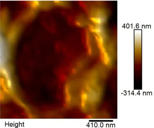
Figure 2. Surface variations of microcapsules. Top-view AFM (a) topographic image, (b) elastic modulus and (c) deformation of (1) h-MPCMs, (2) h-MPCMs after removal of eicosane and (3) s-MPCMs. Scale bar: 200 nm.
Figure 3. Quantitative investigation of mechanical properties of h- and s-MPCMs. (a) Deformation and (b) elastic modulus of h-MPCMs microcapsules, washed h-MPCMs microcapsules, s-MPCMs microcapsules and eicosane microcrystals. (c) Schematic diagram of AFM tip probing the h- and s-MPCMs microcapsules.
Figure 4. Heating performance of h- and s-MPCMs. (a) DSC curves of the eicosane, h-MPCMs and s-h-MPCMs at the second endothermic and exothermic cycle. (b) Plot of encapsulation efficiency against capsule shell thickness for the shape-stable MPCMs in (a) and from literature results (red and black dots) (Table S2). Red: Eicosane@? means eicosane core is stabilized by non-nanocarbon shell materials, and black: ?@nanocarbons is for the nanocarbon-stabilized PCM other than eicosane. (c) A collection of DSC curves of the h-MPCMs tested at 5th, 50th and 100th cycles, showing the stable encapsulation during endothermic and exothermic processes. (d) and (e) are SEM images of h- and s-MPCMs after the endothermic and exothermic cycles. Scale bar: 1 µm.
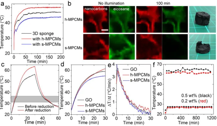
Figure 5. Geometry-dependent overall performance of solar-thermal conversion systems incorporating h- and s-MPCMs. (a) Averaged time-course of the output temperature of the 3D sponges under the simulated solar light irradiation at ~420 W/m2. (b) Left: confocal raman images of 3D graphene-based sponges incorporating h-MPCMs or s-MPCMs before illumination. Red: nanocarbons; green: eicosane. Scale bar: 10 µm. Middle: the images of the same detection positions after 100 min illumination. Right: photographs of the graphene-based sponges respectively incorporating h-MPCMs and s-MPCMs after 100 min illumination. (c) Time-dependant (30 min on, 30 min off) temperature variations of solar energy collecting slurries containing 0.5 wt% h-MPCMs before or after reductions. (d) Comparison in time-dependant temperature variations of slurries containing chemically reduced 0.2 wt% h-MPCMs, s-MPCMs and GO and (e) comparison in corresponding heating rates. (f) Records of maximum and minimum temperatures of slurries containing 0.2 and 0.5 wt% reduced h-MPCMs microcapsules during 20 irradiation on/off cycles.
ASSOCIATED CONTENT
Supporting Information. Cross-section of an h-MPCMs microcapsule microcapsule, TG curves of microcapsules before and after reduction, TEM images of a washed h-MPCMs, list of weight ratio, solid density and volumetric ratio of composing elements in h-MPCMs, XRD patterns from the microcapsules, list of examples of shape-stable MPCMs from the literature, and their fusion heats and diameters, SEM of the 3D sponges, XPS of the reduced h-MPCMs and optical microscope images of h-MPCMs microcapsules before and after multiple photothermal cycles are supplied as Supporting Information. This material is available free of charge via the Internet at http://pubs.acs.org.
AUTHOR INFORMATION
Corresponding Author: Z. Zheng and D. Shchukin: [email protected] and
[email protected] AUTHOR CONTRIBUTIONS
Z. Z. conceived and performed the all the experiments, interpreted the data and wrote the manuscript; Z. C., Z. L. and R. A. contributed the PF-QNM-AFM experiments; G.-K. X. helped calculations based on the AFM results A. H. supported with freeze drying processes; F. M. and R. R. supported with the XPS measurements; M. M. contributed the XRD experiment; W. L. helped with photothermal experiments; D. S. supervised the complementation of the project.
ACKNOWLEDGMENT
Z. Z. and D.S. thank the support of ERC Consolidator Grants (ERC 647969) “Nanoencapsulation for Energy Storage and Controlled Release” (ENERCAPSULE).
REFERENCES
(1) Weinstein, L. A.; Loomis, J.; Bhatia, B.; Bierman, D. M.; Wang, E. N.; Chen, G. Concentrating Solar Power. Chem. Rev. 2015, 115, 12797―12838.
(2) Zhang, L.; Tang, B.; Wu, J.; Li, R.; Wang, P. Hydrophobic Light-to-Heat Conversion Membranes with Self-Healing Ability for Interfacial Solar Heating. Adv. Mater. 2015, 27, 4889―4894.
(3) Ni, G.; Miljkovic, N.; Ghasemi, H.; Huang, X.; Boriskina, S. V.; Lin, C.-T.; Wang, J.; Xu, Y.; Rahman, M. M.; Zhang, T.; Chen, G. Volumetric Solar Heating of Nanofluids for Direct Vapor Generation. Nano Energy 2015, 17, 290―301.
(4) Ghasemi, H.; Ni, G.; Marconnet, A. M.; Loomis, J.; Yerci, S.; Miljkovic, N.; Chen, G. Solar Steam Generation by Heat Localization. Nat. Commun. 2014, 5, 4449―4456.
(5) Han, S.; Wu, D. Q.; Li, S.; Zhang, F.; Feng, X. L. Porous Graphene Materials for Advanced Electrochemical Energy Storage and Conversion Devices. Adv. Mater. 2014, 26, 849―864.
(6) Yang, X. W.; Cheng, C.; Wang, Y. F.; Qiu, L.; Li, D. Liquid-Mediated Dense Integration of Graphene Materials for Compact Capacitive Energy Storage. Science 2013, 341, 534―537. (7) Chen, L. J.; Zou, R. Q.; Xia, W.; Liu, Z. P.; Shang, Y. Y.; Zhu, J. L.; Wang, Y. X.; Lin, J. H.; Xia, D. G.; Cao, A. Y. Electro- and Photodriven Phase Change Composites Based on Wax-Infiltrated Carbon Nanotube Sponges. ACS Nano 2012, 6, 10884―10892.
(8) Zhu, Y. L.; Liang, S.; Wang, H.; Zhang, K.; Jia, X. R.; Tian, C. R.; Zhou, Y. L.; Wang, J. H. Morphological Control and Thermal Properties of Nanoencapsulated n-Octadecane Phase
Change Material with Organosilica Shell Materials. Energ. Convers. Manage. 2016, 119, 151―162.
(9) Do, T.; Ko, Y. G.; Chun, Y.; Choi, U. S. Encapsulation of Phase Change Material with Water-Absorbable Shell for Thermal Energy Storage. ACS Sust. Chem. Eng. 2015, 3, 2874―2881.
(10) Jamekhorshid, A.; Sadrameli, S. M.; Farid, M. A Review of Microencapsulation Methods of Phase Change Materials (PCMs) As A Thermal Energy Storage (TES) Medium. Renew. Sust. Energ. Rev. 2014, 31, 531―542.
(11) Ge, H. S.; Li, H. Y.; Mei, S. F.; Liu, J. Low Melting Point Liquid Metal As A New Class of Phase Change Material: An Emerging Frontier in Energy Area. Renew. Sust. Energ. Rev.
2013, 21, 331―346.
(12) Li, B.; Liu, T.; Hu, L.; Wang, Y.; Gao, L. Fabrication and Properties of Microencapsulated Paraffin@SiO2 Phase Change Composite for Thermal Energy Storage. ACS Sust. Chem. Eng. 2013, 1, 374―380.
(13) Alkan, C.; Sarı, A.; Karaipekli, A. Preparation, Thermal Properties and Thermal Reliability of Microencapsulated n-Eicosane As Novel Phase Change Material for Thermal Energy Storage. Energ. Convers. Manage. 2011, 52, 687―692.
(14) Ye, S. B.; Zhang, Q. L.; Hu, D. D.; Feng, J. C. Core-Shell-like Structured Graphene Aerogel Encapsulating Paraffin: Shape-Stable Phase Change Material for Thermal Energy Storage. J. Mater. Chem. A 2015, 3, 4018―4025.
(15) Sun, H. Y.; Xu, Z.; Gao, C. Multifunctional, Ultra-Flyweight, Synergistically Assembled Carbon Aerogels. Adv. Mater. 2013, 25, 2554―2560.
(16) Zheng, Z.; Jin, J.; Xu, G.-K.; Zou, J.; Wais, U.; Beckett, A.; Heil, T.; Higgins, S.; Guan, L.; Wang, Y.; Shchukin, D. Highly Stable and Conductive Microcapsules for Enhancement of Joule Heating Performance. ACS Nano 2016, 10, 4695―4703.
(17) Yuan, K. J.; Wang, H. C.; Liu, J.; Fang, X. M.; Zhang, Z. G. Novel Slurry Containing Graphene Oxide-Grafted Microencapsulated Phase Change Material with Enhanced Thermo-Physical Properties and Photo-Thermal Performance. Sol. Energ. Mat. Sol. C 2015, 143, 29―37. (18) Hyun, D. C.; Levinson, N. S.; Jeong, U.; Xia, Y. Emerging Applications of Phase-Change Materials (PCMs): Teaching an Old Dog New Tricks. Angew. Chem., Int. Ed. 2014, 53, 3780-3795.
(19) Sahoo, S. K.; Das, M. K.; Rath, P. Application of TCE-PCM Based Heat Sinks for Cooling of Electronic Components: A Review. Renew. Sust. Energ. Rev. 2016, 59, 550―582. (20) Wang, Y.; Chen, Z. Q.; Ling, X. A Molecular Dynamics Study of Nano-Encapsulated Phase Change Material Slurry. Appl. Therm. Eng. 2016, 98, 835―840.
(21) Vélez, C.; Khayet, M.; Ortiz de Zárate, J. M. Temperature-Dependent Thermal Properties of Solid/Liquid Phase Change EveNumbered Alkanes: Hexadecane, Octadecane and n-Eicosane. Appl. Energ. 2015, 143, 383―394.
(22) Yang, J.; Qi, G. Q.; Tang, L. S.; Bao, R. Y.; Bai, L.; Liu, Z. Y.; Yang, W.; Xie, B. H.; Yang, M. B. Novel Photodriven Composite Phase Change Materials with Bioinspired
Modification of BN for Solar-Thermal Energy Conversion and Storage. J. Mater. Chem. A 2016, 4, 9625―9634.
(23) Huang, X. Y.; Liu, Z. P.; Xia, W.; Zou, R. Q.; Han, R. P. S. Alkylated Phase Change Composites for Thermal Energy Storage Based on Surface-Modified Silica Aerogels. J. Mater. Chem. A 2015, 3, 1935―1940.
(24) Li, Y. Q.; Samad, Y. A.; Polychronopoulou, K.; Alhassan, S. M.; Liao, K. From Biomass to High Performance Solar-Thermal and Electric-Thermal Energy Conversion and Storage Materials. J. Mater. Chem. A 2014, 2, 7759―7765.
(25) Huang, X. Y.; Xia, W.; Zou, R. Q. Nanoconfinement of Phase Change Materials within Carbon Aerogels: Phase Transition Behaviors and Photo-to-Thermal Energy Storage. J. Mater. Chem. A 2014, 2, 19963―19968.
(26) Liu, Z. P.; Zou, R. Q.; Lin, Z. Q.; Gui, X. C.; Chen, R. J.; Lin, J. H.; Shang, Y. Y.; Cao, A. Y. Tailoring Carbon Nanotube Density for Modulating Electro-to-Heat Conversion in Phase Change Composites. Nano Lett. 2013, 13, 4028―4035.
(27) Wang, Y. M.; Tang, B. T.; Zhang, S. F. Single-Walled Carbon Nanotube/Phase Change Material Composites: Sunlight-Driven, Reversible, Form-Stable Phase Transitions for Solar Thermal Energy Storage. Adv. Funct. Mater. 2013, 23, 4354―4360.
(28) Chen, L.; Zou, R.; Xia, W.; Liu, Z.; Shang, Y.; Zhu, J.; Wang, Y.; Lin, J.; Xia, D.; Cao, A. Electro- and Photodriven Phase Change Composites Based on Wax-Infiltrated Carbon Nanotube Sponges. ACS Nano 2012, 6, 10884―10892.
(29) Bae, J. J.; Lim, S. C.; Han, G. H.; Jo, Y. W.; Doung, D. L.; Kim, E. S.; Chae, S. J.; Huy, T. Q.; Luan, N. V.; Lee, Y. H. Heat Dissipation of Transparent Graphene Defoggers. Adv. Funct. Mater. 2012, 22, 4819―4826.
(30) Su, Y.; Liu, G.; Xie, B.; Fu, D.; Wang, D. Crystallization Features of Normal Alkanes in Confined Geometry. Acc. Chem. Res. 2014, 47, 192―201.
(31) De Castro, P. F.; Ahmed, A.; Shchukin, D. G. Confined-Volume Effect on the Thermal Properties of Encapsulated Phase Change Materials for Thermal Energy Storage. Chem.-Eur. J.
2016, 22, 4389―4394.
(32) Phadungphatthanakoon, S.; Poompradub, S.; Wanichwecharungruang, S. P. Increasing the Thermal Storage Capacity of a Phase Change Material by Encapsulation: Preparation and Application in Natural Rubber. ACS Appl. Mater. Interfaces 2011, 3, 3691―3696.
(33) Tarakeshwar, P.; Choi, H. S.; Kim, K. S. Olefinic vs Aromatic π−H Interaction: A Theoretical Investigation of the Nature of Interaction of First-row Hydrides with Ethene and Benzene. J. Am. Chem. Soc. 2001, 123, 3323―3331.
(34) Tsuzuki, S.; Honda, K.; Uchimaru, T.; Mikami, M.; Tanabe, K. Origin of the Attraction and Directionality of the NH/π Interaction: Comparison with OH/π and CH/π Interactions. J. Am. Chem. Soc. 2000, 122, 11450―11458.
(35) Nishio, M.; Hirota, M. Ch-Pi-Interaction - Implications in Organic-Chemistry. Tetrahedron 1989, 45, 7201―7245.
(36) Delgado, M.; Lazaro, A.; Mazo, J.; Zalba, B. Review on Phase Change Material Emulsions and Microencapsulated Phase Change Material Slurries: Materials, Heat Transfer Studies and Applications. Renew. Sust. Energ. Rev. 2012, 16, 253―273.
(37) Sharma, A.; Tyagi, V. V.; Chen, C. R.; Buddhi, D. Review on Thermal Energy Storage with Phase Change Materials and Applications. Renew. Sust. Energ. Rev. 2009, 13, 318―345. (38) Osserman, R. The Isoperimetric Inequality. Bull. Amer. Math. Soc. 1978, 56, 1128―1238.
(39) Denkov, N.; Tcholakova, S.; Lesov, I.; Cholakova, D.; Smoukov, S. K. Self-Shaping of Oil Droplets via The Formation of Intermediate Rotator Phases upon Cooling. Nature 2015, 528, 392―395.
(40) Denkov, N.; Cholakova, D.; Tcholakova, S.; Smoukov, S. K. On the Mechanism of Drop Self-Shaping in Cooled Emulsions. Langmuir 2016, 32, 7985―7991.
(41) Ganguly, A.; Sharma, S.; Papakonstantinou, P.; Hamilton, J. Probing the Thermal Deoxygenation of Graphene Oxide Using High-Resolution In Situ X-ray-Based Spectroscopies. J. Phys. Chem. C 2011, 115, 17009―17019.
(42) Senthilnathan, J.; Liu, Y.-F.; Rao, K. S.; Yoshimura, M. Submerged Liquid Plasma for the Synchronized Reduction and Functionalization of Graphene Oxide. Sci. Rep. 2014, 4, 4395―4402.
(43) Picas, L.; Rico, F.; Deforet, M.; Scheuring, S. Structural and Mechanical Heterogeneity of the Erythrocyte Membrane Reveals Hallmarks of Membrane Stability. ACS Nano 2013, 7, 1054―1063.
(44) Zheng, R.; Gao, J.; Wang, J.; Chen, G. Reversible Temperature Regulation of Electrical and Thermal Conductivity Using Liquid–Solid Phase Transitions. Nat. Commun. 2011, 2, 289―297.
(45) Kashyap, K. T.; Koppad, P. G.; Puneeth, K. B.; Aniruddha Ram, H. R.; Mallikarjuna, H. M. Elastic Modulus of Multiwalled Carbon Nanotubes Reinforced Aluminum Matrix Nanocomposite – A Theoretical Approach. Comp. Mater. Sci. 2011, 50, 2493―2495.
(46) Gunther, E.; Mehling, H.; Hiebler, S. Modeling of Subcooling and Solidification of Phase Change Materials. Model. Simul. Mater. Sc. 2007, 15, 879―892.
(47) Huxtable, S. T.; Cahill, D. G.; Shenogin, S.; Xue, L.; Ozisik, R.; Barone, P.; Usrey, M.; Strano, M. S.; Siddons, G.; Shim, M.; Keblinski, P. Interfacial Heat Flow in Carbon Nanotube Suspensions. Nat. Mater. 2003, 2, 731―734.
(48) Xu, X.; Zhang, Q.; Yu, Y.; Chen, W.; Hu, H.; Li, H. Naturally Dried Graphene Aerogels with Superelasticity and Tunable Poisson's Ratio. Adv. Mater. 2016, 28, 9223―9230.
(49) Mei, X. G.; Ouyang, J. Y. Ultrasonication-Assisted Ultrafast Reduction of Graphene Oxide by Zinc Powder at Room Temperature. Carbon 2011, 49, 5389―5397.
Supporting Information For
Microencapsulated Phase Change Materials in
Solar-Thermal Conversion Systems: Understanding
Geometry-Dependent Heating Efficiency and
System Reliability
Zhaoliang Zheng†, *, Zhuo Chang‡, Guang-Kui Xu§, Fiona McBride||, Alexandra Ho†, Zhuola
Zhuola‡, Marios Michailidis†, Wei Li¶, Rasmita Raval||, Riaz Akhtar‡ and Dmitry Shchukin†,*
†
Stephenson Institute for Renewable Energy, Department of Chemistry, University of Liverpool, Crown Street, Liverpool, L69 7ZD, UK.
‡
Centre for Materials and Structures, School of Engineering, University of Liverpool, Liverpool, L69 3GH, UK.
§
International Center for Applied Mechanics, State Key Laboratory for Strength and Vibration of Mechanical Structures, Xi'an Jiaotong University, Xi'an, 710049, China.
||
Surface Science Research Centre, University of Liverpool, Liverpool L69 3BX, UK.
¶
Chemical Engineering & Applied Chemistry, European Bioenergy Research Institute and Aston Materials Centre, Aston University, Birmingham, B4 7ET, UK.
SUPPORTING INFORMATION CONTENTS MATERIALS
COMPLEMENTARY METHODS
Figure S1: Cross-section of an h-MPCMs microcapsule is shown.
Figure S2: Concentrations of eicosane and nanocarbons are determined with TG. Figure S3: The thickness of microcapsule shell is obtained based on TEM images. Figure S4: Deflated nanocarbon shell wrapping an eicosane microcrystal for s-MPCMs.
Table S1. Weight ratio, solid density and volumetric ratio of composing elements in h-MPCMs. Figure S5. XRD spectra confirm the good crystallinity of h-MPCMs.
Table S2. Examples of shape-stable MPCMs from the literature, and their fusion heats and diameters.
Figure S6. The incorportation has little influence on the fluffy structures, as confirmed with SEM.
Figure S7. Pure graphene-based sponge has no fusion heat as revealed with DSC. Figure S8. The h-MPCMs can maintain the equilibrium output temperature around PCR Figure S9. Reduction of h-MPCMs is confirmed by XPS.
Figure S10. TG curves reveal the retention of PCMs in h-MPCMs and severer loss from s-MPCMs.
MATERIALS
GO solution (4 mg/mL, 777676-200ML), multi-walled CNT (698849-1G), hydrazine hydrate (225819-500ML) and dodecylbenzenesulfonic acid (44198-250ML) was obtained from Sigma-Aldrich, and used as received.
COMPLEMENTARY METHODS
Electron microscopy. Scanning electron microscope (SEM) analysis was conducted using a JSM-7001F Scanning Electron Microscope from JEOL. To get the cross-sections of microcapsules, a film of microcapsules was made by filtrating the cooled emulsions, followed by complete drying in vacuum and cutting with a sharp blade. Microcapsules investigated by transmission electron microscopy (TEM) was made by removing the MPCMs. A JEOL 2100FCs with a Schottky Field Emission Gun was run with 200 kV accelerating voltage.
Solid content analysis. A Helium Pycnometer (Micromeritics AccuPyc II 1340) was used to measure the skeletal volume of film stacked with microcapsules, which can be employed to assess the density and in turn the connected porosity of materials.
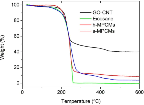
Figure S2. TG curves of nanocarbon capsule materials, eicosane, h-MPCMs and s-MPCMs. On the basis of residue nanocarbons (40 wt%), eicosane (~ 0), h-MPCMs (10 wt%) and s-MPCMs (5 wt%) samples, the mass content of eicosane in h- and s-MPCMs can be calculated to be 75 and 87.5 wt%, respectively.
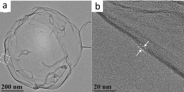
Figure S3. (a) TEM and (b) HRTEM image of a h-MPCMs microcapsule after removal of eicosane. The thickness of GO sheets is around 4.5 nm and the diameter of a multi-wall CNT is around 6-13 nm, thus making the thickness of the h-MPCMs microcapsule 4.5 to 17.5 nm.
Figure S4. AFM topographic image of s-MPCMs microcapsules, exhibiting a smooth surface and deflated capsules.
Table S1. Weight ratio, solid density and volumetric ratio of composing elements in h-MPCMs. eicosane
GO CNT Nanocarbons Solid phase homogeneous interacted
wt%a) 75 24.5 0.5 25 100
ρ (g/cm3) 0.79 1.9 1.4 ― ―
vol% 17.29 0.25b) 2.4 0.06 2.46 20
a)
Determined by TGA. b) The volume of eicosane interacting with adjacent GO and CNT is 11% and 18% of that of these two nanocarbon materials in h-MPCMs.
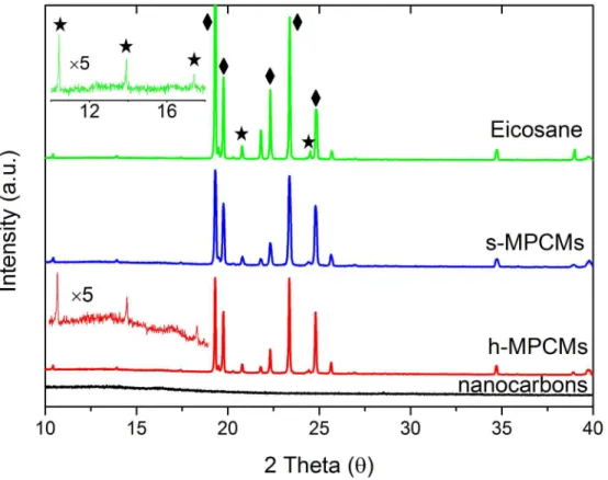
Figure S5. XRD spectra of nanocarbon capsule materials, eicosane, h-MPCMs and s-MPCMs. It shows that h-MPCMs and s-MPCMs resemble the bulk C20 in crystallinity (triclinic phase, P-l, rhombus). Furthermore, the well-preserved (00l) faces (stars) reveals the retention of free rotation along the backbone of the molecules.1 Meanwhile, a weak and broad peak of h-MPCMs at the lower diffraction degrees reveals the capsule shell is made of few layers of GO-CNT hybridized sheets.2
Table S2. Information from examples of shape-stable MPCMs in the literatures.
Mark Shell material Core material Diameter Encapsulation ratio Ref. Mesoporous and Nanoporous silica eicosane 15 nm 12.25% 3 Polymethylmethacrylate PMMA eicosane 700 nm 35% 4 Polyurea eicosane 75% 5 Urea–melamine– formaldehyde eicosane 0.6-1.1 µm 71% 6 PVDF composite nanofibers eicosane 35-172 nm 32.49wt% 7 P(MMA-co-AA) eicosane 22.53 µm 32.9% 8
Silica nanoparticles eicosane 1.5-2 µm 32.97 9
silk fibroin (SF) and chitosan (CHI)
eicosane 8-38 µm 45.7 wt %. 10 Melamine-formaldehyde eicosane 0.5-2.7 µm 76 11 Urea-formaldehyde eicosane 79 µm 60.2% 12 GO modified with Adipic acid and
diethanolamine
n-hexadecane 20-30 µm 78.5% 13
GO modified with silica paraffin 20 um 49.6% 14
Figure S6. SEM images of 3D graphene-based photothermal sponges containing 5 % of (a) h-, (b) s-MPCMs, and (c) pure graphene-based sponges. The incorportation has little influence on the fluffy structures.
Figure S7. DSC curves of the 3D sponge with h-MPCMs microcapsules and without MPCMs at the 2nd endothermic and exothermic cycle. The control sample has no characteristic endothermic and exothermic peaks.
Figure S8. Time-course of the output temperature of the 3D sponges under the simulated solar light irradiation at ~200 W/m2.
Figure S9. XPS spectrum of h-MPCMs microcapsules after ultrasound-assisted reduction. The C/O ratio increased from 3 to ~ 5 after reduction, as compared with Figure 1h. The C 1s spectra shown the dominant role of sharp C-C sp2 peak, indicating the trend towards a more graphene like character in the sample. The π-π* shakeup satellite peak also observed for the reduced sample additionally indicates the presence of aromatic carbons.16
Figure S10. TG curves of h- and s-MPCMs microcapsules after sonication-assisted reductions. After ultrasound-assisted reduction, the reduced h-MPCMs microcapsules maintain the sharp weight loss range from 200 to 260 °C, and increase the calcination residue to ∼23% due to the elimination of oxygen from GO sheets (Figure S7). The result reflects that h-MPCMs remain stable encapsulation after the ultrasound-assisted reduction; while, the delayed decomposition for reduced s-MPCMs microcapsules and the notably increased residue (∼50%) indicate a severe loss of eicosane from the sample.
Figure S11. Image of reduced h-MPCMs microcapsules before and after photothermal cycles.
a
b
REFERENCE
(1) Sirota, E. B.; King, H. E.; Singer, D. M.; Shao, H. H. Rotator Phases of the Normal Alkanes - an X-Ray-Scattering Study. J. Chem. Phys. 1993, 98, 5809―5824.
(2) Wang, S.; Zhang, Y.; Abidi, N.; Cabrales, L. Wettability and Surface Free Energy of Graphene Films. Langmuir 2009, 25, 11078―11081.
(3) Wang, W.; Wang, C.; Li, W.; Fan, X.; Wu, Z.; Zheng, J.; Li, X., Novel Phase Change Behavior of n-Eicosane in Nanoporous Silica: Emulsion Template Preparation and Structure Characterization Using Small Angle X-ray Scattering. Phys. Chem. Chem. Phys. 2013, 15, 14390―14395.
(4) Alkan, C.; Sarı, A.; Karaipekli, A., Preparation, Thermal Properties and Thermal Reliability of Microencapsulated n-Eicosane as Novel Phase Change Material for Thermal Energy Storage. Energ. Convers. Manag. 2011, 52, 687―692.
(5) Lan, X. Z.; Tan, Z. C.; Zou, G. L.; Sun, L. X.; Zhang, T., Microencapsulation of n-Eicosane as Energy Storage Material. Chinese J. Chem. 2004, 22, 411―414.
(6) Zhang, X. X.; Fan, Y. F.; Tao, X. M.; Yick, K. L., Crystallization and Prevention of Supercooling of Microencapsulated n-Alkanes. J. Colloid Interf. Sci. 2005, 281, 299―306. (7) Do, C. V.; Nguyen, T. T. T.; Park, J. S., Phase-Change Core/Shell Structured Nanofibers Based on Eicosane/Poly(vinylidene fluoride) for Thermal Storage Applications. Korean J. Chem.
Eng. 2013, 30, 1403―1409.
(8) Alkan, C.; Aksoy, S. A.; Anayurt, R. A., Synthesis of Poly(methyl methacrylate-co-acrylic acid)/n-Eicosane Microcapsules for Thermal Comfort in Textiles. Text. Res. J. 2015. 4, 1―8.
(9) He, F.; Wang, X.; Wu, D., Phase-Change Characteristics and Thermal Performance of Form-Stable n-Alkanes/Silica Composite Phase Change Materials Fabricated by Sodium Silicate Precursor. Renew. Energ. 2015, 74, 689―698.
(10) Basal, G.; Sirin Deveci, S.; Yalcin, D.; Bayraktar, O., Properties of n-Eicosane-Loaded Silk Fibroin-Chitosan Microcapsules. J. Appl. Polym. Sci. 2011, 121, 1885―1889.
(11) Mohaddes, F.; Islam, S.; Shanks, R.; Fergusson, M.; Wang, L.; Padhye, R., Modification and Evaluation of Thermal Properties of Melamine-Formaldehyde/n-Eicosane Microcapsules for Thermo-Regulation Applications. Appl. Therm. Eng. 2014, 71, 11―15.
(12) Tseng, Y. H.; Fang, M. H.; Tsai, P. S.; Yang, Y. M., Preparation of Microencapsulated Phase-Change Materials (MCPCMs) by Means of Interfacial Polycondensation. J.
Microencapsul. 2005, 22, 37―46.
(13) Zhang, Y.; Zheng, X. H.; Wang, H. T.; Du, Q. G., Encapsulated Phase Change Materials Stabilized by Modified Graphene Oxide. J. Mater. Chem A 2014, 2, 5304―5314.
(14) Yuan, K. J.; Wang, H. C.; Liu, J.; Fang, X. M.; Zhang, Z. G., Novel Slurry Containing Graphene Oxide-Grafted Microencapsulated Phase Change Material With Enhanced Thermo-Physical Properties and Photo-Thermal Performance. Sol. Energ. Mat. Sol. C 2015, 143, 29―37. (15) Dao, T. D.; Jeong, H. M., A Pickering Emulsion Route to A Stearic Acid/Graphene Core-Shell Composite Phase Change Material. Carbon 2016, 99, 49―57.
(16) Ganguly, A.; Sharma, S.; Papakonstantinou, P.; Hamilton, J., Probing the Thermal Deoxygenation of Graphene Oxide Using High-Resolution In Situ X-ray-Based