Rapid Prototyping of Application-Specific
Signal Processors (RASSP) In-Progress Report
by James E. Saultz
Lockheed Martin Advanced Technology Laboratories 1 Federal Street, A&E Building, 3W
Camden, NJ 08102
Abstract
The goal of the DARPA/Tri-Service-sponsored Rapid Prototyping of Application-Specific Signal Processors (RASSP) program is to reduce the cost and time to develop and manufacture sig-nal processors by at least a factor of four. Lockheed Martin Advanced Technology
Laboratories’ (ATL) approach to reaching this goal is based on three thrusts: methodology, model-year architecture, and infrastructure (enterprise). The Advanced Technology
Laboratories’ RASSP team — composed of an alliance of companies — implemented the first baseline RASSP system, which advances today’s state-of-the-art by a factor of >2X. The Advanced Technology Laboratories’ RASSP used the methodology and tools to demonstrate cost and design-cycle improvements on the benchmark virtual prototype, and developed a hardware/ software system that demonstrated first-pass success. Additional developments underway will provide further benefits and will demonstrate 4X improvements in cost and time to market. This paper updates the team’s progress halfway through the program, and highlights the impact of using the RASSP concepts on the design of a SAR processor, a Navy standard processor upgrade, and a CNI application.
Biography
Mr. Saultz has a BSEE from the University of West Virginia and an MSEE from the University of Pennsylvania. He has worked continuously in the RCA, GE Aerospace, Martin Marietta, and Lockheed Martin organizations from 1958 until the present in engineering, program manage-ment, and business development. His experience ranges from the design and development of signal processors, VLSI, and CAD tools to program managing the RCA Microelectronics
Center’s VLSI fabrication facility. As the Program Director for ATL’s RASSP program, Mr. Saultz oversees the program and directs 25 subcontractors developing RASSP technologies.
1. Introduction
The Rapid Prototyping of Application-Specific Signal Processors (RASSP) program is a
DARPA/Tri-Service initiative that is dramatically improving how signal processors are designed, manufactured, upgraded, and supported. A major program goal is to reduce by at least a factor of four the time to take a design from concept to fielded prototype. The Lockheed Martin Advanced Technology Laboratories (ATL) RASSP program approach to reaching the program goal is based on implementing three technology thrusts: methodology, model-year architec-ture, and infrastructure (enterprise).
The methodology is based on a concurrent/collaborative hardware/software codesign approach that embraces the full design hierarchy, from requirements to manufacturing product data
descriptions [1]. The model-year architecture focuses on leveraging COTS technology, coupled with designing flexible, functional interfaces to enable regular, low-cost technology upgrades. The infrastructure enables the methodology and model-year architecture to work across multi-discipline, concurrent-engineering teams by providing integrated workflows, data, and network services. The resulting functionality is a much greater capability than the sum of its parts, and it enables the concurrent/collaborative virtual corporation of the future.
This paper highlights the design systems the ATL team implemented and describes how these systems support the goal of improving the process by a factor of 4. Sections 2 through 4 describe the three elements of the RASSP technology triad: methodology, model-year archi-tecture, and Infrastructure, respectively. The infrastructure discussion in Section 4 details both the integrated RASSP design environment, which provides the tools needed to support rapid prototyping, and the enterprise system, which enables collaborative design through its inte-grated process, tool, and information management capabilities. Section 5 describes how far along the ATL RASSP team is on the road to 4X. It also provides several examples of improve-ments demonstrated to date.
2. Methodology
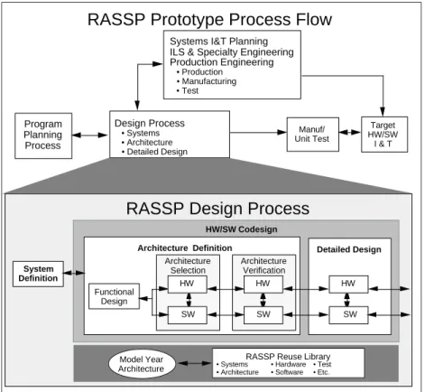
This first element of the RASSP technology triad defines how to develop designs to reduce time-to-market and life-cycle cost by a factor of four. As shown in Figure 1, the methodology process is partitioned as a function of the level of abstraction of the evolving design, not as a function of discipline [2]. The methodology is composed of three major functional processes: the system, architecture, and detailed design processes. Each functional process has associat-ed with it a design-for-test strategy.The result merges hardware and software into a true code-sign process; any distinctions between hardware and soft-ware are made within the spe-cific process. Users imple-ment hardware/ software codesign the initial partitioning of functions to hardware and software elements, all the way to manufacturing release. At each step in the hierarchy, users simulate hardware and software models at equivalent levels of abstraction to verify both functionality and perfor-mance, as shown in another view of the process in Figure 2. Each process area is closely tied to the RASSP vision of an iterative (spiral-like) develop-ment that results in a series of virtual prototypes. Program Planning Process Target HW/SW I & T Manuf/ Unit Test
RASSP Prototype Process Flow
Production Engineering • Production
• Manufacturing • Test
Systems I&T Planning ILS & Specialty Engineering
Design Process • Systems • Architecture • Detailed Design System Definition
RASSP Design Process
HW/SW CodesignArchitecture Definition Detailed Design
SW HW Architecture Selection SW HW Functional Design Architecture Verification SW HW
RASSP Reuse Library Model Year
Architecture • Systems• Architecture • Hardware• Software • Test• Etc.
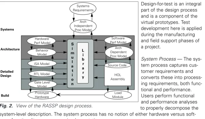
Design-for-test is an integral part of the design process and is a component of the virtual prototypes. Test development here is applied during the manufacturing and field support phases of a project.
System Process — The sys-tem process captures cus-tomer requirements and converts these into process-ing requirements, both func-tional and performance. Users perform functional and performance analyses to properly decompose the system-level description. The system process has no notion of either hardware versus soft-ware functionality or processor implementation.
The first major iterative design cycle results in a requirements specification that has been cap-tured in an appropriate tool for use in the systems requirements review. Users then translate this information into simulatable functions, in what is called an executable specification. The paper by Shaw, et al, in this issue describes executable specifications in more detail. An exe-cutable specification is the first level at which requirements are specified so that users can readi-ly match them to simulators to automaticalreadi-ly verify performance and functionality. In this
process, users allocate processing time to functions, and define functional behavior in the form of algorithms that can be executed. All functions are implementation independent. High-risk items can spawn prototype analysis and development efforts in a mini-spiral, which is a process that allows engineers to take the design to a lower level to help verify the design decision.
Architecture Process — The architecture process transforms processing requirements into a candidate architecture of hardware and software elements. This process, which is the second major cycle of the spiral process, begins the trade-offs between the different processor archi-tecture alternatives. During this process, users allocate the system-level processing require-ments to hardware and/or software functions. Users then verify these functions with each other via “co-verification” at all steps. The architecture process results in a detailed behavioral description of the processor hardware and definition of the software required for each proces-sor in the system. The intent is to verify all code to ensure hardware/software interoperability early in the design process.
The process supports trade-offs by processor behavioral and performance simulations, as well as mixed levels of simulation (algorithm, abstract behavioral, performance, ISA, RTL, etc.) to verify interaction of the hardware and software (see Figure 2). These models are largely com-posed of hierarchical VHDL models of the architecture [3]. Users choose models, to the
maxi-Systems Requirements Arch Independent Proc Model Systems Architecture Detailed Design Build ISA Model RTL Model Gate Level Model Prototype Hardware L i b r a r y S i m u l a t i o n Source Code HOL Assembly Load Module Software Perf Model Arch Dependent Proc Model Hardware Perf Model Behavior Model
mum extent possible, from the model-year architecture elements in the RASSP reuse library. Users develop new required library elements and insert them into the reuse library to support this design phase. The executable specification evolves into a more detailed set of architecture-specific, functional and performance models. Software algorithm implementations are also spe-cific to the candidate architecture(s). Users conduct an architecture design review when they complete architectural trade-offs and verify the design to a high degree of confidence.
The software portion of the architecture process deviates significantly from traditional (func-tional decomposition) approaches. The partitioned software func(func-tionality is broken into three major areas:
1) Algorithm, as specified in a flow graph
2) Scheduling, communications, and execution, as specified by mapping the graph to a specif-ic architecture
3) General command/control software.
The intent on RASSP is to automate these to the maximum extent possible. The ATL team is accomplishing this using a graph-based programming approach(es) that supports correct-by-construction software development based on algorithm- and architecture-specific support library elements [4].
General command/control coding traditionally uses emerging CASE-based code development, documentation, and verification tools. This includes creating new library elements, which are first entered into the system as prototype elements, and then are promoted to verified ele-ments after prototype verification. In the last two years of the RASSP program, the ATL team is focusing on automatically creating signal processing command/control software to the maxi-mum extent possible.
Detailed Design — The third major spiral cycle iteration is the detailed design of software and hardware elements. As with the other processes, users design and verify both hardware and software using a set of detailed functional and performance simulations. At the end of this process, users establish the design, which is a fully verified virtual prototype of the system.
During the hardware portion of the detailed design process, users transform behavioral specifi-cations of the processor into detailed designs (RTL and/or logic-level) by combining hardware partitioning, parts selection, and synthesis. Users functionally verify detailed designs using integrated simulators, and they verify performance/timing to ensure proper performance. The results are detailed hardware layouts and artwork, netlists, and test vectors that can then be seamlessly transitioned to manufacturing and test via format conversion of the data. The entire design package required for release to manufacturing is reviewed at the detailed design review, which is similar to today’s critical design reviews.
Since users verify most of the software developments during the architecture process, soft-ware developments at this point are limited to creating those elements that are target-specific: configuration files, bootstrap and download code, target-specific test code, etc. Users compile and verify all the software (to the extent possible) on the final virtual prototype before the detailed design review. Design release to manufacturing marks the end of the RASSP design process.
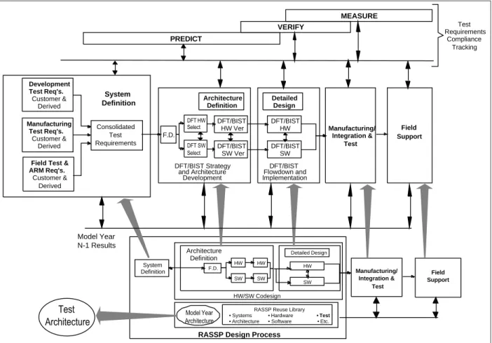
Design-for-test (DFT) — Design-for-test is an integral part of the RASSP methodology [5, 6]. Figure 3 shows the DFT contributions to the project phases defined by the baseline RASSP methodology. The contributions span the project life cycle from design through field deploy-ment. Design-for-test first contributes through a set of consolidated requirements for test that are created by project team members from design, manufacturing, and field support. These representatives create requirements that are quantitative and unambiguous, and they use them to examine and rate candidate architectures. During the architecture selection process, they add DFT hardware and software elements to create a test strategy. Design-for-test also applies functional dependency modeling to indicate early in the process how candidate archi-tectures compare with respect to testability. The representatives then evaluate the emerging test strategy during VHDL verification exercises, implement it during detailed design, and use it during manufacturing and field support.
Requirements consolidation and its subsequent processing result in a singular test philosophy which, as uniformly as possible across all project life-cycle phases, defines an ordered set of test means that measure conformance of the product to the established consolidated require-ments. The result of the singular test philosophy is maximum reuse of test means across all life-cycle phases.
Users select test means by simultaneous creating a test architecture and formal specification of a test strategy in the form of a hierarchy of test strategy diagrams (TSDs). The test
architec-Manufacturing/ Integration & Test Field Support DFT/BIST Flowdown and Implementation Detailed Design DFT/BIST HW DFT/BIST SW DFT/BIST Strategy and Architecture Development Architecture Definition DFT/BIST HW Ver DFT/BIST SW Ver
RASSP Design Process
HW/SW Codesign System Definition Detailed Design HW SW
RASSP Reuse Library • Systems • Hardware • Test
• Architecture • Software • Etc. Architecture Definition HW SW HW SW F.D. Model Year N-1 Results F.D. Manufacturing Test Req's. Customer & Derived Consolidated Test Requirements System Definition
Field Test & ARM Req's. Customer & Derived Development Test Req's. Customer & Derived PREDICT VERIFY MEASURE Test Requirements Compliance Tracking Model Year Architecture Test Architecture Manufacturing/ Integration & Test Field Support DFT HW Select DFT SW Select
ture defines means that are suitable and available to perform necessary tests for a specific project. A wide range of CAD/CAE tools compatible with the RASSP basic design tools sup-port the selection of test means. Test strategy diagrams assign fault coverage, test time, and test cost to the various test means and specify the order of application of test means. Test strategy diagrams track adherence to a standard approach to test: a procedure that detects, isolates, and then corrects faults. Through prediction, verification through simulation, and per-formance measurement, users measure conper-formance to requirements.
A significant result of TSD and test architecture analysis of RASSP Benchmark projects is the pre-eminent role of built-in-self-test (BIST) in signal processing system designs. At component, MCM, and board levels, users can install BIST during product design and testability of a sys-tem, and it can be defined and evaluated before fabrication and final software design. The same BIST selected during the design phase can be used to execute manufacturing tests and can be an effective test means during system field deployment. Efficient BIST can reduce or eliminate the need for expensive Automatic Test Equipment (ATE) during manufacturing by providing built-in-test capability that absorbs a large percentage of the testing and can provide basic testability features in the field where test equipment availability is restricted.
The economic impact of BIST can be very significant for a typical project where design con-sumes only 10% of life-cycle cost. Adding a BIST approach that increases design effort by 20%, adds 2% to the life-cycle cost of a project. The same addition can reduce manufacturing test cost, reduce the number of spares required, reduce the Test Program Set (TPS) re-engineering effort, and potentially reduce life cycle cost by several percent. The RASSP Benchmark 3 project indicates that BIST could potentially reduce life-cycle cost by up to 20%, depending upon the assumption set chosen as the basis for economic analysis. Thus a small expenditure during the design phase can result in a large payback throughout the product life cycle.
Design-for-test improves product performance and reduces cost and time-to-market, primarily from procedural and data reuse across all life-cycle phases. Library grade strategies, proce-dures, BIST software modules, and established component specifications all contribute to a complete approach to testability. In addition, reuse across packaging levels, model-year upgrades and between components/boards at the same packaging level result in further per-formance gains and lower life-cycle costs.
3. Model-Year Architecture
The second element of the RASSP technology triad is the model-year architecture, which defines what users must develop to achieve timely, cost-effective processor prototypes. The ATL RASSP team is developing the model-year architecture, which is more fully described in the paper by Pridmore, et al, in this issue, to promote design upgrades and reuse through standardized, open interfaces, while leveraging state-of-the-art commercial technology devel-opments. RASSP model-year architectures must be supported by library models to facilitate trade-offs and optimizations for specific applications. The hardware and software elements within the library are “encapsulated” by functional wrappers, which add a level of abstraction to hide implementation details and facilitate efficient technology insertion. The notion of model-year upgrades is embodied in reuse libraries and the methodology for their use.
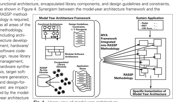
The RASSP program supports the design of architectures through a framework that provides a structured approach to ensure that designs incorporate the following required model-year fea-tures: scalability, heterogeneity, open interfaces, modular software, life-cycle support, testability, and system retrofit [7]. The basic elements that comprise the model-year architecture are the functional architecture, encapsulated library components, and design guidelines and constraints, as shown in Figure 4. Synergism between the model-year architecture framework and the RASSP
method-ology is required, as all areas of the methodology, including archi-tecture develop-ment, hardware/ software code-sign, reuse library management, hardware synthe-sis, target soft-ware generation, and design-for-test are impact-ed by the model-year architecture framework.
4. Infrastructure
The third element of the RASSP technology triad is the Infrastructure, which provides the enabling technology to implement the RASSP process and model-year architecture. The infra-structure is divided into two major elements: the design environment and the enterprise sys-tem. The design environment is a subset of the overall enterprise. It provides the hierarchical, integrated set of tools (described in section 4.1) to support hardware/software codesign and virtual prototyping. The enterprise system, described in Section 4.2, provides the underlying process and data management that enables distributed, collaborative design to occur within an Integrated Product Development Team.
4.1 Design Environment
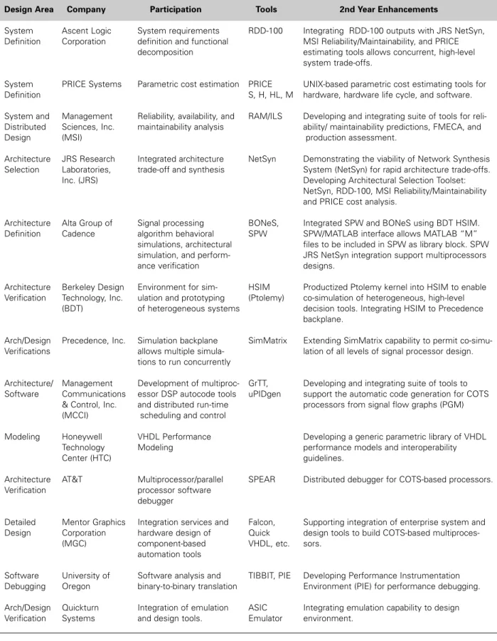
The ATL RASSP Team is developing an integrated, hierarchical set of design automation tools and incorporating it into the overall RASSP enterprise system. These tool developments sup-port the full hierarchical design approach and are keys to achieving the RASSP 4X goals. The tool developments are summarized in Table 1. The following paragraphs describe these RASSP design environment enhancements that go beyond today’s state of the art for the Systems, Architecture, and Software design areas.
System Design Tools — The system definition process is a front-end engineering task that is developing signal processing concepts and performing top-level trade-offs to determine the signal processing subsystem requirements. The ATL team is integrating multi-discipline
capa-Functional Architecture Design Guidelines, Constraints, I / F Standards
Model Year Architecture Framework
Application Notes Encapsulated Library Elements RASSP Re-Use Libraries Modular Software Architecture System Application • Radar • … • IRST • … • UW Acou. • … RASSP Methodology MYA Framework Integrated into RASSP Methodology Specific Instantiation of Model Year Archtecture Fig. 4. Users view of model-year architecture.
Table 1. RASSP tool developments.
Design Area Company Participation Tools 2nd Year Enhancements
System Ascent Logic System requirements RDD-100 Integrating RDD-100 outputs with JRS NetSyn, Definition Corporation definition and functional MSI Reliability/Maintainability, and PRICE
decomposition estimating tools allows concurrent, high-level system trade-offs.
System PRICE Systems Parametric cost estimation PRICE UNIX-based parametric cost estimating tools for Definition S, H, HL, M hardware, hardware life cycle, and software.
System and Management Reliability, availability, and RAM/ILS Developing and integrating suite of tools for reli-Distributed Sciences, Inc. maintainability analysis ability/ maintainability predictions, FMECA, and
Design (MSI) production assessment.
Architecture JRS Research Integrated architecture NetSyn Demonstrating the viability of Network Synthesis Selection Laboratories, trade-off and synthesis System (NetSyn) for rapid architecture trade-offs.
Inc. (JRS) Developing Architectural Selection Toolset:
NetSyn, RDD-100, MSI Reliability/Maintainability and PRICE cost analysis.
Architecture Alta Group of Signal processing BONeS, Integrated SPW and BONeS using BDT HSIM. Definition Cadence algorithm behavioral SPW SPW/MATLAB interface allows MATLAB “M”
simulations, architectural files to be included in SPW as library block. SPW simulation, and perform- JRS NetSyn integration support multiprocessors
ance verification designs.
Architecture Berkeley Design Environment for sim- HSIM Productized Ptolemy kernel into HSIM to enable Verification Technology, Inc. ulation and prototyping (Ptolemy) co-simulation of heterogeneous, high-level
(BDT) of heterogeneous systems decision tools. Integrating HSIM to Precedence backplane.
Arch/Design Precedence, Inc. Simulation backplane SimMatrix Extending SimMatrix capability to permit co-simu-Verifications allows multiple simula- lation of all levels of signal processor design.
tions to run concurrently
Architecture/ Management Development of multiproc- GrTT, Developing and integrating suite of tools to Software Communications essor DSP autocode tools uPIDgen support the automatic code generation for COTS
& Control, Inc. and distributed run-time processors from signal flow graphs (PGM) (MCCI) scheduling and control
Modeling Honeywell VHDL Performance Developing a generic parametric library of VHDL Technology Modeling performance models and interoperability
Center (HTC) guidelines.
Architecture AT&T Multiprocessor/parallel SPEAR Distributed debugger for COTS-based processors. Verification processor software
debugger
Detailed Mentor Graphics Integration services and Falcon, Supporting integration of enterprise system and Design Corporation hardware design of Quick design tools to build COTS-based
multiproces-(MGC) component-based VHDL, etc. sors. automation tools
Software University of Software analysis and TIBBIT, PIE Developing Performance Instrumentation Debugging Oregon binary-to-binary translation Environment (PIE) for performance debugging.
Arch/Design Quickturn Integration of emulation ASIC Integrating emulation capability to design Verification Systems and design tools. Emulator environment.
bilities into a concurrent engineering environment that consists of three major tools: • Ascent Logic’s RDD-100
• Management Sciences’ RAM/ILS toolset
• Lockheed Martin PRICE Systems’ parametric cost estimating tools.
The ATL team uses these tools with other, traditional tools to define the functionality (at the algorithm level) and the performance (at the timeline level) of the signal processing subsys-tem.
The ATL team uses the three major tools tools to: capture and track system engineering requirements; describe the functional behavior of the signal processor; allocate the require-ments to signal processing subsystems; perform high-level reliability and maintainability trade-off analyses; and perform parametric-based cost estimations for the signal processor’s life cycle. Integrating these tools will let system engineers perform high-level trade-off analyses. The ATL RASSP team has developed extensions of Ascent Logic’s requirement capture tool so that is can supply requirements to the Lockheed Martin PRICE and the MSI RAM/ILS tools. The team implemented the PRICE tool to run in a UNIX environment where it can be used to do cost trade-offs. Previously, the PRICE tool had only been available on a PC and was primari-ly a cost anaprimari-lyst tool, as opposed to an engineering design tool.
On the RASSP benchmarks, the team used the combination of requirements capture, para-metric cost estimation, and reliability tools to analyze life-cycle costs. Over the past two years, many users were interested in this capability to do requirements analysis, as well as early sys-tem concept trade-offs. The team is supporting two beta sites using the tools to develop life-cycle cost trade-offs for new products.
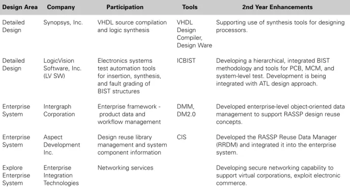
Table 1. RASSP tool developments(cont.).
Design Area Company Participation Tools 2nd Year Enhancements
Detailed Synopsys, Inc. VHDL source compilation VHDL Supporting use of synthesis tools for designing
Design and logic synthesis Design processors.
Compiler, Design Ware
Detailed LogicVision Electronics systems ICBIST Developing a hierarchical, integrated BIST Design Software, Inc. test automation tools methodology and tools for PCB, MCM, and
(LV SW) for insertion, synthesis, system-level test. Development is being and fault grading of integrated with ATL design approach. BIST structures
Enterprise Intergraph Enterprise framework - DMM, Developed enterprise-level object-oriented data System Corporation product data and DM2.0 management to support RASSP design reuse
workflow management concepts.
Enterprise Aspect Design reuse library CIS Developed the RASSP Reuse Data Manager System Development management and system (RRDM) and integrated it into the enterprise
Inc. component information system.
Explore Enterprise Networking services Developing secure networking capability to Enterprise Integration support virtual corporations, exploit electronic
Architecture Design Tools — Meeting RASSP’s time-to-market and reuse goals requires a set of tools to help users partition and map a functional application onto a potentially large number of computing nodes. JRS’ NetSyn tool is the first available tool to help users perform multi-processor hardware/software codesign for architectural trade-offs. The ATL RASSP team is integrating NetSyn with tools from other disciplines to enable designers to perform concurrent engineering trade-offs. The result will enable users to efficiently evaluate varying architecture approaches for a particular application and to generate top-level size, weight, cost, reliability, and performance estimates.
NetSyn will import a set of requirements (for example, size, weight, power, etc.) from RDD-100 that reflect the constraints on the architecture. During architecture selection, users can compare estimates of these parameters with the requirements for various candidate architec-tures. NetSyn can either generate a data flow graph description in the Processing Graph Method (PGM) format of the required signal processing or it can import a PGM graph from other tools (such as Alta’s SPW). Users can develop candidate architectures within NetSyn and map the data flow graph description of the processing to the architecture using automat-ed or manual techniques. Top-level performance simulations support trade-off evaluations among candidate architectures.
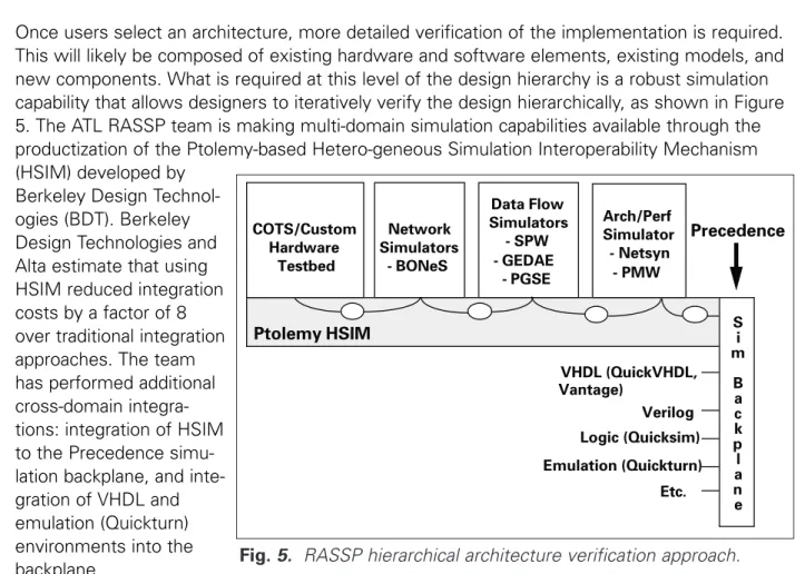
Once users select an architecture, more detailed verification of the implementation is required. This will likely be composed of existing hardware and software elements, existing models, and new components. What is required at this level of the design hierarchy is a robust simulation capability that allows designers to iteratively verify the design hierarchically, as shown in Figure 5. The ATL RASSP team is making multi-domain simulation capabilities available through the productization of the Ptolemy-based Hetero-geneous Simulation Interoperability Mechanism (HSIM) developed by
Berkeley Design Technol-ogies (BDT). Berkeley Design Technologies and Alta estimate that using HSIM reduced integration costs by a factor of 8 over traditional integration approaches. The team has performed additional cross-domain integra-tions: integration of HSIM to the Precedence simu-lation backplane, and inte-gration of VHDL and emulation (Quickturn) environments into the backplane.
Once users select a candidate architecture, they verify it using the architecture verification tools. This tool suite consists of performance and functional simulators at various levels of
COTS/Custom Hardware Testbed Network Simulators - BONeS Data Flow Simulators - SPW - GEDAE - PGSE Arch/Perf Simulator - Netsyn - PMW Ptolemy HSIM Si m B a c k p l a n e Precedence VHDL (QuickVHDL, Vantage) Verilog Logic (Quicksim) Emulation (Quickturn) Etc.
design abstraction (abstract behavior, ISA-level, RTL, etc.) and models of computation (data flow, control flow, event driven, etc.) that users iteratively invoke to hierarchically verify the processor design before detailed implementation. The ATL team will integrate emulation and hardware testbed capabilities into the tools by combining simulation backplane and mixed-level domain (Ptolemy kernel) technologies. The team demonstrated early results of these capabilities by importing MATLAB macros into SPW and coupling the SPW design to the BONeS network simulation.
The ATL team developed a design approach that uses VHDL to convey design information from the initial multiprocessor system concept through synthesizable chip descriptions. The team’s efforts are focused on developing a VHDL performance model interoperability standard to sup-port high-level modeling [8]. The team defined a performance model interoperability standard and developed an example (SAR benchmark) model using this approach. The team distributed models to TRW, JRS, and MIT and demonstrated more than a 100X improvement in simulation time over traditional, ISA-level approaches. Honeywell and ATL are developing readily reconfig-urable generic libraries to support rapid trade-offs. Honeywell, ATL, and Omniview are integrat-ing performance model libraries into a tool — the Performance Model Workbench (PMW) — that will support various design approaches which can be simulated to verify the design.
The Advanced Technology Laboratories’ Graphical Entry Distributed Application Environment (GEDAE) tool supports the development of distributed applications. It provides a workstation environment for application development, tools to support multiprocessor scheduling and mapping, and a run-time environment for efficient execution on hardware testbeds. The Advanced Technology Laboratories is developing a PGM import capability to support the exe-cution and visualization of PGM graphs, and it extended GEDAE’s user interface to help users graphically define candidate architectures. Since hierarchy is inherent in the graphical editor, large, scalable architectures are readily represented as systems made up of interconnected chassis, which are made up of interconnected boards; these boards are made up of intercon-nected processors, memories, and communications elements.
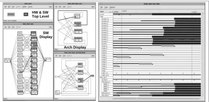
The Advanced Technology Laboratories extended GEDAE’s timeline display to provide an inte-grated hardware/software view during execution, and as a post-execution analysis capability suitable for analysis of performance simulation results. Additional extensions support anima-tion of the playback to present a dynamic correlated view of the applicaanima-tion and the architec-ture activity. This GEDAE extension is called the Architecarchitec-ture Definition/Visualization Tool shown in Figure 6. There is sufficient information in the analysis and animation for users to observe all software activity, processor utilization, and data transfers. The Advanced
Technology Laboratories is integrating the Architecture Definition/Visualization Tool with NetSyn to support the trade-off decision process. The Advanced Technology Laboratories plans to use this same interface for visualizing all levels of the virtual prototyping process, and for target hardware execution timelines.
Software — One of the key ATL RASSP developments is the implementation of a library-based, data-flow-graph-driven autocode process, which abstracts signal processing software generation and maintenance to the graph level. Data flow graphs represent the required signal processing using PGM. This representation is architecture-independent. As users upgrade
hardware, the application description at the graph level remains constant. This approach will support reuse of graph data with model-year upgrades.
The ATL team is implementing a set of autocode generation tools that will enable users to take PGM graphs and automatically generate downloadable code for embedded multiproces-sor environments, as shown in Figure 7. These tools implement the model-year architecture by using the reusable software libraries and targeting the code generation to support the model-year architecture application programming interface (API) and run-time system.
HW & SW Top Level
SW Display
Arch Display
Fig. 6. Example architecture definition/visualization display in GEDAE. (Highlighted boxes and connections indicate execution and communications.)
Target Proc. Primitives
Runtime System
Microkernels, I/O Drivers, etc.
Command
Program Flow Graphs API and App. Libraries
Runtime System
Operating System
Model Year Software Architecture Software Reuse Libraries
Autocode Generator Application Generator Load Image Builder
Software Build Process
Standard Domain Primitives Command Program Processor Architecture … … Partition and Map
Map
…
Set of Executable Programs Algorithm Flow Graph
Connected groups of primitives assigned to the same processor represent graph partitions, which are automatically translated (using the MCCI-developed autocode tools) to source code for the processor type to which the partition has been mapped [4]. This translation uses the optimized math and signal processing libraries for the specified target processor. This enables users to implement fully operational virtual prototypes before final manufacturing release.
Along with the autocode tools, ATL and MCCI completed the design of the RASSP run-time system, which will support management and execution of the autocoded graphs on target hardware. The run-time system is being built with an open interface to operating system microkernels to facilitate porting to commercial products. The first integrated version of the autocode tools and the run-time system have been tested and they will support the Mercury MCOS operating system and Signal processing Application Library (SAL). The autocode tools and run-time system are providing the AN/UYS-2A upgrade program with the ability to easily retarget PGM software to the new hardware, and the ability to upgrade the hardware without modifying the software at the graph level. This effort represents the first real application of automated code generation and run-time support targeted to commercial processors [4]. To date, the initial use of these tools has significantly reduced development time and cost, as described in more detail in Section 5.
4.2 Enterprise System Overview
The RASSP enterprise system architecture is hierarchical. It integrates individual design tools and collections of tools, which are then integrated into specialized frameworks. This architec-ture includes provisions for other (non-design) environments, such as purchasing systems and product data management systems. The architecture also provides a distributed reuse system with an object-oriented repository at the enterprise level and coordinated local framework/tool libraries [9].
The concept of opera-tion for the enterprise framework includes the ability to execute project plans, express-ed as workflows, by teams of engineers. Execution of a work-flow by a member of a design team, as shown in Figure 8, initiates control commands to a CAD/CAE tool as rele-vant for the particular workflow step. This execution also initiates data transactions with the enterprise product
tem; local data management systems; and library systems, as relevant for the particular work-flow step. In addition, the system couples project management tools with the design environ-ment, which receives regular status updates as workflow steps are executed. This process facilitates effective, non-interfering project management.
Users execute the workflows using enterprise methodology management tools, which link to tools, data access mechanisms, and other services. This process allows designers to operate at a higher level of abstraction, allowing them to focus on the real design tasks instead of tool and data management, which significantly improves their productivity.
The enterprise framework provides multiple workspace views for the design environment to support workflow usage. These views include:
• Tool and application workspace
• A data workspace for product and reuse information • Project/workflow workspaces.
The resources, data objects, and applications available to particular engineers are defined by their identity and role in an authorization hierarchy implemented in the enterprise system.
Workflow Management — Workflow management in the RASSP system is comprised of methods and tools to provide the project team with an environment that facilitates day-to-day work. The ATL RASSP team has a process-model-driven philosophy for workflow manage-ment. The detailed representation of the RASSP methodology is modeled using Integration Definition 3 (IDEF3) [10], which is a method to capture and structure process flows [11]. These models are instantiated as workflows in the workflow management tool. The workflow captures:
• Process steps and their precedence relationships
• The personnel roles authorized/required to perform work
• The information objects involved (created, used, modified, destroyed, etc.) in the process step
• The tools to be launched or controlled at each step.
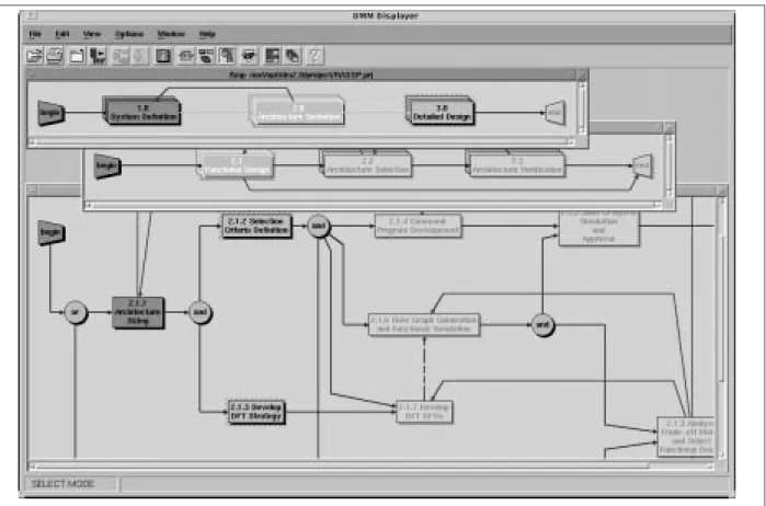
The ATL team is demonstrating the Intergraph Design Methodology Manager (DMM), which graphically represents the workflows of a project (as shown in Figure 9), enforces workflow use, and tracks status of the workflows. Each activity in a workflow may be associated with multiple tools. Users initiate an activity by clicking on the box representing the activity in a workflow; when they exit the activity informs DMM about the status of the activity. The Design Methodology Manager decides whether an activity may be launched or not, based on the sta-tus of the activities that precede it in the workflow. The Design Methodology Manager provides for pre-condition and post-condition scripts of the activities in a workflow. Examples of these activities include functions such as checking for the existence of data objects, or translating data objects to the appropriate formats. This removes these functions as required responsibili-ties for the engineers, thereby enabling significant productivity improvement through increased focus on design tasks. Project engineers or supervisors would normally be responsible for design and implementation of project plans based on workflows using the system.
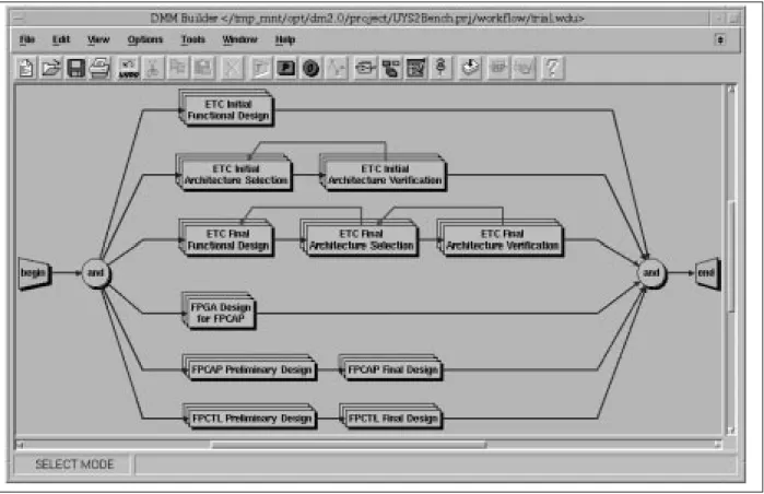
The workflows are hierarchical and they represent the various disciplines associated with elec-tronic design. The workflows consist of reusable workflow segments, which can be combined in various configurations to address specific project needs. Figure 10 shows the workflow for the Benchmark 3 project, which is made up of several reusable workflow segments, such as Architecture Selection and Preliminary Design. These segments consist of multiple process steps, each of which is also reusable. Options available to a user organization are either to make use of the RASSP workflows in current form or to develop process plans based on a combination of reuse of RASSP workflow segments, individual process steps, and possible custom user steps.
The ATL RASSP team developed multiple extensions to the DMM tool: access controls, hierar-chical workflow modeling capability, capability to track status and history of a project, inter-faces to project management tools, and integration with the Enterprise Product Data Manager. The workflow manager also helps capture useful metrics for projects. The metrics being col-lected on the RASSP program include:
• Time spent in a step
• Number of iterations through a path / step • Tool usage
• Person(s) performing the step • Notes per process step. Fig. 9. Graphical workflows.
Manufacturing Interface — The goal of an agile manufacturing environment is to enable the for-mation of virtual organizations and to provide the robust design-for-manufacturing mechanisms that virtual organizations need to develop successful products. To support the ATL RASSP team’s manufacturing interface, the team identified obstacles to first-pass manufacturing suc-cess. Next, the team developed a methodology and an architecture that eliminated these obsta-cles. Because of the critical need for reliable product data exchange, the team incorporated standards such as ISO 10303 and EDIF 400 into the agile manufacturing interface architecture.
The team integrated the manufacturing interface into the RASSP enterprise system, and is being used by the Lockheed Martin Center of Excellence PCA manufacturing facility in Ocala, Florida. The manufacturing interface has processed several PCA designs at this facility, and the data generated was used to produce several missile program PCBs. The results to date reduced manufacturing rework from <15 percent to <5 percent, and reduced design-to-manu-facturing information exchange cycle time from days to hours.
Until recently, transitioning PCA product designs from Lockheed Martin’s design facilities to the manufacturing facility required significant manual data conversion, data reentry, and quality assurance procedures. These manual processes require significant amounts of time to per-form, and they introduced errors and inaccuracies into data generated for production. These data conversion and quality assurance steps took place after a PCA design was considered “complete” and after it was transferred to the manufacturing facility. The current approach passes PCA CAD data directly to the manufacturing facility, thereby eliminating these errors.
Because the manufacturing facility has traditionally not been part of the product design
process, manufacturability issues, such as component placement impact on automation inser-tion equipment, are often present in the data received from design teams. These issues must be resolved. Resolution might require a re-design effort by the team originating the design. Because the cost of design modification is high, if the manufacturability issues are not insur-mountable they may be allowed to remain, even though they increase the recurring engineer-ing cost of product manufacture. These problems have not only contributed to difficulty in achieving first-pass manufacturing success, but unnecessarily increased production difficulties for every production run of each PCA produced.
The ATL manufacturing interface corrects this by enabling virtual partnering between design and manufacturing teams, which makes it easier to collaborate and negotiate between design and manufacturing engineers throughout the product design process.
Several PCA designs have been processed by the manufacturing interface team of SCRA and Lockheed Martin using the RASSP manufacturing interface. The first automated manufactur-ing run of one of these designs yielded 70% functional PCAs, while the other three produced 100% functional PCAs. The first PCA design processed met the objective of first-pass manu-facturing success. The second design processed by the RASSP manumanu-facturing interface had a 70% success rate. The remaining 30% required repair of approximately 2% of their compo-nents. Examination showed that a minor software issue with the RASSP-MI was the cause of the poor yield, and was corrected. On small runs of PCAs, the initial rework can vary from a few percent to 10s of percent depending upon the complexity of the design.
After correcting the RASSP manufacturing interface software issue, two more PCA designs were processed by the SCRA/Lockheed Martin Ocala team using the RASSP manufacturing interface. The manufacturing data produced was used for the first manufacturing run of a batch of PCAs for each design. For these designs, the goal of first-pass manufacturing suc-cess was achieved; none of the PCAs produced required repair. Table 2 summarizes these results.
Table 2.Production results using the RASSP manufacturing interface.
PCA Design PCAs Produced Using PCAs Requiring Repair Success
the RASSP-MI Rate
Design 1 17 0 100%
Design 2 17 5 70.6%
Design 3 17 0 100%
Design 4 17 0 100%
The results obtained using the RASSP manufacturing interface in this industrial setting have confirmed the validity of this approach. By reducing cost and time-to-market, the RASSP man-ufacturing interface is contributing significantly toward meeting the RASSP program’s goals of improved cycle time, quality, and cost. The ATL team is developing an extended version of the RASSP manufacturing interface to support the design and manufacture of complex
electro-mechanical products, further validating the general applicability of the methodology and archi-tecture developed. The team is extending the manufacturing interface capability and will pro-duce EDIF-400 output data that can be directly used with the manufacturing tools.
Information Management — Enterprise information is a key corporate asset that requires a well planned management strategy. The ATL RASSP team developed an enterprise data model that specifies the metadata design engineers and project/system administrators need to track the product and reuse information in the system. To develop the RASSP Enterprise Data Model, the team analyzed several standard models that were multiple sources of product data requirements relative to RASSP-specific requirements. Models analyzed include the Product Data Control Model (developed on the USAF Integrated Data Strategy program) [10], the STEP [12] parts and protocols AP203 [13], and Part 44 [14], which is the standard for prod-uct strprod-ucture configuration.
The team is implementing the enterprise data management system using the Intergraph DM2.0 (Metaphase-based PDM) distributed product data management product [15]. The team is mapping the RASSP enterprise data model to the core model of the DM2.0 product and implementing extensions that make practical and commercial sense, including classes such as security classification, anomaly, product concept, and software configuration item.
The DM2.0 product manages the enterprise documents and their metadata; product structure and configurations; user roles and authorizations; storage locations and vaults; and related data in a distributed environment. It also interfaces with the reuse libraries to enable reuse of the enterprise information. DM2.0 provides these services either directly or under the control of a workflow manager, based on the needs of particular projects. This enables the workflow man-ager to access and store information (such as design documents, bills of material, and test procedures) by process step, as needed.
For configuration management [16] and authorization, RASSP-developed models define specif-ic requirements for these capabilities. Support for implementation of these models is provided using the rules subsystem of DM2.0. A combination of DM2.0 and secure internet services will provide distributed product data management capability for a multi-organization, multi-site environment.
Reuse Management — Library management in the RASSP system supports releasing, cata-loging, and searching of reusable design objects. The RASSP Reuse Data Manager (RRDM) supports this library management. Sources for reusable design objects in the RASSP system include:
• CAD tool libraries
• CAD tool-independent libraries • Component vendor data books
• Design objects created within a design organization
In today’s design environments, the ability of design engineers to maximize reuse is impaired because there is no efficient way for them to search for reusable design objects across
multi-ple sources, and the various sources of reusable data are not coumulti-pled with the design environ-ment. In addition, there are no mechanisms and processes to organize reusable design
objects created within a design organization. Also lacking is an effective way to share reusable design objects within the organization or with other cooperating organizations. The ATL
RASSP team studied the reuse area and defined requirements to guide a new development that will address the problem discussed above.
The RASSP enterprise system includes tools and methods to integrate the various sources of reusable design objects and provide a single source for searching for reusable design data. The enterprise system will enable enterprise-wide sharing of reuse data. The team’s approach to reuse management consists of:
1) Developing a design object class hierarchy, which classifies the various types of design objects in the RASSP domain and models the descriptive data associated with the design objects
2) Developing a commercial library management system, which will implement the design object class hierarchy and provide ways for users to search for design objects across mul-tiple libraries and across a virtual enterprise.
The RASSP reuse management system will support loosely-coupled and tightly-coupled federa-tions of cooperating organizafedera-tions in sharing library data. The team is implementing the core library management search and browse function, which supports the RASSP design object class hierarchy, on top of relational/object database capabilities to provide advanced browsing capabili-ties. An initial version of the reuse class hierarchy is shown in Figure 11. The ATL RASSP team is developing RRDM extensions that support capabilities to manage default and template objects, manage parametric searches, modify existing objects, modify class hierarchy, etc.
5. The Road to 4X
The ATL RASSP team’s general approach to achieving the 4X improvements is to focus on two major areas: improved product quality/productivity, and improved reuse. Improved product quality is provided through the top-down, virtual prototyping process that we have described, and through hardware/software codesign. The combination of these elements leads to a very high percentage of first pass design success. The SAR processor design was completed the first time with only two interconnect corrections required on the PCB, which meant fewer redesign iterations. The integration and test time was reduced from several weeks to a single week. Reuse on the RASSP program is enhanced by the model-year architecture concept and the Reuse Data Management System because the development of the algorithms in a PGM approach supports mapping to another processor approach with minimum additional effort.
Predicting the Improvements — When the elements outlined above are mapped to the tech-nology being developed on RASSP, a roadmap to 4X like that shown in Figure 12 results. The figure maps the process steps to the technology developments that will lead to improved quality and reuse.
To validate the impact of these technology efforts on time-to-market and cost, the ATL RASSP team is developing a three-tiered approach to predicting improvements. At the top level, the spreadsheet-based predictor enables users to map specific programs to the roadmap, and
Fig. 11. The RASSP reuse design object classification hierarchy in the Explore-CIS class browser window.
Fig. 12. General 4X roadmap.
Methodology, tool enhancements, and reuse in front-end design enable big payoffs by minimizing costly back-end tasks
How do we get to 4X payoff?
• Improved quality/process — Top down modeling/virtual
prototype — DFT • Design reuse — Design elements — Components • Productivity
— Individual tool extensions — Tool interoperability
Improved time-to-market enables upgrades through-out product life cycle
Systems Architecture Definition Detailed Design Fab/Test Redesign Integration & Test
Process MYA & Reuse Enterprise System Env. Tool Extensions Tool Integrations Systems Arch. Def. Detailed Design Fab/Test Redesign I & T Process
Reuse & MYA Enterprise
Tool Ext.
Tool Int'g
by Design Phase by RASSP Technology
Two views of Cycle-time Reduction Contributors Road to 4X Model
develop a coarse level of expectation for improvements. The spreadsheet model provides an overall cost/time-to-market prediction that is loosely coupled to more detailed parametric simu-lations.
The team uses parametric simulations to predict the process (schedule) and life cycle costs. Users can simulate the RASSP process, which is captured in IDEF, with several commercial process simulators; AT&T’s WITNESS is the tool used on RASSP, and cost is estimated using the PRICE cost estimation tool. Models that reflect the RASSP process will be available by the end of the program.
The RASSP enterprise system provides real-time schedule and cost information. The system implements the process in the enterprise workflow manager, and provides real-time workflow data linked to project management tools, such as Microsoft Project. Tracking schedule and cost is through automated metric collection in the enterprise system.
Demonstrations to Date— Halfway through the program, the ATL RASSP team has demon-strated a >2X reduction in schedule and development costs on two separate programs. Figure 13 shows a roadmap of these demonstrations mapped to a pre-RASSP program. It shows four demonstration programs, two of which are completed, and one of which is ongoing in two phases (Model Years 1 and 2). The roadmap shows the progression of demonstrations and which elements of RASSP technology the demonstrations are using to attain 4X improve-ments.
The first program was the RASSP Synthetic Aperture Radar (SAR) implementation (BM-1/2) [17, 18]. The team demonstrated a 1.6X overall reduction in time-to-market and development cost when compared to traditional developments. The team achieved first-pass design suc-cess, and the met or exceeded all performance requirements.
The SAR signal processor was composed of a 68040-based host running VxWorks, three Mercury processor boards containing ten i860s, and a high-speed fiber-optic interface board. Originally, the team’s virtual prototype was based on a COTS processor board using the ADSP21060 (SHARC) processor. Performance simulation results from the virtual prototype indicated that six SHARC processors were needed to implement the SAR algorithm. Delay in delivery of the full-function/performance part forced a mid-stream change in the SHARC-based approach, and the team selected a COTS i860-based processor board. In a matter of hours, the team modified the virtual prototype to support the i860 and showed that ten i860 proces-sors were needed. Because the software was captured graphically, it took minutes to reparti-tion and regenerate the code to operate on the i860 processors. System booting and all inter-processor communications was included in the generated code. The initial graph development took about one month. Integration and test of the software on the target signal processor took an additional two weeks. Compared with similar efforts using conventional development tech-niques, this demonstration showed that users can reduce software development time by a minimum of 10X, and reduce integration and test time by 5X using RASSP technology.
The second major demonstration was provided by TRW’s Avionics Systems Division, which is part of the Space & Electronics Group in San Diego, CA. They used the ATL RASSP process to
develop a Spread Spectrum Pre-Processor (SSPP) for the Integrated Sensor Subsystem (ISS) [19]. The SSPP performs Joint Tactical Information Distribution System (JTIDS) pseudo-noise demodulation, MSK demodulation, CCSK demodulation, de-interleave, and Reed-Solomon decoding. The RASSP program directly supported the ISS goals, which were to cut flyaway cost in half, reduce weight and size by two-thirds, and improve reliability by a factor of 3. TRW’s effort on the SSPP began in April 1995 and ended with a transition of models to the ISS program in December 1995. TRW used the RASSP baseline process about one-third of the way through their program. They used MATLAB, SPW, RDD-100, PGSE, NetSyn, and VHDL tools. Preliminary design review material was available for the SSPP in about half the time allocated to the main ISS program; full virtual prototypes were ready by the ISS prelimi-nary design review. To date, TRW has reduced cycle time by approximately a factor of 2, and it appears that it will hold through the end of I&T.
The third major program underway is the UYS-2A upgrade jointly sponsored by the Navy, RASSP, and the DARPA High Performance Scalable Computing (HPSC) program to upgrade the AN/UYS-2A, which is the Navy’s standard signal processor. The program will demonstrate a 15X processing performance improvement over existing implementations at one-third the schedule and cost of the original developments for the first model-year demonstration. Major features include implementation of a 2-GFlop Floating Point Commercial Arithmetic Processor (FPCAP) SEM-E module set in the AN/UYS-2A, and use of the RASSP autocode capability to enable cost-effective retargeting across a wide range of Navy programs. A second model-year
15; 1.33X
10 20 30 40 50 60
Project Months
Process Improvement Process & Tool
Improvement SAR BM 1/2 UYS-2A 0; 1X Systems Arch.
Detailed Design Fab&Test Redesign
I & T
Pre-RASSP Practice
30; 2X Process, Tool &Infrastructure
Improvement 45; 4X BM-4 40; 3X Approximate RASSP technology progression TRW MY1
Standard Model Months reduced; _X improvement
All Improvements including Reuse &
MYA
upgrade, which will update the processor with newer COTS processing capability, will be used to demonstrate 4X improvements relative to model-year 1. A flight demonstration of the Active Low Frequency Sonar detection is planned aboard the SH60 helicopter.
Future Directions — The ATL RASSP team is working with internal and external user groups in cooperation with the RASSP Educator/Facilitator to ensure that the RASSP developments are available to users. The RASSP concepts are being applied to other DARPA-Tri-Service pro-grams, the first of which is the Affordable Multi-Missile Manufacturing (AM3) program. The ATL RASSP team is working with Honeywell and Sandia to transfer the system design tools as the first phase of transferring various RASSP concepts. The team is also transferring the RASSP design environment and the enterprise concepts to the Army NVESD group to use on imaging processor systems. The RASSP enterprise concept and implementation will also be effective for many other design and manufacturing requirements, and the team is working with industry tool suppliers to make the concepts available.
Summary
The ATL RASSP design concepts have proved that significant improvements in productivity can be achieved. These developments are being used to demonstrate the benefits in sched-ule, cost, and quality that can be achieved in signal processor design. The SAR Benchmark efforts have clearly demonstrated the adaptability and flexibility that can be achieved by using the RASSP methodology and design environment.
The demonstrated capability to develop the first model-year release of the system with a small variation in time and cost has convinced the ATL RASSP team that the virtual prototyp-ing paradigm beprototyp-ing pursued has fully proven its benefits. The team demonstrated approxi-mately a 2X reduction in the schedule and cost, while maintaining the quality of the design.
The AN/UYS-2A program upgrades will further demonstrate the benefits of the RASSP methodology and design tools. The virtual prototyping tools and automatic code generation tools, coupled with new COTS technology concepts, such as the DARPA Myrinet develop-ment, will demonstrate how easy it is to use the RASSP concepts to build COTS-based processors for multiple service applications — at significantly reduced cost and schedule.
In addition to demonstrating the use of RASSP concepts, the ATL team will commercially deploy at least a dozen tools through EDA suppliers. This is an exciting part of the program because it will help fund continued improvements to the tools and will allow the community to develop models and examples that can be used by the user community.
References
1. Bard, A. and Schaming, W.B., Hardware/Software Codesign in the Lockheed Martin Advanced Technology Laboratories’ RASSP Program, Proceedings of 2nd Annual RASSP Conference, Arlington, VA, 24-27 July 1995, pp 123-127.
3. Hein, C. and Nasoff, D.,VHDL-Based Performance Modeling and Virtual Prototyping, Proceedings of 2nd Annual RASSP Conference, Arlington, VA, 24-27 July 1995, pp 87-94.
4. Robbins, C., Autocoding in the Lockheed Martin ATL/Camden RASSP Hardware/Software Codesign, Proceedings of 2nd Annual RASSP Conference, Arlington, VA, 24-27 July 1995, pp 129-133.
5. Evans, J., Sedmak, R., and McHugh, P.,Integration of DFT into RASSP, Proceedings of 2nd Annual RASSP Conference, Arlington, VA, 24-27 July 1995, pp 217-222.
6. RASSP Design-for-test ability (DFT) Methodology Version 1.0, September 1995
7. RASSP model-year architecture Working Document Version 1.0, October 1994.
8. Honeywell Technology Center, VHDL Performance Modeling Interoperability Guideline (for RASSP), Version 1.6, November 2, 1995.
9. Bard, A., Chadha, B., Finnie, E., Kalathil, B., Selvidge, W., Tuck, M.C., and Welsh, J., Integrated Process Control and Data Management in RASSP Enterprise Systems, Proceedings of 2nd Annual RASSP Conference, Arlington, VA, 24-27 July 1995, pp 223-229.
10. Armstrong Laboratory, IDEF3 Process Description Capture Method Report, AL-TR-1992-0057, Wright Patterson Air Force Base, OH, 1992.
11. Bard, A., Finnie, E., Forte, M., Selvidge, W., Stavash, J., Tuck, M.C., and Wedgwood, J., Workflow Modeling for Implementing Complex, CAD-Based, Design Methodologies, Proceedings of 2nd Annual RASSP Conference, Arlington, VA, 24-27 July 1995, pp 239-243.
12. Intergraph Corporation, Design Methodology Manager—Users Guide, Huntsville, AL, 1993.
13. International Standards Organization, Configuration Controlled 3D Designs of Mechanical Parts and Assemblies, ISO 10303-203, Fairfax, VA: U.S. Product Data Association, 1993.
14. International Standards Organization, Product Structure Configuration, ISO 10303-044, Fairfax, VA: U.S. Product Data Association, 1994.
15. Intergraph Corporation, DM/Manager—Users Guide, Huntsville, AL, 1995.
16. Martin Marietta, “The Configuration Management Model for the RASSP System”, Moorestown, NJ, 1994.
17. Zuerndorfer, B and Shaw, G., SAR Processing for RASSP Application, Proceedings of 1st Annual RASSP Conference, Arlington, VA, 15-18 August 1994, pp 253 - 268.
18. Pridgen, J., Jaffe, R., and Kline, W., RASSP Technology Insertion Into the Synthetic Aperture Radar Image Processor Application,, Proceedings of 2nd Annual RASSP Conference, Arlington, VA, 24-27 July 1995, pp 177-181.
19. Kuttner, C., TRW RASSP Model Year 1 Spread Spectrum Pre-Processor, Proceedings of 2nd Annual RASSP Conference, Arlington, VA, 24-27 July 1995, pp 53-57.
Program Planning Process Target HW/SW I & T Manuf/ Unit Test
RASSP Prototype Process Flow
Production Engineering • Production
• Manufacturing • Test
Systems I&T Planning ILS & Specialty Engineering
Design Process • Systems • Architecture • Detailed Design System Definition
RASSP Design Process
HW/SW CodesignArchitecture Definition Detailed Design
SW HW Architecture Selection SW HW Functional Design Architecture Verification SW HW
RASSP Reuse Library Model Year
Architecture • Systems• Architecture
• Hardware • Software
• Test • Etc.
Systems Requirements Arch Independent Proc Model Systems Architecture Detailed Design Build ISA Model RTL Model Gate Level Model Prototype Hardware L i b r a r y S i m u l a t i o n Source Code HOL Assembly Load Module Software Perf Model Arch Dependent Proc Model Hardware Perf Model Behavior Model
Manufacturing/ Integration & Test Field Support DFT/BIST Flowdown and Implementation Detailed Design DFT/BIST HW DFT/BIST SW DFT/BIST Strategy and Architecture Development Architecture Definition DFT/BIST HW Ver DFT/BIST SW Ver
RASSP Design Process
HW/SW Codesign System Definition Detailed Design HW SW
RASSP Reuse Library • Systems • Hardware • Test
• Architecture • Software • Etc. Architecture Definition HW SW HW SW F.D. Model Year N-1 Results F.D. Manufacturing Test Req's. Customer & Derived Consolidated Test Requirements System Definition
Field Test & ARM Req's. Customer & Derived Development Test Req's. Customer & Derived PREDICT VERIFY MEASURE Test Requirements Compliance Tracking Model Year Architecture Test Architecture Manufacturing/ Integration & Test Field Support DFT HW Select DFT SW Select
Functional Architecture Design Guidelines, Constraints, I / F Standards
Model Year Architecture Framework
Application Notes Encapsulated Library Elements RASSP Re-Use Libraries Modular Software Architecture System Application • Radar • … • IRST • … • UW Acou. • … RASSP Methodology MYA Framework Integrated into RASSP Methodology Specific Instantiation of Model Year Archtecture Fig. 4. Users view of model-year architecture.
COTS/Custom Hardware Testbed Network Simulators - BONeS Data Flow Simulators - SPW - GEDAE - PGSE Arch/Perf Simulator - Netsyn - PMW Ptolemy HSIM Si m B a c k p l a n e Precedence VHDL (QuickVHDL, Vantage) Verilog Logic (Quicksim) Emulation (Quickturn) Etc.
HW & SW Top Level
SW Display
Arch Display
Fig. 6. Example architecture definition/visualization display in GEDAE. (Highlighted boxes and connections indicate execution and communications.)
Target Proc. Primitives
Runtime System
Microkernels, I/O Drivers, etc.
Command
Program Flow Graphs API and App. Libraries
Runtime System
Operating System
Model Year Software Architecture Software Reuse Libraries
Autocode Generator Application Generator Load Image Builder
Software Build Process
Standard Domain Primitives Command Program Processor Architecture … … Partition and Map
Map
…
Set of Executable Programs Algorithm Flow Graph
Fig. 11. The RASSP reuse design object classification hierarchy in the Explore-CIS class browser window.
Fig. 12. General 4X roadmap.
Methodology, tool enhancements, and reuse in front-end design enable big payoffs by minimizing costly back-end tasks
How do we get to 4X payoff?
• Improved quality/process — Top down modeling/virtual
prototype — DFT • Design reuse — Design elements — Components • Productivity
— Individual tool extensions — Tool interoperability
Improved time-to-market enables upgrades through-out product life cycle
Systems Architecture Definition Detailed Design Fab/Test Redesign Integration & Test
Process MYA & Reuse Enterprise System Env. Tool Extensions Tool Integrations Systems Arch. Def. Detailed Design Fab/Test Redesign I & T Process
Reuse & MYA Enterprise
Tool Ext.
Tool Int'g
by Design Phase by RASSP Technology
Two views of Cycle-time Reduction Contributors Road to 4X Model
15; 1.33X
10 20 30 40 50 60
Project Months
Process Improvement Process & Tool
Improvement SAR BM 1/2 UYS-2A 0; 1X Systems Arch.
Detailed Design Fab&Test Redesign
I & T
Pre-RASSP Practice
30; 2X Process, Tool &Infrastructure
Improvement 45; 4X BM-4 40; 3X Approximate RASSP technology progression TRW MY1
Standard Model Months reduced; _X improvement
All Improvements including Reuse &
MYA
List of Figures and Tables Captions
Fig. 1. RASSP functional design process.
Fig. 2. View of the RASSP design process.
Fig. 3. RASSP DFT methodology in the overall methodology.
Fig. 4. Users view of model-year architecture.
Fig. 5. RASSP hierarchical architecture verification approach.
Fig. 6. Example architecture definition/visualization display in GEDAE. (Highlighted boxes and connections indicate execution and communications.)
Fig. 7. RASSP autocode generation process.
Fig. 8. Enterprise system organization.
Fig. 9. Graphical workflows.
Fig. 10. Benchmark 3 project workflow.
Fig. 11. The RASSP reuse design object classification hierarchy in the Explore-CIS class browser window.
Fig. 12. General 4X roadmap.
Fig. 13. Benchamrks and demonstrations role on the road to 4X.
Table 1. RASSP tool developments(cont.).