POLITECNICO DI TORINO
Repository ISTITUZIONALE
High performance network function virtualization for user-oriented services / Cerrato, Ivano. - (2016). Original
High performance network function virtualization for user-oriented services
Publisher:
Published
DOI:10.6092/polito/porto/2643656 Terms of use:
Altro tipo di accesso
Publisher copyright
(Article begins on next page)
This article is made available under terms and conditions as specified in the corresponding bibliographic description in the repository
Availability:
This version is available at: 11583/2643656 since: 2016-06-09T14:06:20Z Politecnico di Torino
POLITECNICO DI TORINO
SCUOLA DI DOTTORATO
PhD Course in Computer and Control Engineering – XXVIII cycle
PhD Dissertation
High Performance Network
Function Virtualization for
User-Oriented Services
Ivano Cerrato
student ID: 199847
Tutor Course Coordinator
Acknowledgements
I would like to thank my supervisor Fulvio Risso, who really helped me during all the three years of my PhD and collaborated on the realization of the work presented in this dissertation.
A special thank is also for my wife Sara, who always supported me, and for all the other guys who worked with me in Politecnico, especially Matteo, Serena, Roberto, Amedeo, Fabio and Francesco.
Summary
The Network Function Virtualization (NFV) paradigm is changing the way in which network services are delivered, as it allows them to experiment the same degree of flexibility and agility already available in the cloud computing world. In fact, NFV proposes to transform those network functions today running on dedicated and often closed appliances (e.g., firewall, wan accelerator) into pure software images, called Virtual Network Functions (VNFs), which can be consolidated and executed on high-volume standard servers.
NFV is mainly seen as a technology targeting network operators, which can exploit the power of IT virtualization to deliver network services with unprecedented agility while achieving a reduction of OPEX and CAPEX. However, also the end users (e.g., xDSL customers) can benefit from NFV, as this would enable them to customize the set of services that are active on their Internet connection; in other words, NFV would enable end users to personalize their Internet experience. Furthermore, by instantiating applications (e.g., parental control) in the network instead then on a specific device, end users can get exactly the same service regardless of the terminal device they are currently using.
This dissertation focuses on the possibility to enable each single end user (and not only network operators) to set up network services by means of NFV. This goal requires to address flexibility and performance issues. Regarding to the former, it is important: (i) to support services including both network (e.g., firewall) and
cloud (e.g., storage server) applications; (ii) to hide to the user defining the service
low level details that are not of interest of the user itself. Instead, with respect to performance, services deployed as chains of VNFs should not significantly affect throughput and latency of the Internet connection.
Flexibility aspects are considered in Part I of the dissertation. Particularly, it defines a multilayer architecture that, leveraging different levels of abstraction, deploys generic network services on the computing resources available in the operator network, ranging from the home gateways installed in the customer premises to the data center servers. This part also introduces new models used to describe the service to be instantiated, each one modeling the service with a different level of detail and exploited by a specific layer of the above mentioned architecture. Then, we present three different software architectures of the infrastructure nodes (e.g.,
servers, customer premise equipments) that actually execute the VNFs required by the service, originated by different design principles and exploited to validate the idea in different contexts. Notably, one of such architectures aims at scaling when a huge number (eight thousands) of end users run together their own VNFs on the node; the prototype demonstrates that this objective is feasible and the resulting architecture is scalable.
Part II of the dissertation addresses instead performance problems of NFV, by focusing on new mechanisms to efficiently interconnect VNFs instantiated on the same infrastructure node. Particularly, we consider the two following directions. In the former, we focus on solutions to improve the efficiency of the packet exchange between the virtual switch and each VNF, especially when a massive number of (tiny) VNFs are executed on the same infrastructure node. In the latter, instead, we directly connect VNFs among each other, leaving the virtual switch forwarding plane out of the picture in case some specific conditions are satisfied on the service to be implemented. To conclude, the proposed solutions aim at scaling with the number of VNFs executed concurrently on the same infrastructure node; then, they are well suited to be exploited in the use case presented above, in which several end users deploys (many) VNFs just operating on their own traffic.
Contents
Summary v
List of Tables xi
List of Figures xii
I
Delivering user-oriented network services in an NFV
scenario
1
1 A scalable and massively multi-tenant platform for user-oriented
network services 5 1.1 Introduction . . . 5 1.2 Related Work . . . 7 1.3 Overview. . . 8 1.4 FROG design . . . 10 1.4.1 Network tiles . . . 10 1.4.2 Service order . . . 11
1.4.3 Private EXecution environment . . . 14
1.4.4 Data plane, control plane and management server . . . 15
1.5 Implementation . . . 16
1.5.1 Virtual switch . . . 16
1.5.2 Packet buffers . . . 18
1.5.3 Private execution environment . . . 20
1.5.4 Packet metadata . . . 22
1.5.5 Distributed architecture . . . 22
1.6 FROG and the NFV model . . . 23
1.7 Experimental results . . . 24
1.7.1 Single server . . . 25
1.7.2 Multi server . . . 26
1.7.3 The DPI VNF. . . 27
1.7.5 FROG vs NetVM and ClickOS . . . 29
1.8 Conclusion . . . 30
2 Moving applications from the host to the network: experiences, challenges and findings 31 2.1 Introduction . . . 31
2.2 Related Work . . . 32
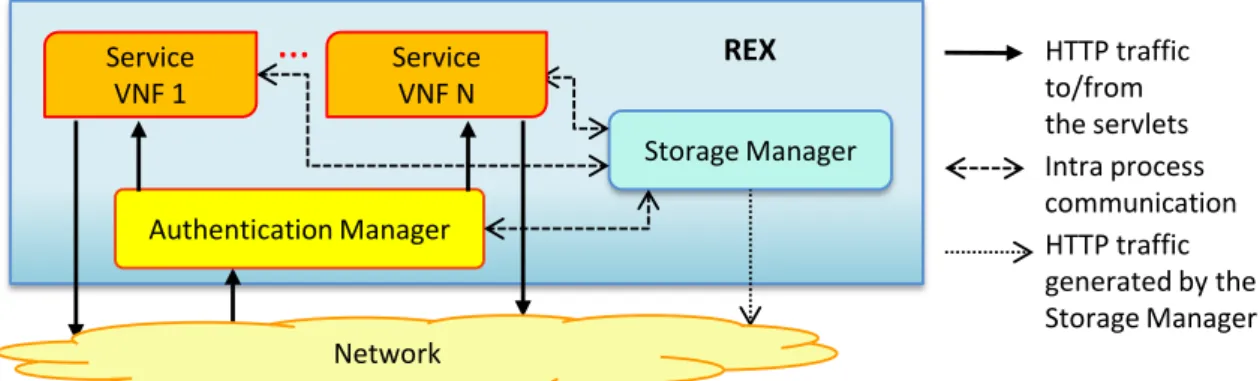
2.3 The Flexible and pROGrammable edge device . . . 33
2.3.1 Storage Service . . . 34
2.3.2 Remote Execution Environment . . . 35
2.3.3 Communication and authentication . . . 36
2.4 Programming the PEX . . . 37
2.4.1 Callbacks . . . 37
2.4.2 PEX Runtime . . . 37
2.4.3 Packet Dispatcher. . . 38
2.4.4 Storage Interface . . . 38
2.4.5 Remote Application Interface . . . 38
2.4.6 Management Interface . . . 39
2.5 Parental control service . . . 39
2.6 Validation . . . 40
2.6.1 Starting the PEX . . . 40
2.6.2 Accessing the RESTO . . . 41
2.6.3 Exploiting the REX. . . 42
2.7 Conclusion . . . 42
3 Toward dynamic and virtualized network services in telecom oper-ator networks 45 3.1 Introduction . . . 45 3.2 Related work . . . 47 3.3 General architecture . . . 48 3.3.1 Service layer . . . 48 3.3.2 Orchestration layer . . . 50 3.3.3 Infrastructure layer . . . 51 3.4 Data models . . . 51 3.4.1 Service graph . . . 52
3.4.2 Forwarding graph and lowering process . . . 55
3.4.3 Infrastructure graph and reconciliation process . . . 57
3.4.4 Network function template . . . 60
3.5 The validation use case: user-defined network services . . . 62
3.6 Prototype implementation . . . 63
3.6.1 The service layer . . . 64
3.6.3 The Universal Node. . . 67
3.6.4 The OpenStack-based node . . . 69
3.6.5 Discussion: Openstack-based Node vs. Universal Node . . . . 72
3.7 Prototype validation . . . 73
3.7.1 Service overview . . . 73
3.7.2 Performance evaluation . . . 74
3.8 Conclusion and future works . . . 77
II
Optimizing packets movement between Virtual
Net-work Functions
79
4 Supporting fine-grained virtual network functions through Intel DPDK 83 4.1 Introduction . . . 83 4.2 DPDK overview . . . 84 4.3 General architecture . . . 85 4.4 Implementations . . . 86 4.4.1 Double buffer . . . 864.4.2 Double buffer + semaphore . . . 87
4.4.3 Single buffer towards the vSwitch + semaphore . . . 87
4.4.4 Double buffer + FDIR . . . 88
4.4.5 Isolated buffers + semaphore . . . 89
4.5 Performance evaluation . . . 89
4.5.1 Double buffer . . . 90
4.5.2 Double buffer + semaphore . . . 92
4.5.3 Double buffer + FDIR . . . 93
4.5.4 Isolated buffers + semaphore . . . 93
4.6 Related work . . . 93
4.7 Conclusion . . . 94
5 Efficient data exchange algorithm for chained virtual network func-tions 97 5.1 Introduction . . . 97
5.2 Related Work . . . 99
5.3 The data exchange architecture . . . 101
5.3.1 Operating context. . . 101
5.3.2 Architecture Overview . . . 101
5.3.3 Execution model . . . 102
5.3.4 Basic algorithm: handling pass-through data . . . 103
5.3.5 Extended algorithm: handling Worker-generated data . . . 109
5.4.1 Properties specification . . . 113
5.4.2 Model details . . . 114
5.4.3 Verification results . . . 115
5.5 Implementation . . . 116
5.6 Experimental results . . . 118
5.6.1 Single chain - Throughput . . . 119
5.6.2 Single chain - Latency . . . 121
5.6.3 Single chain - Comparison with other approaches . . . 121
5.6.4 Single chain - Other tests . . . 123
5.6.5 Multiple chains . . . 124
5.6.6 Network tests . . . 125
5.7 Conclusion . . . 126
6 Transparent optimization of inter-virtual network function commu-nication in Open vSwitch 129 6.1 Introduction . . . 129
6.2 Background . . . 131
6.3 Architecture . . . 132
6.3.1 Detecting p-2-p links . . . 133
6.3.2 Handling the new ivshmemdevice . . . 133
6.3.3 Remapping process . . . 134
6.3.4 Port statistics . . . 136
6.4 Experimental validation . . . 136
6.4.1 Throughput with internal traffic . . . 137
6.4.2 Throughput with physical NICs . . . 138
6.4.3 Latency . . . 138 6.4.4 Establishment time . . . 139 6.5 Related work . . . 140 6.6 Conclusion . . . 140 Conclusions 143 Bibliography 145 Appendix 153
List of Tables
1.1 NFV vs FROG . . . 23
1.2 Protocols and corresponding regex. . . 28
1.3 “One VNF per PEX” vs “Multiple VNFs per PEX”. . . 29
2.1 Latency in accessing the RESTO. . . 42
3.1 Challenges of the considered use case and related solutions. . . 62
3.2 Universal Node vs OpenStack-based Node. . . 72
List of Figures
1.1 The FROG operating context: a network edge node and its end users. 9
1.2 High level view of a FROG node. . . 10
1.3 Possible journey of a packet. . . 12
1.4 Possible journey of a broadcast/multicast packet. . . 14
1.5 Data and control plane. . . 16
1.6 FROG software architecture. . . 17
1.7 Packet exchange between the fvSwitch and PEX. . . 19
1.8 Single vs. multi-server architecture. . . 23
1.9 Throughput with a growing number of PEX. . . 26
1.10 Latency introduced by the node with a growing number of native PEX. 26 1.11 PEX memory consumption. . . 27
1.12 Single vs. multi server. . . 27
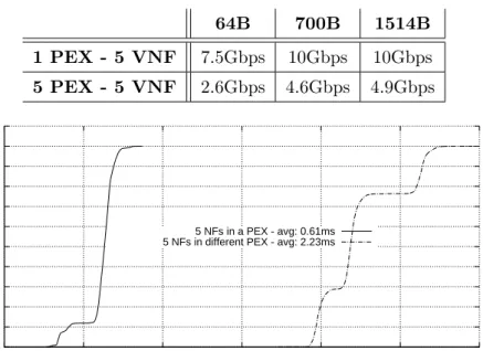
1.13 Latency in case of 5 VNFs running: (i) in the same PEX, (ii) in 5 different PEX. . . 29
2.1 Overview of the entire system. . . 33
2.2 Internal view of the Remote Storage Service. . . 35
2.3 Exploded view of a REX.. . . 36
2.4 Exploded view of a PEX hosting two VNFs. . . 37
2.5 Starting a PEX with four VNFs. . . 41
3.1 Deployment of virtual network functions on the telecom operator net-work. . . 46
3.2 Overall view of the system, including the two implementations of the infrastructure layer. . . 49
3.3 Service graph: basic elements and example.. . . 52
3.4 Cascading SGs. . . 55
3.5 From the SG to the FG: the lowering process. . . 58
3.6 Excerpt of a forwarding graph.. . . 59
3.7 Example of the output of the reconciliation process when mapping a L2 switch functionality in case of two different types of infrastructure nodes. . . 60
3.8 Example of a VNF template.. . . 61
3.10 Logical architecture of the Universal Node. . . 68
3.11 OpenStack-based Node. . . 70
3.12 Use case scenario. . . 74
3.13 Memory consumption. . . 75
3.14 Performance of the infrastructure layer: (a) ping; (b) file transfer. . . 76
4.1 High-level view of a server with a vSwitch and several VNFs. . . 86
4.2 Implementation based on a (different) pair of rings shared between the vSwitch and each VNF. . . 87
4.3 Implementation that exploits theFDIR feature. . . 88
4.4 Throughput with a growing number of VNFs. . . 91
4.5 Latency introduced by the framework. . . 91
5.1 Function chains deployed in a server. . . 98
5.2 Deployment of the algorithm within a server.. . . 102
5.3 Run-time behavior and indexes of the algorithm. . . 109
5.4 Binding primary buffer - auxiliary buffer. . . 112
5.5 Throughput of a single function chain with the algorithm presented in this chapter. . . 120
5.6 Internal throughput of the function chain, with real Workers and a 1M packets in memory. . . 121
5.7 Latency introduced by the function chain with a growing number of cascading Workers. . . 122
5.8 Throughput of a single function chain when other data exchange al-gorithms are used. . . 122
5.9 Results with a growing number of function chains running in parallel, each one spotting two Workers in cascade. . . 125
5.10 Results with a function chain of growing length, with the Master accessing to the network. . . 126
6.1 Traffic crossing several VNFs: (a) the “abstract” service graph; (b) its implementation on a server. . . 130
6.2 Sharing DPDK data structures between OvS and VMs. . . 132
6.3 Different implementations for thedpdkr port. . . 132
6.4 ivshmemdevice for port remapping. . . 134
6.5 Test setup.. . . 137
6.6 Memory-only traffic. . . 137
6.7 Traffic using physical NICs. . . 137
6.8 # of cores required/assigned during the tests. . . 138
6.9 Latency when physical NICs are involved. . . 139
Part I
Delivering user-oriented network
services in an NFV scenario
Overview
The way network services are delivered is going to dramatically change in the next few years thanks to the Network Function Virtualization (NFV) [43] paradigm, which allows the network services to experiment the same degree of flexibility and agility already available in the cloud computing world. In fact, NFV proposes to transform network functions that today run on dedicated appliances (e.g., firewall, WAN accelerator) into a set of software images that can be consolidated into high-volume standard servers, hence replacing dedicated middleboxes with virtual ma-chines implementing those Virtual Network Functions (VNFs).
NFV is mainly seen as a technology targeting network operators, which can exploit the power of the IT virtualization (e.g., cloud and datacenters) to deliver network services with unprecedented agility and efficiency and at the same time achieve a reduction of OPEX and CAPEX. However, also theend users (e.g., xDSL
customers) can benefit from NFV, as this would enable them to customize the set of services that are active on their Internet connection; in other words, NFV would enable end user to personalize their Internet experience.
The possibility to enable multiple players, including the end users, to deploy network services by means of the NFV paradigm is explored in this part of the dissertation.
Chapter 1 presents FROG, a software architecture allowing both the end users
and other players such as service providers to install and operate their own VNFs on a network edge node. Particularly, end users connected to the node can create their customized network services that are then applied to their own traffic independently from the physical terminal in use (e.g., smarthphone, tablet, ect.). Numbers from ISPs indicate that, on the same Broadband Remote Access Server (BRAS) (which may be a deployment scenario for FROG), the termination of 20K ADSL lines is not uncommon. Then, the proposed architecture needs to guarantee an adequate level of performance even when a huge number of end users run together their own VNFs on the node. The prototype demonstrates that this objective is feasible and the resulting architecture is scalable; in addition, such an architecture guarantees traffic isolation among VNFs deployed by different players.
Chapter 2 validates the FROG platform from the point of view of the service developer; in particular, the chapter presents the API exported to the developers, as well as a complex parental control service built on top of such an API.
Chapter 3 extends the FROG concept by proposing a multilayer architecture that, leveraging different levels of abstraction, can orchestrate and deploy generic network services on the whole network of a telecom operator, ranging from the home gateway installed in the customer premises to the data center servers. This architec-ture is then exploited to deliver generic services in presence of multiple concurrent players (e.g., network operators, end users), leveraging a new simple data model.
Particularly, the chapter proposes a description-based approach allowing the deploy-ment of agile, impledeploy-mentation-independent and high-level network services over a distributed set of resources. The resulting data model can abstract generic services, including both middlebox-based (e.g., firewalls, NATs, etc.) and traditional LAN-based ones (e.g., a BitTorrent client). Finally, two distinct prototypes, originated by different design principles, are implemented in order to validate the proposal with the aim of demonstrating the adaptability of the approach in different contexts.
Chapter 1
A scalable and massively
multi-tenant platform for
user-oriented network services
1.1
Introduction
Thanks to the arising of Network Function Virtualization (NFV) [43] it is possible, perhaps for the first time, to influence network operations through software appli-cations developed by third parties; however, at the best of our knowledge, currently a few players, namely network manufacturers and network operators seem to be allowed to create, install and operate Virtual Network Functions (VNFs) on the network nodes.
Going against this trend, this chapter1 presents FROG, aFlexible and
pRO-Grammable edge device that offers to different players, including end users, the
possibility to customize the behavior of the device itself through the deployment of their own virtual network functions. In fact the end users, with their imagination, are the ones that drove the innovation in the PC and smartphone markets with the creation of many unexpected applications, and we expect them to be the ones that will contribute most to network evolution. In this respect, we envision for Network Service Providers (NSPs) the possibility to evolve ininfrastructure providers (a sort
of new Network IaaS), offering to multiple players a pipe that transports bit (the
network) and a programmable platform where those bits can be processed and even modified in transit.
FROG classifies the players enabled to deploy VNFs into two categories: (i) end users, i.e., the ADSL customers who connect to the Internet through a FROG
1The work of this chapter is partially published in [79] and partially described in the master
1 – A scalable and massively multi-tenant platform for user-oriented network services
node and that can deploy VNFs only on this particular FROG instance; (ii) other
entities such as Internet Service Providers (ISPs) and content providers, which are not directly connected to FROG, but that are anyway enabled to deploy VNFs on the node itself. This partitioning represents one of the key points of our framework, and it is exploited to decide the order in which a packet belonging to multiple players is processed by the VNFs they have deployed on the FROG node.
It is worth noting that players such as ISPs may be interested to exploit FROG to run, as software images, those applications traditionally executed in dedicated appliances or proprietary boxes, such as NAT and WAN accelerators. Instead the end users may be more interested in moving on FROG (and then into the network) those applications today executed in their many devices (e.g., personal firewall, parental control), in order to obtain exactly the same service regardless of the device they are currently using.
The fact that several players are enabled to deploy their own VNFs on FROG may result in a very huge number (even thousands) of VNFs executed simultaneously on the node. The support of this massive number of VNFs is not trivial, and it requires to address several issues.
First of all, VNFs cannot be executed in full fledged virtual machines, because
they would be too expensive in terms of hardware requirements, namely memory and processing power. Then FROG defines a lightweight container, called Private EXecution environment (PEX)(see Figure1.2), which is in charge of executing all the VNFs belonging to the same player; in the remainder of this chapter we will
demonstrate that a single FROG node implemented on general purpose hardware can execute thousands of VNFs at the same time (eight thousands in our setup). Moreover, to support even more VNFs2, we designed a distributed version of the
framework, in which a single FROG deployment actually consists of a cluster of
servers. It is worth noting that the multi-tenancy of FROG imposes that the frame-work guarantees isolation among VNFs, so that a malicious application installed by userA cannot interfere with applications belonging to user B. Then, to
guaran-tee isolation among players, FROG (i) executes each PEX into a different Docker
container [3], and (ii) exploits a packet dispatching mechanism not based on
zero-copy techniques, which would improve performance but that would not ensure the required level of isolation.
Obviously, a huge number of VNFs cannot come at the expense of performance; in fact, our prototype demonstrates that this platform can support thousands of users, each one running its own VNFs at reasonable speed, and that its overall performance, when FROG is installed on commodity hardware, is excellent (several Gbps on a
2In fact, numbers from ISPs indicate that in a deployment scenario such as a Broadband Remote
Access Server (BRAS), the termination of 20K ADSL lines (and not users!) on the same network box is not uncommon.
1.2 – Related Work
single machine). The achievement of this goal required a careful implementation of the component that classifies packets and provides them to the proper VNFs (the
FROG vSwitchin Figure1.2), while the multi-server version further increases the
performance in demanding environments.
This chapter is structured as follows. Section 1.2 analyses the related work, while Section 1.3 provides an overall view of the FROG platform, which is then detailed in Section1.4. The implementation of the framework is instead described in Section1.5. Section1.6 compares FROG with the NFV model; experimental results are then shown in Section 1.7, while Section 1.8 finally concludes the chapter.
1.2
Related Work
Several works in literature address the possibility of consolidating many network functions on the same physical hardware. However, FROG defines a service model in which the end users connected to the node play a central role (Section 1.4); at the best of our knowledge, no other platform gives such an importance to the end users, although some of them (ClickOS [64] and NetVM [55]) do not prevent end users to deploy VNFs.
Particularly, ClickOS [64] bases on XEN [23] to create a multi-tenant software
middlebox consisting of many ClickOS instances, i.e., virtual machines (VMs) with Click [71] running on top of a minimal operating system. Unlike ClickOS, FROG defines a service model in which the VNFs deployed by end users who are the source and the destination of network traffic are respectively the first and the last VNFs to operate on such a traffic; hence, FROG has been explicitly designed and optimized for this type of service. Moreover, results provided in [64] do not show how ClickOS scales with the number of VNFs, while the support of thousands of active players (and then VNFs) at the same time is one of the goals of the FROG platform.
Similar differences exist also between FROG andNetVM [55], a platform built
on top of KVM and the DPDK [56] framework, designed to efficiently provide traffic to VNFs deployed as different VMs. Notably, NetVM guarantees traffic isolation among “untrusted” VMs, while packets are moved in a zero-copy fashion among “trusted” VMs.
CoMb [86] is a software middlebox that optimizes the resource usage of VNFs
running on the same server. Particularly, a centralized controller selects the CoMb node in which deploy a VNF, using information such as the resources required by this VNF, the resources available on the nodes, and the traffic on which the VNF must operate. However, aspects such as the multi-tenancy, the traffic isolation among VNFs of different tenants, and the execution of thousands of VNFs on the same server are not mentioned in [86].
SHG [95] proposes an home gateway that can host both data plane functions
1 – A scalable and massively multi-tenant platform for user-oriented network services
but that does not consider the end user as players that can reprogram the box. The home gateway is also the target of [96], which proposes to partition the node in multiple slices, each one assigned to a different provider. Each slice is completely orthogonal to the others and has its own reserved resources (i.e., bandwidth, entries in the forwarding table, CPU) and control logic. However, in this case there is no provision to customize the packet processing.
Another work that we can cite isClick[71], which is one of the first proposals of a
framework to customize the packet processing in the network. Compared to FROG, it presents several limitations. For instance, its processing path is rather static and cannot be changed at runtime; furthermore, it does not allows to dynamically load/unload network services and the multitenancy.
xOMB [22] is a software architecture for building programmable middleboxes;
however, while FROG supports VNFs operating at any layer of the network stack, xOMB is particularly oriented to application-layer functions (e.g., HTTP load bal-ancer). APLOMB [87] proposes to outsource enterprise middlebox functions to
the cloud, which may be appropriate only in some cases as it could pose non trivial problems of traffic tromboning and latency.
ServerSwitch [61] is a programmable platform for datacenters that integrates
an ASIC switching chip in a commodity server. It allows the implementation of new forwarding algorithms executed in the switching chip, which can be programmed by control plane applications running on the CPU. However, ServerSwitch seems to support only some particular VNFs (e.g., bridging). PacketShader [49], instead,
is mainly a software router, although some other applications (e.g., IPSec gateway) are possible, but only one at a time. Notably, it exploits Graphical Processing Units (GPU) to accelerate some processing tasks.
As a final remark, it is worth pointing out that the work described in this chapter has been done in 2013, when the literature on NFV was still quite poor. More recent works on this research area are then discussed in Chapter3, which describes a more recent architecture to deploy generic network services in the whole network of the telecom operator.
1.3
Overview
As shown in Figure 1.1, FROG operates in the context of a network edge node directly connected to the final users. Its main idea is to offer to a massive number of users the possibility to execute VNFs operating on (a portions of) the network traffic flowing through the edge device, according to a service model that in principle resembles to NFV. The FROG service model is based on two ingredients: (i) the
capability to associate a portion of traffic, identified by a set of rules operating mostly on protocol field values, to a sort of network partition callednetwork tile, and (ii) an execution environment that hosts the VNFs that have to process the traffic
1.3 – Overview
corresponding to a specific tile, called Private EXecution environment (PEX).
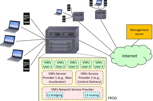
VNFs Service Provider 1 (e.g., Wan
Accelerator) VNFs User 1 VNFs User 3 VNFs User 5 VNFs Service Provider 2 (e.g., Content Delivery) VNFs User 4 VNFs User 2
VNFs Network Service Provider L2 bridging L3 routing
FROG
Management server
Internet
Figure 1.1: The FROG operating context: a network edge node and its end users. According to Figure 1.2, each PEX is associated with a specific player (i.e., an end user or other entities such as a content provider or a network operator), who has full control over the applications running in it, being able to choose which VNFs have to be executed and the order in which they are called. In addition, FROG defines a set of permissions granted to the VNFs running in each PEX, such as the
possibility to modify and/or drop packets.
The capability to define tiles and permissions allows FROG to support multi-tenancy. Depending on the rules used to define network tiles, we may have either the possibility to partition the traffic into orthogonal or overlapped tiles. A packet that matches multiple tiles has to be delivered to several PEX, and hence we need to define a proper precedence level to determine in which order each PEX should receive the traffic.
Traffic coming from a new end user is redirected to a captive portal, which implements the user authentication. If the authentication is successful, a new PEX is created that receives all the packets belonging to the user’s tile, defined by the traffic generated by/directed to the new end user’s device. This PEX hosts a set of staked VNFs, installed by the user himself, which will be called sequentially on each user’s packet. Finally, other PEX are created ahead of time by customers such as ISPs and content providers, and that can operate on traffic belonging to multiple end users.
1 – A scalable and massively multi-tenant platform for user-oriented network services
PEX 1 (for network tile 1)
Virtual switch
Parental control Personal firewall
PEX 2 (for network tile 2)
QoS VPN client
PEX 3 (for network tile 3)
Web cache
PEX 4 (for network tile 4)
Network monitor
User 1 Tile and PEX
owner
User 2 Content provider Network operator
Network tile 3
Select web traffic
Network tile 1
Select traffic of user 1
Network tile 2
Select traffic of user 2
Network tile 4
Select all traffic
Network traffic
Figure 1.2: High level view of a FROG node.
1.4
FROG design
This section presents the key aspects of FROG, which include the network tiles, the PEX and the permissions that can be associated with it, and the order in which a packet matching several tiles is provided to all the proper PEX. Moreover, it also presents the FROG data and control planes, and the management server.
1.4.1
Network tiles
Traffic entering in FROG must be classified to determine the tile(s) it belongs to, then packets need to be sent to the proper set of PEX for the processing. For the classification, FROG supports a set of rules operating mainly on protocol fields, and that are similar to the ones used in OpenFlow [68]. As tiles can be defined by multiple rules as shown in Figure1.3, a packet belongs to a tile if it matches at least one of the rules defining the tile itself.
The capability to create partitions over the network and to allow different players to operate on their traffic does not represent a novelty [88]. However, those partitions were always oriented to guarantee network isolation, and then they do not overlap. As our objective is not to provide network isolation, FROG defines two types of partitions, or tiles in the FROG terminology, namely the vertical tiles and the horizontal tiles.
Avertical tile includes all theunicast traffic of a specific end user connected to
1.4 – FROG design
the user terminal3, namely{M AC
user → ∗, ∗ →M ACuser}; these rules respectively
representall the packets sent by that end user, andall the unicast traffic destined to the end user himself. It is worth pointing out that, taking into account the direction
of a packet (i.e.,from the end user, ortowardsthe end user), vertical tiles are not
overlapping, since a (unicast) packet will match at most one vertical tile in each direction (the tile of the sender and the tile of the receiver)4. The Default vertical
tile is a particular tile that is in charge of all the unicast traffic coming from an
access port (i.e., from a port connected to the end users) and that does not match any other vertical tile. In practice, it handles the traffic belonging to a new end user connected to FROG, who still does not have his vertical tile configured (and his PEX running).
Unlike vertical tiles, horizontal tilesare defined with an arbitrary set of rules,
not necessarily symmetric with respect to the network traffic, operating on any supported field. In this case we may have network tiles with overlapping rules, which means that a packet can belong to several horizontal tiles at the same time.
Figure 1.3 shows a possible configuration of FROG with rules defining both vertical and horizontal tiles. As evident, a PEX under the control of an end user is allowed to operate only on the traffic belonging to that user, i.e., on the packets to/from the user himself. Vice versa, horizontal tiles are appropriate to implement traditional network middlebox functions working on traffic aggregates (e.g., a web cache); hence, they appear more appropriate for hosting VNFs of players such as service providers or network operators.
1.4.2
Service order
A packet that enters in FROG through an access port is immediately checked against the rules defining the vertical tiles, in order to identify the tile associated with the end user who is sending the traffic. Given the structure of the rules defining vertical tiles, at most one of them is matched, and the packet is then provided to the PEX associated with that tile, so that it can be processed by the VNFs running in that PEX. A packet sent by an unauthenticated user matches the Default vertical tile, and hence it is processed in the Default vertical PEX. This way, the user can be
authenticated, and the vertical tile identifying his traffic, as well as the PEX running his VNFs, are created.
After that the packet has been processed in the PEX associated with the sender user, we move to horizontal tiles. The matching against horizontal tiles is more
3Note that this parameter may be different in other implementations (e.g., ATM VPI/VCI),
provided that it allows to select univocally the traffic of a single user.
4Packets coming from (directed to) the Internet matcha single vertical tile, since their source
1 – A scalable and massively multi-tenant platform for user-oriented network services
Network tuples PEX Permissions
MAC1 * * MAC1 User 1 read/ write MAC2 * * MAC2 User 2 read/ write * - {MAC1, MAC2) *
* * - {MAC1, MAC2) Default
read/ write
Network tuples Priority PEX Permissions
* tcp port 80 tcp port 80 * 40 SP1 read * net 8.8.8.0/24 net 8.8.8.0/24 * 30 SP2 read/write * * 20 NET OP read/write/ forward Vertical tiles Horizontal tiles
PEX Network Operator (network monitor)
PEX Service Provider 1 (web cache)
PEX Service Provider 2 (WAN accelerator)
PEX
Default User 2 PEX
to/from to/from PEX
User 1
Figure 1.3: Possible journey of a packet.
complicated because their rules can overlap, hence a packet can match multiple horizontal tiles. For this reason, they are associated with a priority, whose value is
unique within FROG. Hence, the packet will be checked against the horizontal tile with the highest priority and delivered to the corresponding PEX in case of positive matching, then the same operation is repeated with the tile with the second highest priority, and so on.
Finally, before exiting, a unicast packet is checked again against the rules defining the vertical tiles, and then delivered to the PEX running the VNFs deployed by the destination end user.
Given the above rules for the service order, a PEX associated with a vertical tile looks like a portion of the network stack of the user terminal that is moved in the network. In fact, it is the first PEX that receives the traffic sent by the device as soon as it enters in FROG, as well as it is the last PEX that processes the packets before they leave FROG towards the user terminal. Hence, for example, a personal firewall running in the user terminal is functionally equivalent to the same application running in the PEX associated with that user5.
5For the sake of precision, some differences still exist. The most important refers to the visibility
over encrypted traffic, which can be obtained more easily by an application running in the user terminal. This problem has not been addressed in work presented in this chapter, and it is left for future work.
1.4 – FROG design
In the example shown in Figure1.3, a packet enters in FROG and is first delivered to the vertical tile that matches its source MAC address, then it hits a variable number of horizontal tiles traversed in an order defined by their priority, and finally it concludes its journey by hitting the vertical tile that matches its destination MAC address. Note that this processing path is valid independently from the VNFs running in each PEX.
The fact that VNFs can (almost) arbitrarily change the packet content may lead to a situation in which a packet that, in the next processing step, should have been delivered to tileT1, is modified so that the next matching tile becomesT2. This may create a cyclic workflow, in which PEX A modifies the packet so that it matches the tile of PEX B, which modifies the packet to match the tile of PEX A, endlessly. To avoid this problem, a packet exiting from the vertical tile of the sender user will be matched against horizontal tiles, no matter which modifications have been done to the packet content. Similarly, if a packet matched an horizontal tile with priority Φ, it will be checked against all the tiles having priority < Φ. Finally, after that
a packet has been processed in the PEX of the destination end user, it is sent out of FROG. This way, the PEX calling order is always a direct acyclic graph, hence guaranteeing that a packet cannot enter into a processing loop involving different PEX.
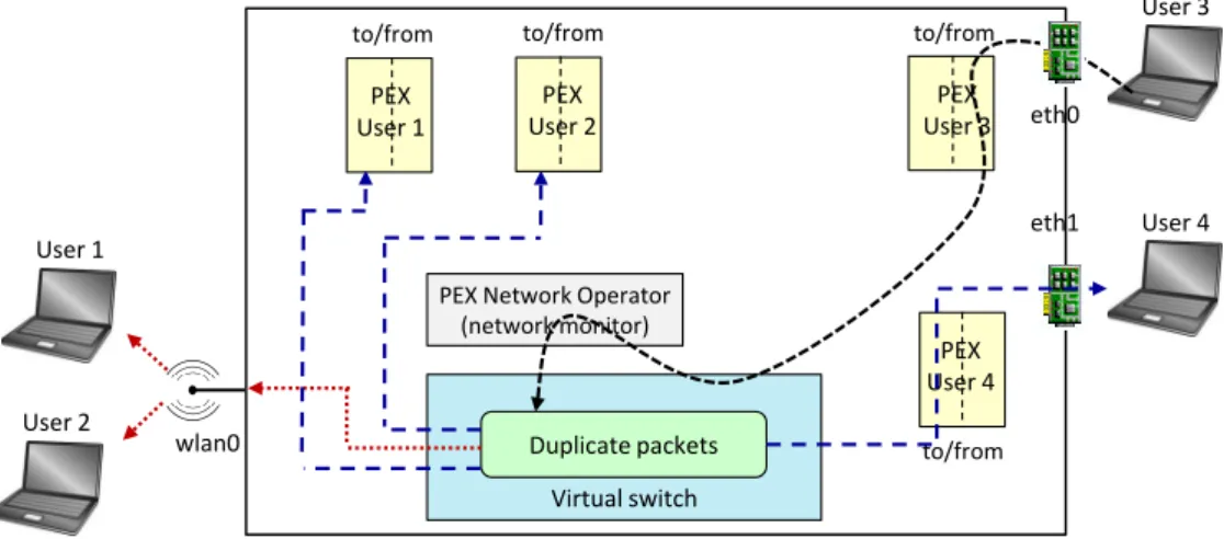
Broadcast and multicast traffic
A broadcast/multicast packet entering in FROG is first delivered to the vertical PEX of the end user who is sending that packet; then, it is checked against horizontal tiles in an order defined by their priority, as happens in case of unicast traffic. Finally, when the packet has to be delivered to the vertical PEX associated with the end user who is the destination of the packet itself, the time has finally come to duplicate this traffic.
In principle, FROG should duplicate the packet as many times as the number of access ports on which the packet has to be sent, and then each copy should be delivered to the vertical PEX of the end user who is connected to that port. Finally, if not dropped by any VNF, the packet is delivered to the user terminal. This is the case of User4in Figure 1.4, where VNFs running in User4’s PEX receive the packet
and (if permissions allow) can even drop it; in this case, the above mentioned packet will never reach User4.
Vice versa, if many user devices are connected through the same access port (such as User1 and User2 that share the same WiFi interface in Figure 1.4), the
behavior is different. In this case, the packet is further duplicatedN+1 times, where N is the number of terminals sharing that interface. A first copy of the packet is
delivered directly to the interface, hence reaching immediately the user devices. The other N copies will be sent, marked with a special flag, to the corresponding PEX
1 – A scalable and massively multi-tenant platform for user-oriented network services
a network monitor can update its internal counters). However, this packet will be dropped by FROG as soon as it exits from the PEX, hence losing any modification that may have been occurred to the packet. The rational for this behavior is to offer to the VNFs running in the PEX the possibility to receive exactly the same traffic as they would be executed in the user terminal; however, in case of shared interfaces we cannot give them the possibility to modify the packet, as a single copy of each packet must be sent across the shared port and we are unable to handle possible conflicts when the different PEX touch the packet (modify/drop) in an incoherent way.
PEX Network Operator (network monitor) Virtual switch User 3 eth0 Duplicate packets User 1 User 2 User 4 eth1 wlan0 PEX User 1 PEX User 2 PEX User 3 PEX User 4
to/from to/from to/from
to/from
Figure 1.4: Possible journey of a broadcast/multicast packet.
1.4.3
Private EXecution environment
As previously mentioned, the PEX is the execution environment running all the VNFs installed by a single player. In particular, it receives (all) the traffic matching the network tile to which it belongs to, and in turns it provides these packets to the VNFs it is running. A packet entering in a PEX will traverse all the applications executed in that PEX in an order decided by the PEX owner and that, in the current prototype, has to be strictly sequential. In case a VNF creates a new packet, this will traverse all the applications that follow, while the ones that appear earlier in the sequence will have no visibility on that packet.
Some network privileges can be associated with the PEX. For instance, end users are usually enabled to do whatever they want on their traffic, including generating and/or modifying packets traversing their PEX. A PEX of an entity in charge of network monitoring may have instead a “read mode” privilege. Further, other PEX could have also access to network parameters, and influence the forwarding process of the FROG node, such as determining the output interface of a given packet. Then
1.4 – FROG design
the PEX is also in charge of enforcing these permissions, and then of preventing that VNFs perform illegal operations.
The possibility granted to VNFs running in a PEX with thepacket modification
permission, to potentially change arbitrarily the packet content, including the pos-sibility to create new packets, may lead to packets that do no longer belong to the tile associated with the current PEX, which we feel may not be acceptable. For this reason, the PEX allows modifications to the packet content as long as the modi-fied/new packet still belongs to the tile associated with that PEX. For instance, a
packet that is under processing in the SP1 PEX in Figure 1.3 cannot be modified
to become tcp port 1000 → tcp port 8080, as in this case it would no longer
belong to that tile. However, the enforcement of these constraints introduces some additional overhead in the FROG processing, as packets exiting from a PEX are checked for tile conformance and, if the control fails, a shadow copy is sent to the next processing component instead of the original packet6.
As a final remark, memory spaces among different PEX are disjoint, so that VNFs installed by a user cannot intercept/corrupt the traffic belonging to another PEX. Instead, this property is not guaranteed to the VNFs running in the same PEX, which share the same address space for performance reasons. Therefore we can expect that a misbehaving VNF could affect the execution of the other applications running in the same PEX, although this may be considered reasonable since they all belong to the same player.
1.4.4
Data plane, control plane and management server
As depicted in Figure 1.5, FROG includes both a data plane and a control plane portion.
The data plane consists of the PEX and the VNFs deployed in these PEX, which operate on a portion of the traffic flowing through the node, i.e., on a network tile.
The control plane portion, instead, is connected to the rest of FROG through a virtual port, named tap0 in the picture. The tap0 interface is visible from the
TCP/IP stack of the operating system (while all the other ports of FROG are hidden), hence all the traditional TCP/IP applications can be executed on that interface (e.g., the captive portal to authenticate new users, a DHCP server, etc.).
Finally, the entire set of FROG nodes is coordinated by an external management server, as shown in Figure 1.1. It contains the user database, the permissions, the list of VNFs, and more. Furthermore, it stores the VNFs associated with each user, which are in fact copied from this server to the proper FROG node each time a new
6In fact, this algorithm has been optimized and a complete shadow copy of the packet is created
only when PEX has read-only privileges over the packet content. In case of read-write privileges, only the fields that concur to determine the network tile are copied.
1 – A scalable and massively multi-tenant platform for user-oriented network services
PEX Service Provider 1 (web cache)
PEX Network Operator (network monitor) PEX Service Provider 2
(WAN accelerator) User 3 Virtual switch User 1 User 2 PEX User 1 PEX User 2 PEX User N DHCP Server TCP/IP stack Captive portal ... Control plane Data plane
eth0 eth1 eth2 tap0
…
Figure 1.5: Data and control plane. PEX has to be activated, e.g., each time an end user logs in.
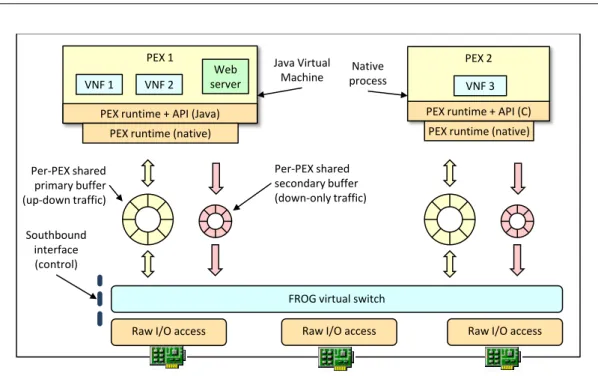
1.5
Implementation
This section presents the FROG software architecture that includes, in addition to the several PEX associated with the users, the FROG virtual switch (which is the component in charge of exchanging packets with the network and implementing the network tiles) and the exchange buffers. The entire architecture, which has been designed to efficiently scale with the number of VNFs, is depicted in Figure1.6.
1.5.1
Virtual switch
TheFROG virtual switch (fvSwitch)is the component in charge of
implement-ing the network tiles, then of providimplement-ing the packets to the proper PEX accordimplement-ing to the service order defined in Section 1.4.2. Hence, this module cyclically repeats the following main operations: (i) read packets from the physical network ports,
clas-sify the traffic (according to the network tiles) and deliver it to the PEX associated with the first matched tile; (ii) read packets from each running PEX, classify and
forward them to the proper next PEX, or send the packets on the network through the proper physical network port(s).
The fvSwitch relies extensively on batch processing; in fact, phase (i) is repeated
multiple times by reading several packets from each port before moving to phase (ii),
where several packets per PEX are processed in a row before going to the next PEX. This allows the fvSwitch to execute code that has an high degree of locality and to concentrate memory accesses to nearby locations (e.g., reading several packets in a
1.5 – Implementation
PEX 1
FROG virtual switch VNF 1 VNF 2
PEX runtime + API (Java) PEX runtime (native)
PEX 2 PEX runtime + API (C)
VNF 3 PEX runtime (native) Java Virtual
Machine processNative
Southbound interface (control) Per-PEX shared secondary buffer (down-only traffic) Per-PEX shared primary buffer (up-down traffic)
Raw I/O access Raw I/O access Raw I/O access
Web server
Figure 1.6: FROG software architecture.
row), which have an important impact on the performance of the system because of the capability to exploit cache (code and data) locality.
Since the fvSwitch is supposed to be traversed by a huge amount of traffic (all the packets flowing through the node, each one multiple times), this module operates in polling mode. In fact, if interrupts are used to notify the packets arrival, the throughput can drop dramatically with high packet rates [70]. Moreover, to avoid expensive context switches [60] and limit the L1/L2 cache pollution, a CPU core is statically allocated to the fvSwitch. Note that this module has been designed to use a single core, as we would like to allocate all the others to the PEX.
The fvSwitch has raw access to network ports through accelerated NIC drivers, which enable “direct” I/O with the hardware without involving the operating system. Currently we support DNA [44], although a fallback mode exploiting libpcap has
been implemented in order to allow FROG to operate on NICs that do not support accelerated drivers.
Finally, the fvSwitch is also responsible to duplicate broadcast and multicast packets according to the rules described in Section 1.4.2.
Why yet another virtual switch
In principle, existing virtual switches such as Open vSwitch (OvS) [76], whose for-warding table can be configured by means of SDN protocols [80] (e.g., Openflow), can be used in FROG to move packets among PEX and the physical network inter-faces. However, we decided to implement the fvSwitch from scratch, for a number
1 – A scalable and massively multi-tenant platform for user-oriented network services
of reasons.
First, as described in Section 1.4.2, in FROG we have a well defined service model (the packet is first matched against rules defining vertical tiles, then it is sent to the PEX associated with the matched horizontal tiles, and finally it is again matched against rules defining the vertical tiles), then the fvSwitch forwarding table and matching logic have been designed and optimized to implement such a service model. Second, as detailed in the next section, the fvSwitch exchanges packets with a PEX using a couple of memory buffers shared with the PEX itself, and optimized for the NFV case in which almost all the packets provided by the virtual switch to a VNF will eventually come back to the vSwitch itself.
OvS, as any other Openflow-based virtual switch, is instead designed to be generic, and then it does not do any assumption on the order in which rules have to be matched, as well as it is not optimized for the case in which packets sent through a port (e.g., toward a VNF) will likely come back through the same port.
1.5.2
Packet buffers
While designing the internal packet exchange mechanisms between the fvSwitch and the PEX, we had to consider two opposite requirements: performance, which
suggests to use a single buffer shared among all the components in order to exploit a zero-copy algorithm, and isolation, which requires each PEX to have its own
dedicated buffer in order to guarantee that a VNF can only have access to packets that belong to its tile. The resulting mechanism is a mixture of those requirements: each PEX has its own buffer shared with the fvSwitch, hence a packet traversing
N PEX has to be copied by the fvSwitch N times. However, each packet is copied
only once in each buffer, for both the up and down trips. In fact, even if this communication channel can be modeled with two FIFO queues, one bringing packets from the fvSwitch to the PEX and the other for the opposite direction, we exploit an algorithm (extensively detailed in Chapter5) that moves a packet from the fvSwitch to the PEX, and then back to the fvSwitch without any copy of the packet within the PEX itself.
As shown in Figure1.6, each PEX shares two circular buffers with the fvSwitch: theprimary buffer is used by the fvSwitch to send packets to the PEX and to receive
them back once their processing has been completed, while the secondary buffer is
used only for the traffic that is generated by VNFs, as the primary buffer does not accept insertions of new packets from the PEX.
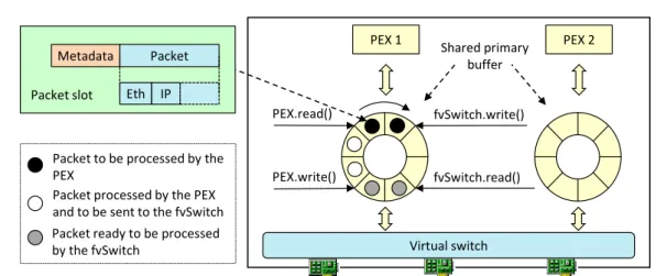
The algorithm that manages the primary buffer, shown in Figure 1.7, uses four indexes, which are respectively a pointer to the last packet written by the fvSwitch in the buffer (fvSwitch.write()), a pointer to the last data that has actually been
read (and processed) by the PEX (PEX.read()), the oldest packet that has been
1.5 – Implementation fvSwitch.write() PEX.read() PEX.write() fvSwitch.read() Packet Metadata Eth IP Packet slot
Packet to be processed by the PEX
Packet processed by the PEX and to be sent to the fvSwitch Packet ready to be processed by the fvSwitch
PEX 1 Shared primary PEX 2 buffer
Virtual switch
Figure 1.7: Packet exchange between the fvSwitch and PEX.
delivered to the next PEX in the chain, and finally the next packet that will be drained by the fvSwitch (fvSwitch.read()) and sent to the next PEX. Note that
this buffer is lock-free, hence very efficient; moreover, in the implementation we took care not to access too often to the shared indexes (we use shadow copies instead) in order to minimize the cache synchronization cost among processes running in different CPU cores.
In addition, the primary buffer is operated through a batching mechanism; in fact, the fvSwitch writes several packets before signaling the PEX over a shared semaphore, waking it up7. This allows the PEX to be scheduled (hence starting
its processing) only when a reasonable amount of packets is present in the buffer, hence limiting the number of context switches in the system and exploiting at best memory locality as in the fvSwitch. Obviously, a timeout has been implemented as well in order to avoid packets starving in the buffer in case the PEX receives limited amount of traffic over time. The PEX will suspend itself only when no packets waiting to be processed are present in the buffer. To facilitate batch processing in the fvSwitch, thePEX.write()pointer is updated only when the amount of packets
processed in the PEX exceeds a threshold, or when there are no more packets to be processed.
The primary buffer is well suited for packets that enter in the PEX, traverse all the local VNFs, and return back to the fvSwitch. However, it may happen that: (i)
a packet is dropped by a VNF, and then it cannot continue its journey; (ii) a VNF
modifies a packet so that it exceeds the MTU, hence requiring to be split in multiple fragments; (iii) a VNF generates new packets.
The first point is addressed by setting a special flag in the packet metadata (Section1.5.4) that informs the fvSwitch to drop that packet as soon as it is received
7The fvSwitch is aware of the status of the PEX, i.e., running or waiting for packets, thanks to
1 – A scalable and massively multi-tenant platform for user-oriented network services
back in the buffer. Instead, points (ii) and (iii) require the secondary buffer, which
is used by the PEX to send its own generated packets to the fvSwitch. This buffer is a traditional (circular) FIFO queue: a special flag in the packet metadata of the primary buffer informs the fvSwitch that, after that packet, the followingN packets
have to be read from the secondary buffer, before returning to drain the traffic from the primary buffer.
Currently, both buffers have slots with a fixed length, whose size is equal to the maximum packet size of the network8. Moreover, they are allocated in memory
using huge pages, in order to reduce the pressure over the Translation Lookaside Buffer (TLB).
1.5.3
Private execution environment
Each PEX is implemented as a different process running all the VNFs belonging to
a specific player. In particular, we defined (and implemented) two flavors of PEX: one privileges the features offered to the users, while the other is more oriented to the achievement of high performance.
The former type of PEX is a Java Virtual Machine (JVM) running Java VNFs and that, as shown in Figure 1.6, is enriched with different components. First, a native library written in C and based on the Java Native Interface (JNI) takes care of the interface with the rest of the system (e.g., accessing to the shared buffers). Second, a set of Java classes that handle the communication among the VNFs de-ployed in the PEX, implement the dynamic loading/unloading of the VNFs9, and
export a rich set of API to VNFs developers (described in Chapter 2). Third, a web server that is used for management (e.g., to handle the command to load/un-load applications) and exported to VNFs for their own purposes (e.g., configuration, visualization of internal data, etc.).
The second type of PEX is instead a pure native process that supports VNFs written in C/C++, which have to be linked with another native library, written in C, that implements the interface with the rest of the system. The number of features are reduced in this case (no dynamic load/unload of VNFs, simpler API exposed to VNFs developers, no web server) but it guarantees higher performance with reduced requirements in terms of both CPU and memory. In fact, the JNI layer used in the Java PEX is known to be rather inefficient, hence increasing considerably the processing cost per packet; furthemore, the memory footprint of the JVM with the required pieces (JNI, web server, etc.) reaches about 18MB, which may represent a
8In this respect we disabled the TCP Large Receive Offload on the NIC, as this function merges
multiple TCP segments creating packets up to several tens of kilobytes.
9In a first phase we used OSGi for this purpose, but we found its memory requirements
1.5 – Implementation
limitation when a massive number of PEX have to be executed concurrently on the same machine.
As mentioned in Section1.5.2, PEX operate according to a blocking I/O model, hence freeing CPU resources when no packets have to be processed. This allows to execute a number of PEX that is far beyond the number of CPU cores available on the machine, as we expect that, in average, each PEX stays idle most of the time (it just processes the traffic of a single player). In fact, the implemented techniques for efficiently exploiting CPU cycles (memory locality, a few context switches) allow to potentially execute thousands of PEX on a single physical server.
To prevent that VNFs consume too many resources (and hence to increase the number of users supported), a PEX is executed on a single CPU core; however, this may limit the throughput of the system in case few of them are installed, as we are unable to exploit all the available cores. An extension that allows a PEX to exploit multiple cores is left to our future work.
Finally, it is worth nothing that the permissions, which are one of the peculiarities of FROG , introduce a noticeable overhead in the PEX processing. In fact, they must be enforced in each PEX in order to guarantee that VNFs do not perform forbidden operations, such as the shadow copies mentioned in Section 1.4.1. Although we took care of implementing the permission checking very efficiently, we found that this part of the code could slow down the system throughput up to 10%.
Resource isolation
As the FROG owner does not have any control on the VNFs installed in the PEX, the framework should limit the effects of malicious applications. Unfortunately, the solution to run each PEX into a different virtual machine is not compatible with our scenario in which a huge number of end users are connected to the same FROG, due to the huge amount of resources required to execute each virtual machine.
Then, in order to guarantee that a VNF cannot access to resources belonging to other PEX/users, as well as to guarantee that it does not consume all the hardware resources available in the machine where FROG is running (i.e., RAM and CPU), each PEX is executed in a different Docker container [3]. Containers are in fact a lightweight virtualization mechanism that, unlike virtual machines, does not run a complete operating system; particularly, all the containers share the same kernel. Docker containers limit the resources visible by a user space process through the
cgroups [4] feature of the Linux kernel, while isolation is provided through the
Linux namespaces[10], which give to the process running in the container a limited
view of the process tree, networking, file system, and more.
As described in Section1.5.2, the fvSwitch and each PEX share two buffers and a semaphore. Unfortunately, Docker by default uses the Inter Process Communication (IPC) namespace, forbidding shared memory and semaphores between a process running in the container and the processes executed outside such a container (the
1 – A scalable and massively multi-tenant platform for user-oriented network services
fvSwitch in our case). Then, to bypass these limitations, we had to slightly modify the Docker behavior, as well as to change the implementation of the sem_open
system call.
To conclude, traffic isolation is guaranteed with the creation of distinct exchange buffers per each PEX, which makes impossible, to VNFs running in a PEX, to access the buffers (and hence packets) of another PEX.
1.5.4
Packet metadata
As shown in Figure 1.7, each packet is associated with some metadata during its journey within a FROG node, which are used by the fvSwitch to dispatch packets among the PEX, and that can be exploited by the VNFs. In particular, metadata can either be read or written by VNFs, depending on their permissions.
Among the information kept in the metadata we can cite a shadow copy of the fields used to identify the network tiles, some flags (e.g., the one used to inform the fvSwitch to drop a packet), the input/output ports. Particularly, the shadow copy of the fields used to identify network tiles cannot be modified by VNFs, and it is used by the PEX to restore the original value in the packet, in case the VNF modified such a packet so that it no longer belongs to the current slice (Section1.4.3).
1.5.5
Distributed architecture
Given the huge number of users (some thousands, as presented in Section 1.1), hence PEX, that we may expect to be handled by FROG, the framework has been engineered to support a distributed architecture.
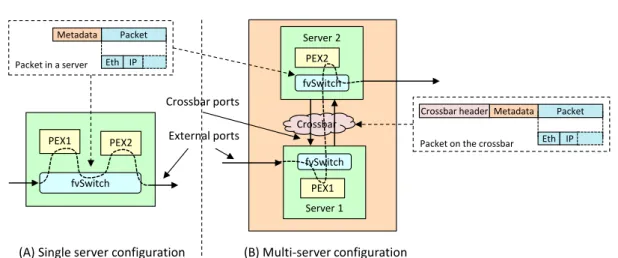
The idea is to distribute the PEX across multiple servers and to transform the fvSwitch into a distributed module, although, from an external view, the system still appears as an unique network device, as shown in Figure 1.8(b) (for instance, VNFs do not notice any difference with respect to the case in which a FROG node is actually a single server). In particular, the system is made up of a cluster of servers connected through an high speed network (currently a 10Gbps switched network) with no external access, namely theFROG crossbar. Each physical port of the server
can then be marked either asexternal orcrossbar. The former is a port visible from
the outside world, and can be eitheraccess (i.e., connected to the end users) orcore
(i.e., connected to the Internet); the latter is instead a port used to connect the server with the rest of the cluster.
Each PEX has a number that identifies univocally the server where it is executed, hence each fvSwitch knows exactly the server responsible for the next processing step. To facilitate the processing in the next server traversed by a packet, the identifier of the next PEX is added to the metadata; then, both packet and metadata
1.6 – FROG and the NFV model PEX1 fvSwitch PEX2 Server 2 Crossbar PEX2 fvSwitch Server 1 PEX1 fvSwitch External ports Crossbar ports
(A) Single server configuration (B) Multi-server configuration
Packet Metadata Eth IP Packet in a server Packet Metadata Eth IP Packet on the crossbar
Crossbar header
Figure 1.8: Single vs. multi-server architecture.
are encapsulated into an additional Ethernet header10 and sent on the crossbar,
which will deliver the packet to the server where the target PEX is running. A packet that is received through a crossbar port is not classified again by the fvSwitch, which simply copies it in the buffer associated with the target PEX, as written in the metadata.
Furthermore, the output port selected for a given packet could be physically in-stalled in another server. In this case the packet (enriched with the proper metadata and encapsulated in the crossbar header) is sent to the target server, which will send it on the network through the correct output port.
1.6
FROG and the NFV model
Table 1.1: NFV vs FROG
NFV FROG
Execution model One VNF per VM, multiple VMs per player Multiple VNF per PEX, one PEX per player
Virtualization environment Full fledged VM PEX executed inside Docker container
Network interfaces towards VNFs Virtualized or paravirtualized network interface cards Designed and optimized for the NFV environment
Service order No assumptions Src end user→Generic players→Dst end user
Although FROG looks like a possible instantiation of the NFV paradigm [43], there are some important differences between the two proposals, which are summa-rized in Table 1.1 and discussed in the remainder of this section.
First, NFV defines a different virtualization environment (i.e., virtual machine) per VNF, while FROG runs all the VNFs belonging to the same player into a single
10The MTU on the crossbar interfaces has been configured appropriately to exceed the traditional
1 – A scalable and massively multi-tenant platform for user-oriented network services
execution environment called PEX. This choice originates from performance reasons and it is intended to reduce the pressure that the high number of expected PEX (and hence players) poses to our system, which could increase even further in case each VNF would require its own PEX. For instance, while the zero-copy mechanism cannot be implemented to move packets between PEX, in order to guarantee traffic isolation among players, it is considered reasonable within the same PEX, which executes VNFs that belong to the same players.
Second, as discussed in Section 1.5.3, in order to support thousands of (active) players at the same time, a PEX is not a full fledged virtual machine (as indicated by NFV), whose requirements in terms of memory and CPU would be too onerous. It is instead a process executed inside a Docker container, which is a lightweight form of virtualization that exploits some features of the Linux kernel to provide resources isolation and limitation.
Another important difference is the nature of the interface between the PEX and the underlying virtual switch. In fact, PEX features a dedicated communica-tion primitive toward the fvSwitch that defines a single (and very optimized)
com-munication channel to send/receive all the traffic, while VNFs executed in virtual machines access to network packets through virtualized or paravirtualized network interfaces cards.
Finally, NFV does not make any assumption on which is the next VNF that has to process a packet. Instead FROG has a well defined service order, and then the fvSwitch is optimized for this specific case; as shown in Section 1.7, this results in reasonable performance of FROG even with a huge number of concurrent VNFs.
1.7
Experimental results
A prototype of FROG was installed on a workstation with 32 GiB of memory, CPU Intel i7-3770 @ 3.40 GHz (four cores plus hyperthreading), Ubuntu 12.10, kernel 3.5.0-17-generic (64 bits), which was equipped with a Silicom dual port 10Gbps Ethernet NIC, based on the the Intel X540 controller and managed by the DNA driver. We also implemented a distributed version of FROG, made up of two of the above machines. In all tests, an entire core was dedicated to the fvSwitch, while PEX have been distributed among the remaining cores. Each test lasted 100 seconds and was repeated 10 times, then results were averaged.
Graphs representing the maximum throughput are provided with a bars view that reports the throughput in millions of packets per second, and a points-based representation that reports the throughput in Gigabit per second. Instead, latency measurements are based on thegettimeofdayUnix system call and include only the
time spent by packets in the FROG node, without the time needed to send/receive data on the network.
1.7 – Experimental results
1.7.1
Single server
In order to provide a concrete demonstration of the scalability of our framework , this section evaluates the maximum throughput that can be obtained with a single FROG node executing a growing number of PEX, and the latency introduced by the node itself in the same conditions.
During the tests, FROG has one physical port connected to a traffic generator and another one to a traffic receiver, handling unidirectional traffic such as in Fig-ure 1.8(a). Each packet traverses two PEX, each one running a simple VNF that calculates a signature across the first 64B of the packets11. We repeated the test with
both our PEX implementations in order to compare the performance of the Java PEX with that of the native PEX. Network tiles are defined by MAC addresses. The traffic generator sends packets in a way so that the first one belongs to the tiles associated with PEX 1 and PEX N, the second packet hits PEX 2 and PEX (N-1), and so on. This pattern stresses the fvSwitch that never receives from the network two consecutive packets to be delivered to the same PEX, with a dramatic impact on memory access patterns. Finally, in each test condition, we selected the minimum size of the shared buffers that allowed the system to work without losses in the communications between the fvSwitch and PEX.
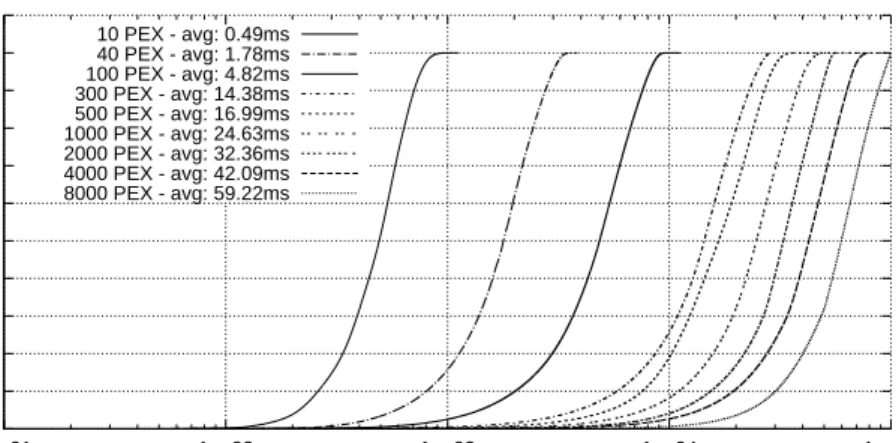
As expected (Figre 1.9), the throughput decreases when increasing the number of PEX in the system. This is mainly due to the loosely localized memory access patterns, as the fvSwitch has to handle packets located in different exchange buffers (hence poor cache locality), which causes also an increase of the CPU TLB misses. However, FROG reaches an impressive result of 6.8Gbps with 700 bytes packets when 8000 PEX are executed. Furthermore, the available bandwidth (i.e., 10Gbps) is saturated in many cases with packets of 700 and 1514 bytes. By comparing Figure 1.9(a)with Figure 1.9(b), it is evident that the native PEX is more efficient than the Java PEX; however, in our opinion the latter performed rather well and its throughput never fell 20% below its competitor.
Figure 1.10 plots the latency introduced by FROG with a growing number of native PEX. As evident, it tends to increase considerably with the number of PEX, reaching an average value of 59.22ms in case of 8000 PEX. The latency introduced by the Java PEX (not reported) is higher in each test case, reaching a worsening of 13% in average in case of 1000 PEX.
While