Departament d’Enginyeria El`
ectrica
Doctoral Thesis
DC current flow controllers for
meshed HVDC grids
Joan Sau-Bassols
Thesis advisors:
Prof. Oriol Gomis-Bellmunt (UPC, Spain) Dr. Eduardo Prieto-Araujo (UPC, Spain) Examination Commitee:
Prof. L. Xu (University of Strathclyde, UK) Dr. D. Montesinos-Miracle (UPC, Spain) Dr. O. Despouys (RTE, France)
Thesis reviewers:
Prof. L. Xu (University of Strathclyde, UK) Dr. O. Despouys (RTE, France)
Departament d’Enginyeria El`ectrica
Centre d’Innovaci´o Tecnol`ogica en Convertidors Est`atics i Accionaments Av. Diagonal, 647. Pl. 2
08028, Barcelona
Copyright © Joan Sau-Bassols, 2019 First printing, May 2019
decide is what to do
with the time that
is given us.”
Pere, N´
uria
and Josep
En primer lloc, vull donar les gr`acies als meus directors: a l'Oriol i a l'Edu, per tot el seu suport i guia tan abans com durant l'etapa del doctorat. L'Oriol amb una gran visi´o global de la feina a fer i l'Edu amb l'ajuda amb tots els dubtes que sortien durant el dia a dia.
Vull tamb´e donar les gr`acies a tots els companys i amics del CITCEA, segurament me'n deixar´e uns quants, per`o els ho agraeixo a tots i totes. Voldria agrair en primer lloc a l'Agust´ı amb qui vaig comen¸car a treballar durant el PFC. Despr´es a tots els companys i amics del grup: Marc, Ricard, Enric, Carlos, Pepe, Ona per compartir tantes bones estones. Tamb´e a les ´
ultimes incorporacions: Jie, Mois´es, Jovana, Lu´ıs, Saman, Josep, Jaume, etc. A la gent d'energia: M`onica, Paco, Pau, Pol, Edu, ´Ingrid i Francesc. A les persones de l'`area de mecatr`onica: Marc Llonch, Dani, Cristian, Jos´e, Tom`as, Gabri, Carlos, Maci`a i Pablo. A la gent de gesti´o (Anna, David, Maria i abans en Jordi) i als altres professors (Daniel, Sam, Andreas, Toni i Roberto) per donar-me l'oportunitat d'estar al CITCEA. Vull donar les gr`acies als companys que ja no estan al centre per´o que han estat molt presents durant aquesta etapa, en especial en Miquel, Xavi, H´ector i Andreu. I would also like to thank Dr. Roberto Alves and Dr. Alireza Nami for giving me the opportunity to work in the ABB CRC of V¨aster˚as during my PhD mobility. I want to thank also Marta, Federico, Konstantina, Vagelis, Haofeng, Karlotta and Yuhei for making my stay really enjoyable.
I would like to thank also Dr. Oliver Cwikowski, Dr. Bin Chang and Prof. Mike Barnes for the fruitful research collaboration in integrating current flow controllers with DC circuit breaker and allowing me to include it in the thesis document.
Vull tenir un record especial pel Dr. Joan Al·les, pel seu inter`es inq¨ uesti-onable i amistat durant aquests anys.
Vull agrair a tota la colla d'amics de Barcelona amb qui hem compartit molts sopars i espero que continuem aix´ı: Arnau, H´ector, Marc Juli`a, Xavi, Joan, Cesc, Marc Rius, Judit, Jordi, M´ıriam i Carles.
No podria acabar sense donar les gr`acies a les companyes de pis durant aquests anys: N´uria, Ariadna, Aina i Emma, per les bones estones compar-tides.
Vull agrair especialment a la colla d'amics de tota la vida pel seu suport i amistat que espero que duri molts anys: Adri`a Coll, Adri`a Roca, Gerard,
de l'angl`es que segur que han millorat i molt la tesi.
Finalment i el m´es important, vull donar les gr`acies a tota la meva fam´ılia pel seu suport durant tots aquests anys: Gemma, Albert, Cristina, Anna, Carme, Agust´ı, Maria `Angels i Santi. I en especial, a l'avi Josep, que cada cap de setmana em demanava com portava la tesi, a la meva germana, N´uria, i als meus pares, Pere i Montse, per la seva ajuda incondicional sempre que ho he necessitat i per animar-me en els moments dif´ıcils.
nya and CITCEA through a FI-DGR grant from the Government of Cata-lonia. Also, the author has received suport from other entities:
Spanish Ministry of Economy and Competitiveness under the projects ENE2013-47296 and ENE2015-67048.
ABB Corporate Research Center (CRC), V¨aster˚as, Sweden.
EIT InnoEnergy PhD School.
Ag`encia de Gesti´o d'Ajuts Universitaris i de Recerca (AGAUR).
Meshed High Voltage Direct Current (HVDC) grids are seen as a solution to transmit and exchange high amounts of power across long distances with high levels of flexibility and redundancy. Also, they can be especially suitable for integrating offshore energy resources such as offshore wind power.
This thesis focuses on the DC Current Flow Controllers (CFC) for meshed HVDC grids. CFCs are being thought as power electronics based devices that may be installed in future meshed HVDC grids to aid in the current flow regulation. The concept is similar to Flexible Alternating Current Trans-mission Systems (FACTS) but applied to HVDC grids.
Firstly, an overview of the different CFC concepts found in the literature is presented. Then, the modelling and control of a DC/DC CFC converter is developed and the benefits of installing it in a meshed HVDC grid are anal-ysed. The functionality of the previous CFC is also integrated into a DC Circuit Breaker (DCCB), in order to have a single device with both capabil-ity to interrupt DC faults and provide DC current regulation. Afterwards, an interline DC/DC CFC topology is proposed, which has the advantage of a simplified converter structure. It is validated using dynamic simulations and a prototype is built and tested in a meshed DC grid experimental platform. A single CFC may not be enough to regulate the current flows in complex meshed HVDC grids, thus, this work also considers the concept of Dis-tributed CFCs (DCFC) in a meshed HVDC grid, which are being operated selectively, allowing more flexibility when regulating the current flows.
Also, multiple lines can be connected to a certain HVDC node, therefore, the presented CFC is extended to be connected to any number of HVDC lines and so, be able to control the current circulating through any of them. The obtained multi-port CFC is validated using simulations.
Other devices can help to the current regulation in meshed HVDC grids, for example already installed DC/DC converters that adapt the different voltages of the HVDC systems. A transformerless DC/DC topology is anal-ysed in this work and the design of its AC filter addressed.
Finally, taking into account that some HVDC links based on Line Com-mutated Converters (LCC-HVDC) are installed near to potential offshore wind power resources, this work studies the operation and control of a Cur-rent Source Converter (CSC) based tapping station connected in series with the HVDC link to integrate offshore wind power.
Les xarxes d'alta tensi´o mallades en cont´ınua, meshed High Voltatge Di-rect Current (HVDC) grids, es presenten com una soluci´o per transportar grans quantitats d'energia a trav´es de llargues dist`ancies o mitjan¸cant ca-bles submarins amb alts nivells de flexibilitat i redund`ancia. Tamb´e, s´on especialment adequades per la captaci´o d'energia de parcs e`olics marins.
Aquesta tesi se centra en els controladors del flux de corrent,Current Flow Controllers (CFC), per a xarxes HVDC mallades. Els CFC es plantegen com dispositius d'electr`onica de pot`encia que es podrien instal·lar en les futures xarxes HVDC mallades per tal d’ajudar en la regulaci´o dels fluxos de corrent de les l´ınies. Aquest concepte ´es similar als dispositius FACTS (Flexible AC Transmission Systems), per`o aplicat a xarxes HVDC.
Primer, es realitza un recull de les diferents propostes de CFCs a la litera-tura. Despr´es, es modelitza i es dissenya el control d'un convertidor DC/DC CFC i s'analitzen els beneficis d'instal·lar-lo en una xarxa HVDC mallada. La funcionalitat de l’anterior CFC s'inclou en els interruptors de cont´ınua, DC Circuit Breakers (DCCB), per tal de tenir un dispositiu amb capacitat d'interropre faltes DC i tamb´e controlar corrents. A continuaci´o, es proposa una topologia de CFC simplificada, que es valida per mitj`a de simulacions i se'n construeix un prototip que es prova experimentalment al laboratori.
Un ´unic CFC pot no ser suficient per a controlar els fluxos de corrent en xarxes HVDC mallades d'una certa complexitat. ´Es per aix`o, que tamb´e s’introdueix el concepte de CFCs distribu¨ıts en diferents nodes de la xarxa i que s'operen de forma selectiva.
V`aries l´ınies HVDC poden estar connectades a un node, ´es per aix`o, que la topologia de CFC anteriorment presentada s'actualitza per tal de poder ser connectada a un nombre qualsevol de l´ınies. La topologia multi-port obtinguda es valida per mitj`a de simulacions.
Altres dispositius que poden ajudar a controlar els fluxos de corrent s´on els propis convertidors DC/DC que s'encarreguen d'adaptar la tensi´o dels sistemes HVDC. S'analitza un convertidor DC/DC sense transformador AC i es realitza un disseny del seu filtre AC.
Finalment, algunes de les l´ınies HVDC basades en tecnologia Line Com-mutated Converter (LCC) es troben a prop de zones amb energia e´olica potencial. Per aquest motiu, s'estudia l'operaci´o i control d'un convertidor Current Source Converter (CSC) que actua com una estaci´o detapping per tal d'injectar l'energia d'un parc e`olic mar´ı a la l´ınia LCC-HVDC.
List of Figures xix
List of Tables xxix
Nomenclature xxxi
1 Introduction 1
1.1 Current context . . . 1
1.2 HVDC grids . . . 4
1.3 Objectives and scope . . . 6
1.4 Work and activities during the thesis period . . . 10
1.5 Thesis outline . . . 12
2 Review of power flow controllers or current flow controllers 15 2.1 Parallel-connected CFCs . . . 15
2.2 Series-connected CFCs . . . 16
2.2.1 Series variable resistors . . . 17
2.2.2 AC/DC converters . . . 17
2.2.3 DC/DC converters . . . 19
2.2.4 DC circuit breakers and CFCs . . . 24
2.3 Series-parallel-connected CFCs . . . 25
2.4 Conclusions . . . 27
3 Modelling and control of an interline current flow controller for meshed HVDC grids 29 3.1 Introduction . . . 29
3.2 Model derivation . . . 29
3.2.1 DC grid under study . . . 29
3.2.2 CFC under study . . . 29
3.2.3 Operation principle . . . 32
3.2.4 CFC average model . . . 35
3.3 Steady-state analysis . . . 36
3.3.2 Operational area analysis . . . 42
3.4 Control design of the current controller . . . 43
3.5 Case studies with a current controller . . . 51
3.5.1 Case studies 1-2: simulation results with a 3-terminal grid . . . 51
3.5.2 Case studies 3-4: simulation results with a 5-terminal grid . . . 53
3.6 Coordinated control design of the voltage and current controller 58 3.7 Case studies with a current controller and voltage controller . 63 3.7.1 Case studies 5-7: simulation results with a 5-terminal grid . . . 63
3.8 Conclusion . . . 68
4 Integrated HVDC circuit breakers with current flow control capa-bility 71 4.1 Introduction . . . 71
4.2 DC circuit breakers with current flow control capability . . . 72
4.3 Proactive hybrid circuit breaker . . . 72
4.4 Current flow controller . . . 74
4.4.1 CFC modelling . . . 76
4.5 Integrated LCS with CFC capability . . . 76
4.5.1 State-space analysis of LCS/CFC commutation . . . . 79
4.6 PSCAD modelling . . . 82
4.7 Simulink modelling . . . 84
4.7.1 Linearised state-space . . . 84
4.7.2 CFC switching model . . . 86
4.8 LCS/CFC control design methodology . . . 86
4.9 Simulation results . . . 88
4.9.1 Normal operation of the LCS/CFC . . . 88
4.9.2 Protection simulations . . . 89
4.10 Conclusions . . . 92
5 Series interline DC/DC current flow controller for meshed HVDC grids 93 5.1 Introduction . . . 93
5.2 Series interline current flow controller . . . 94
5.2.1 CFC topology . . . 94
5.2.2 Extended CFC topology for all current flows . . . 95
5.2.3 Implementation methodology for the extended CFC topology for all current configurations . . . 97
5.3 CFC modelling . . . 97
5.3.1 Operating principle . . . 97
5.4 Comparison between the proposed CFC topology and the du-al H-bridge . . . 101
5.4.1 Switch requirement for different current configurations 101 5.4.2 Unidirectional current flow topologies . . . 103
5.5 Operation of the extended CFC topology . . . 105
5.5.1 Transitions between CFC modes . . . 105
5.5.2 Modulation strategy . . . 106
5.6 CFC protection under DC fault conditions . . . 108
5.7 5-terminal meshed HVDC grid for CFC validation . . . 111
5.7.1 5-terminal meshed HVDC grid modelling . . . 111
5.8 CFC control design . . . 112
5.9 Simulations results . . . 115
5.9.1 CFC start-up . . . 115
5.9.2 CFC increasing, nulling and invertingI51 . . . 115
5.9.3 CFC increasing, nulling and invertingI41 . . . 117
5.9.4 CFC operation during power flow change . . . 117
5.10 Experimental validation . . . 121
5.10.1 System description . . . 121
5.10.2 Control of the converters . . . 124
5.10.3 Experimental results . . . 124
5.11 Conclusion . . . 129
6 Selective operation of distributed current flow controller devices for meshed HVDC grids 131 6.1 Introduction . . . 131
6.2 Distributed CFC concept . . . 131
6.3 Modelling of the CFCs and the meshed HVDC grid . . . 133
6.3.1 CFC modelling . . . 133
6.3.2 Meshed HVDC grid modelling . . . 134
6.4 Steady-state analysis . . . 136
6.4.1 Analysis methodology . . . 136
6.4.2 Methodology example . . . 136
6.4.3 Case study 1: 3-terminal meshed grid with all possible CFCs . . . 139
6.4.4 Case study 2: 7-terminal meshed grid with three dif-ferent CFCs . . . 144
6.5 Design aspects of the DCFC devices and effect on the
opera-tional area . . . 150
6.5.1 Comparison of the operational area of the system using DCFCs or a 2B-CFC located in one node . . . 151
6.5.2 Losses consideration . . . 154
6.6 Operation and control of the DCFCs . . . 155
6.7 Dynamic simulations . . . 156
6.8 Conclusions . . . 160
7 Multi-port interline current flow controller for meshed HVDC grids 161 7.1 Introduction . . . 161
7.2 Multi-port current flow controller . . . 161
7.3 Converter modelling . . . 163
7.3.1 Operating principle . . . 163
7.3.2 Modulation and control strategy . . . 165
7.3.3 Average model . . . 167
7.4 Case study: simulations of a 5-port CFC . . . 168
7.4.1 System description . . . 168
7.4.2 Simulation results . . . 171
7.5 Conclusion . . . 174
8 Filter design of a transformerless DC/DC converter based on the autotransformer concept for the interconnection of HVDC grids 175 8.1 Introduction . . . 175
8.2 DC/DC autotransformer concept . . . 176
8.3 Transformerless DC/DC converter . . . 178
8.3.1 AC filter purposes . . . 179
8.4 Modelling of the TL converter . . . 180
8.4.1 Description of the converter . . . 180
8.4.2 Detailed model . . . 180
8.4.3 Average model . . . 181
8.4.4 Simplified model . . . 182
8.5 Control of the converter . . . 183
8.6 Filter design . . . 185
8.6.1 Limit 1: active power transfer between voltage sources 186 8.6.2 Limit 2: apparent power of the MMCs . . . 186
8.6.3 Limit 3: modulation limit of the MMCs considering the voltage ripple in the submodules . . . 187
8.6.4 Steady-state analysis . . . 190
8.7 Dynamic simulations . . . 192
8.7.1 Model comparison: filter made of a capacitor Cm and an inductor Lm . . . 192
8.7.2 Detailed model results: filter made of a capacitor Cm 194 8.8 Losses estimation . . . 194 8.9 DC fault considerations . . . 197 8.10 Conclusion . . . 197 9 Conclusions 203 9.1 General conclusions . . . 203 9.2 Contributions . . . 204 9.3 Future work . . . 205 Bibliography 207 A Operation and control of a current source converter series tap-ping of an LCC-HVDC link for integration of offshore wind power plants 221 A.1 Introduction . . . 221
A.2 System description . . . 223
A.3 System modelling . . . 223
A.3.1 LCC-HVDC transmission system . . . 223
A.3.2 Current source converter . . . 226
A.3.3 Offshore wind power plant . . . 226
A.4 System control design . . . 229
A.4.1 LCC-HVDC transmission system . . . 229
A.4.2 Current source converter . . . 231
A.4.3 Wind turbine . . . 231
A.5 Power reduction algorithm . . . 235
A.5.1 Steady-state analysis during DC current reduction . . 235
A.5.2 Considerations on system reliability . . . 237
A.5.3 Proposed Power Reduction Algorithm (PRA) . . . 237
A.6 Dynamic simulations . . . 239
A.6.1 Start-up and DC current reduction without PRA . . . 240
A.6.2 Start-up and DC current reduction with PRA . . . 241
A.6.3 Communication loss . . . 244
A.7 Conclusions . . . 247
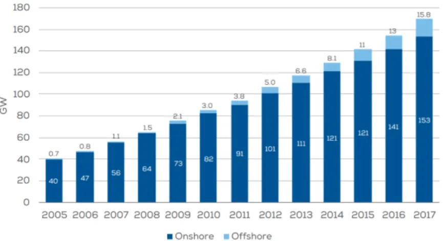
1.1 Cumulative wind installations onshore and offshore in the EU.
Total: 168.7 GW. Source: WindEurope [3]. . . 2
1.2 Cumulative installations onshore and offshore by country. To-tal: 168.7 GW. Source: WindEurope [3] . . . 3
1.3 DolWin1 offshore wind platform. Source: ABB [12]. . . 4
1.4 Global overview of HVDC systems including point-to-point links and meshed HVDC grids used to integrate offshore wind power and interconnect different countries. . . 7
2.1 CFC concepts. (a) Parallel-connected. (b) Series-connected. (c) Series-parallel-connected. . . 15
2.2 Series variable resistor. . . 17
2.3 AC/DC converters. . . 18
2.4 Thyristor-based current flow controller. . . 18
2.5 IGBT-based current flow controller. . . 19
2.6 DC/DC converter based CFC. . . 20
2.7 Dual H-bridge. (a) General topology. (b) Simplified topology. 20 2.8 Interline DC/DC topology. (a) General topology. (b) Simpli-fied topology. . . 21
2.9 Enhanced interline DC/DC topology. . . 21
2.10 Series interline DC/DC unidirectional CFC. (a) Structure when the currents of line 1 and 2 are going out the device. (b) Structure when the currents of line 1 and 2 are going in the device. . . 22
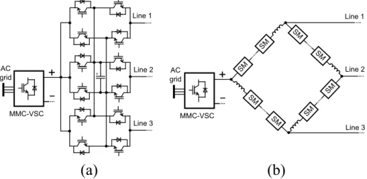
2.11 CFCs based on MMC structures. (a) CFC with two 3-phase MMCs in F2F configuration with an isolation transformer. (b) CFC based on 5 MMC arms without AC transformer. . . 23
2.12 Multi-port CFCs. (a) Multi-port topology of the Dual H-bridge. (b) Multi-port polygon-shape CFC based on MMC arms. . . 24
2.13 Integrated DCCB with CFC capability. . . 26
3.1 3-terminal DC grid with CFC located in node 1. . . 30 3.2 CFC topologies. (a) Dual H-bridge CFC. (b) Simplified dual
H-bridge CFC. . . 30 3.3 Pairs A, B, C and D. . . 33 3.4 E,Ic,V1 and V2 working with pair A. . . 35
3.5 3-terminal DC grid with a CFC average model in node 1. . . 37 3.6 Line and node currents. . . 39 3.7 Node voltages and CFC capacitor voltage. . . 40 3.8 Node powers and CFC power. . . 41 3.9 Operation area. . . 43 3.10 3-terminal HVDC grid system model. . . 44 3.11 Bode diagram representation of the open-loop transfer
func-tion G(s) . . . 47 3.12 Line current control scheme. . . 48 3.13 Bode diagram representation of the controller transfer
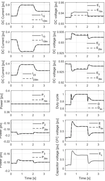
func-tion K(s) . . . 48 3.14 Bode diagram representation of transfer functionKS(s) . . . 49 3.15 Frequency and time response of the closed loop transfer function 50 3.16 Frequency response of the transfer functionGK(s) . . . 51 3.17 Simulation resuls of Case study 1: Line currents, node
vol-tages, node powers, duty cycle, CFC voltage and capacitor voltage. . . 54 3.18 Simulation results of Case study 2: Line currents, node
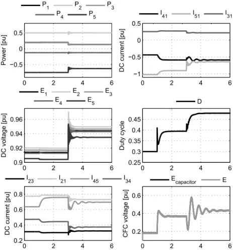
vol-tages, node powers, duty cycle, CFC voltage and capacitor voltage. . . 55 3.19 5-terminal DC grid with the CFC in node 1. . . 56 3.20 Simulation results of Case study 3: System variables under a
power step change. . . 57 3.21 Simulation results of Case study 4: System variables under a
converter terminal outage. . . 58 3.22 Control scheme with an inner voltage controller and an outer
current controller. . . 59 3.23 Block diagrams of the transfer functions Govershoot(s) and
Gaction. . . 61
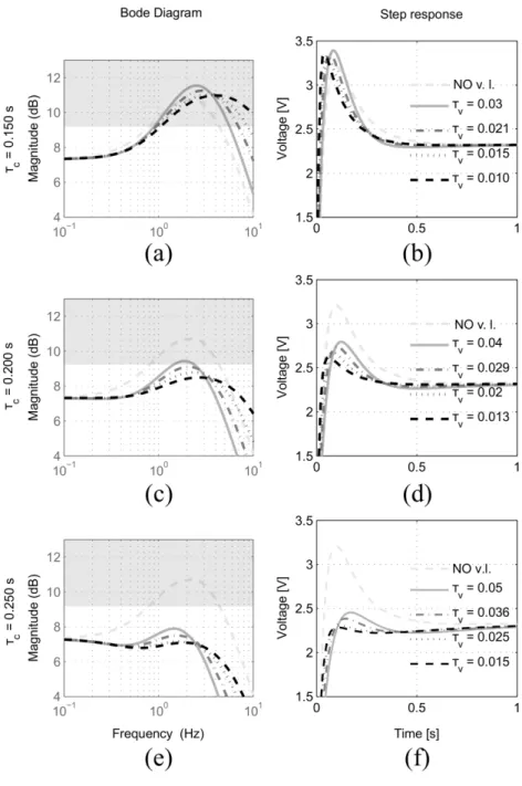
3.24 Frequency response ofTc(s) (left column) andGaction(s) (right
columns) for different τc and τv. . . 64
3.25 Frequency and time step response ofGovershoot(s) for different τc and τv. . . 65
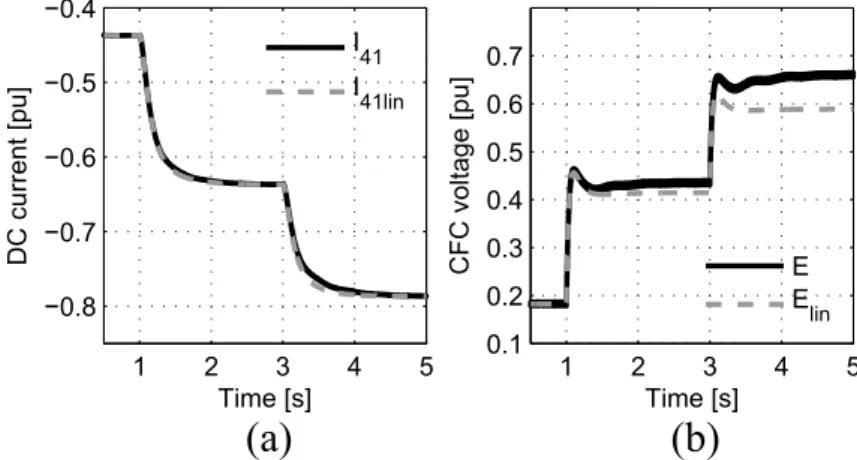
3.26 Comparison between the linearised and detailed model. (a) DC current of line 41. (b) CFC voltage. . . 66
3.27 Comparison between different CFC control schemes. (a) DC current of line 41. (b) CFC voltage. . . 67 3.28 Comparison between different CFC control schemes. (a) DC
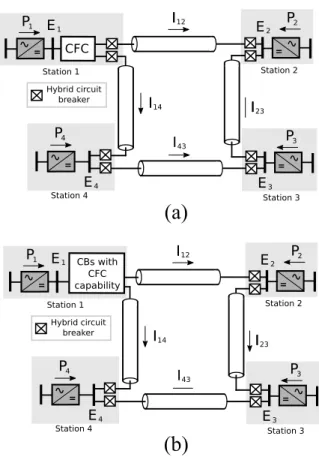
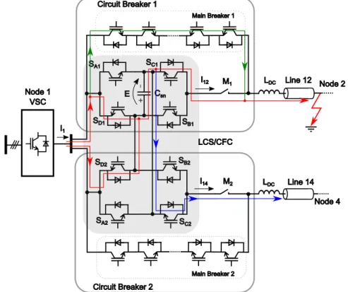
current of line 41. (b) CFC voltage. . . 69 4.1 Meshed HVDC grid under study. (a) CFC and CBs in a
se-parate design. (b) Proposed integrated CBs with CFC func-tionality. . . 73 4.2 The proactive hybrid circuit breaker [59]. . . 73 4.3 Dual H-bridge CFC topology. . . 75 4.4 (a) LCS structure. (b) LCS structure with CFC capability. . 77 4.5 LCS interconnected with CFC capability. Current flow
consi-dering a fault on line 12 with the LCS/CFC switches in OFF state and the main breakers turned OFF. . . 77 4.6 Shows the current flowpath within the LCS/CFC once the
Main Breaker 1 is turned ON. . . 78 4.7 Equivalent circuit during commutation. . . 79 4.8 Verification of commutation analysis for combined and
sepa-rate cases. PSCAD results and calculations. . . 81 4.9 Commutation process with LCS/CFC. Partner line current
=Ip. PSCAD Results. . . 82
4.10 Full PSCAD simulation model. . . 83 4.11 Control structure of the MMC system. . . 84 4.12 Equivalent model of the 4-terminal HVDC system with CFC
used for linearisation. . . 85 4.13 Equivalent model of the 4-terminal HVDC system with the
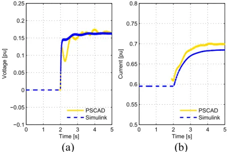
CFC switching and PI cable models. . . 87 4.14 Control scheme of the CFC. . . 88 4.15 Comparison of normal operation case study results from
MAT-LAB and PSCAD simulations. (a) LCS/CFC voltage VLCS.
(b) Current I12. . . 89
4.16 Fault Current Comparison for each case. Total fault current (solid lines). Primary branch current (dashed lines) - PSCAD Results. . . 91 4.17 Comparison of combined and separate cases. . . 91 5.1 Proposed CFC topology. (a) Two currents entering and one
going out. (b) Two currents going out and one entering. . . . 94 5.2 Extended CFC topology able to operate with current
5.3 Extended CFC topology for all current configurations. . . 96 5.4 CFC layout of the extended topology taking advantages of
the anti-parallel diodes. . . 97 5.5 CFC operation in mode 2 considering constant DC currents
through lines A and B. (a) CFC voltage. (b) Voltage across switch S1. (c) Current through the capacitor. (d) Voltage
across switchS2. . . 100
5.6 Average model of the CFC considering current configurations 1 and 2. . . 101 5.7 Average model of the extended CFC topology for all the
cur-rent configurations. . . 102 5.8 Comparison between the presented topology and the dual
H-brigde CFC for different groups of current configurations. . . 104 5.9 Transition scheme between CFC modes 4, 6 and 2 considering
IA>0. . . 106
5.10 Layout of the extended CFC topology for all current configu-rations considering transitions between modes 2, 4 and 6 with
IA>0. . . 107
5.11 Modulation strategy for the extended CFC topology for CFC modes 2, 4, 6. . . 109 5.12 Modulation and switch selection logic for the extended CFC
topology considering modes 2, 4 and 6. . . 110 5.13 Scheme of the CFC and the protection equipment considering
a DC fault in Cable 1. . . 110 5.14 5-terminal meshed HVDC grid used for CFC validation. . . . 112 5.15 DC cable model with parallel series branches. . . 112 5.16 CFC control scheme with a inner voltage loop and an outer
current loop. . . 114 5.17 CFC start-up procedure. (a) CFC currents. (b) Current
through the CFC capacitor. (c) CFC duty cycle. (d) Ap-plied mean voltages by the CFC. . . 116 5.18 CFC increasing, nulling and invertingI51. (a) CFC currents.
(b) DC grid currents. (c) CFC voltage. (d) Node voltages. (e) CFC duty cycle. (f) Node powers. (g) Applied mean voltages by the CFC. (h) Currents through switchesS7 and S8. . . 118
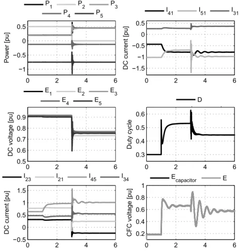
5.19 CFC increasing, nulling and invertingI41. (a) CFC currents.
(b) DC grid currents. (c) CFC voltage. (d) Node voltages. (e) CFC duty cycle. (f) Node powers. (g) Applied mean voltages by the CFC. (h) Currents through switchesS1 and S2. . . 119
5.20 CFC operation during a power change in node 5. (a) CFC currents. (b) DC grid currents. (c) CFC voltage. (d) Node voltages. (e) CFC duty cycle. (f) Node powers. . . 120 5.21 Scheme of the experimental 3-terminal meshed DC grid with
a 3-port CFC in the laboratory. . . 121 5.22 Image of the experimental platform, including the CFC and
the three VSCs. . . 122 5.23 Detail of the CFC converter. . . 122 5.24 Control scheme of the experimental 3-port CFC. . . 124 5.25 Experimental results considering a ramped change of the duty
cycle of the CFC in open-loop: Line currents and CFC voltage.125 5.26 Experimental results considering a constant duty cycle ofD2 =
0.5 in open-loop: Current I12p and voltages applied by the
CFC on the lines. . . 126 5.27 Experimental results considering a voltage step change in
closed-loop using the voltage controller: Line currents and CFC voltage. . . 127 5.28 Experimental results considering a current step change in
closed-loop using the voltage and current controllers: Line currents and CFC voltage. . . 128 5.29 Experimental results with current control and changes in the
power of the nodes: Line currents and CFC voltage. . . 128 5.30 Experimental results considering a current step change in
closed-loop using the voltage and current controllers: Line currents of the positive and negative pole and CFC voltage. . 129 6.1 n-terminal meshed HVDC grid. (a) 2B-bridge CFC located
in node 1. (b) DCFCs in several nodes. . . 132 6.2 Series interline DC/DC CFC for unidirectional current flow.
(a) Two currents entering the device. (b) Two currents going out of the device. . . 133 6.3 Average model of the unidirectional CFC. . . 134 6.4 Model of then-terminal meshed HVDC grid with three CFC
average models. . . 135 6.5 3-terminal meshed HVDC grid with a CFC. (a) Scheme of the
meshed grid. (b) Average model of the unidirectional CFC in node 1. . . 137 6.6 Model of a 3-terminal meshed HVDC grid with all the possible
6.7 Current variation and voltage requirement using different CFCs. (a) Current variation with CFC 1A. (b) Voltage requirement with CFC 1A. (c) Current variation with CFC 2C. (d) Volta-ge requirement with CFC 2C. (e) Current variation with CFC 3A. (f) Voltage requirement with CFC 3A . . . 140 6.8 Current variation range for different CFCs. . . 142 6.9 Current variation and sensitivity analysis for different CFCs.
(a) I12 variation with respect to CFC voltage. (b) I12
sen-sitivity with respect to CFC voltage. (c) I13 variation with
respect to CFC voltage. (d) I13 sensitivity with respect to
CFC voltage. (e) I23 variation with respect to CFC voltage.
(f) I23 sensitivity with respect to CFC voltage. . . 143
6.10 Distributed CFCs in a 7-terminal meshed HVDC grid. (a) 7-terminal meshed HVDC grid scheme. (b) Model of CFC 5A. (c) Model of CFC 3A. (d) Model of CFC 5B. . . 146 6.11 Current variation and voltage requirement for different CFCs.
(a) Current variation with CFC 5A. (b) Voltage requirement of CFC 5A. (c) Current variation with CFC 3A. (d) Voltage requirement with CFC 3A. (e) Current variation with CFC 5B. (f) Voltage requirement with CFC 5B. . . 148 6.12 Current variation and sensitivity analysis for different CFCs.
(a) I34 with respect to CFC voltage. (b) I34 sensitivity with
respect to CFC voltage. (c) I35with respect to CFC voltage.
(d) I35 sensitivity with respect to CFC voltage. (e) I45 with
respect to CFC voltage. (f) I45 sensitivity with respect to
CFC voltage. (g) I57 with respect to CFC voltage. (h) I57
sensitivity with respect to CFC voltage. . . 149 6.13 Distributed CFCs in the 3-terminal meshed HVDC grid. (a)
Converter structure of each DCFC. (b) Scheme showing the connection of each DCFC to the meshed HVDC grid. . . 150 6.14 2B-CFC located in node 1 in the 3-terminal meshed HVDC
grid. (a) Converter structure of the 2B-CFC topology able to operate with all current flows. (b) Scheme showing the connection of the 2B-CFC in node 1 to the meshed HVDC grid.151 6.15 Increase in the operational area of the system due to the
2B-CFC located in node 1 of Fig. 6.14. . . 152 6.16 Increase in the operational area of the system due to the
Dis-tributed CFCs of Fig. 6.13. . . 153 6.17 Control scheme of each DCFC with a voltage loop and a
6.18 Flowchart of the algorithm that governs the DCFCs. . . 157 6.19 Simulation results of the 3-terminal HVDC grid without CFC
(dashed lines) and with the three DCFCs (solid lines). (a) Line currents. (b) Node powers. (c) Node voltages. . . 158 6.20 Simulation results of the 3-terminal HVDC grid with three
DCFCs. (a) CFC voltages of the DCFCs. (b) Bypass and duty cycle signals of the DCFC 2A and 3A. . . 159 7.1 Scheme of the multi-port CFC topology located in Node 1
and connected to n−1 lines. (a) DC currents circulating from Node 1 to the other lines. (b) DC currents circulating to Node 1 coming from the other lines. . . 162 7.2 Modulation strategy applied to then-port CFC. . . 166 7.3 Modulation implemented with logic blocks for a n-port CFC. 167 7.4 Average model of then-port CFC made ofn−1 voltage
sour-ces and n−2 circuits with a capacitor and n−1 current sources in parallel. . . 168 7.5 Scheme of a 5-terminal meshed HVDC grid with two 5-port
CFCs considered for the dynamic simulation. (a) 5-terminal HVDC grid (b) Scheme of the 5-port CFC of the positive pole. (c) Scheme of the 5-port CFC of the negative pole. . . 169 7.6 Simulation results. (a) Node voltages. (b) Node powers. (c)
First set of line currents in the positive pole. (d) First set of line currents in the negative pole. (e) Second set of line currents in the positive pole. (f) Second set of the line currents in the negative pole. . . 172 7.7 Simulation results. (a) Voltages of the capacitors in the CFC
on the positive pole. (b) Voltages of the capacitors in the CFC on the negative pole. (c) Duty cycles of the CFC in the positive pole. (d) Duty cycles of the CFC in the negative pole. 173 8.1 DC/DC interconnectors. (a) DC/DC transformer. (b) DC/DC
autotransformer. . . 177 8.2 Power distribution inside the DC/DC autotransformer as a
function of the voltage ratio between DC sides,nAT. . . 178
8.3 Scheme of the DC/DC autotransformers based on three-phase MMCs. (a) Topology with an AC transformer as the interface. (b) Transformerless (TL) topology using an AC filter (LC) as the interface. . . 179
8.4 Model of the MMC used in the detailed model of the TL topology. . . 181 8.5 Simplified model of one phase of the AC side of the TL
con-verter obtained from the average model of the MMCs and the filter. . . 183 8.6 Equivalent model of one phase leg of the MMC according to
[97]. . . 184 8.7 Simplified model of one phase of the AC side of the TL
con-verter from the control perspective explained in [97]. . . 185 8.8 Equivalent voltage ripple of the upper arm for different Cm
compared with the voltage reference of the same arm VU1. . . 188
8.9 Equivalent voltage ripple of the lower arm for different Cm
compared with the voltage reference of the same arm VL1. . . 189
8.10 Steady-state analysis of the filter variables considering nomi-nal power. (a) Resonance frequency of the filter fres. (b)
RMS value of the AC current through the filter. (c) RMS value of the AC component of the voltage across the capacitor.191 8.11 Variation ofCm for a constant value of theXtotal=XLim as
a function of Lm. . . 192
8.12 Simulation results showing the comparison between the TL topology models: detailed, average and simplified. (a) The-venin voltage of phasea Vtha. (b) AC current through phase
a of the filter Ia. (c) Voltage of phase a across the capacitor
of the filter VCa. (d) Voltage of phase a across the inductor
of the filterVLa. . . 193
8.13 Simulations results of the TL topology using the detailed mo-del. (a) HV side power, LV side power and Transformed power. (b) HV side voltage, LV side voltage, DC voltage of MMC 2 and DC voltage of MMC 1. (c) Active power and reactive power of MMC 2. (d) DC voltage ripple of the submodules of the upper arm a of MMC 2. . . 195 8.14 Simulations results of the TL topology considering the
detai-led model. (a) AC voltages of MMC 2 at the point of the filter connection. (b) AC currents circulating through the fil-ter. (c) Voltages across the capacitor in the filfil-ter. (d) Arm currents of the upper arms of MMC 2. . . 196 8.15 Losses estimation of the TL topology considering the
appro-ach with a capacitor as the AC filter. (a) Losses in the semi-conductors of MMC 1. (b) Losses in the semisemi-conductors of MMC 2. (c) Total losses of the TL topology. . . 198
A.1 Undersea LCC-HVDC transmission links in Northern Europe 222 A.2 System scheme . . . 223 A.3 Two-level CSC with the AC capacitors . . . 226 A.4 Single line and control scheme of the CSC . . . 227 A.5 Wind turbine control scheme . . . 228 A.6 LCC transmission system control scheme . . . 230 A.7 VDCOL law . . . 230 A.8 Wind turbine characteristic . . . 232 A.9 Wind turbine and generator side VSC control scheme . . . . 233 A.10 Grid side VSC control scheme . . . 234 A.11 Relation P−Idc for different voltagesvcq . . . 236
A.12 Relation vcq−Idc for different active powersP . . . 237
A.13 Wind turbine control scheme with the proposed power reduc-tion algorithm . . . 239 A.14 Simulation results for CSC start-up and DC current reduction
without PRA: LCC-HVDC and CSC variables . . . 242 A.15 Simulation results for CSC start-up and DC current reduction
without PRA: Wind turbine and VSCs variables . . . 243 A.16 Simulation results for CSC start-up and DC current reduction
with PRA: LCC-HVDC and CSC variables . . . 245 A.17 Simulation results for CSC start-up and DC current reduction
with PRA: Wind turbine and VSCs variables . . . 246 A.18 Simulation results during loss of communication: LCC-HVDC
and CSC variables . . . 247 A.19 Simulation results during loss of communication: Wind
3.1 CFC states in positive and negative currents scenarios . . . . 31 3.2 CFC voltages applied for each pair of operation states . . . . 36 3.3 Operational area increase for different maximum CFC voltages 44 3.4 Controllers parameters . . . 50 3.5 3-terminal system parameters . . . 52 3.6 Node parameters for Case study 1 and 2 . . . 52 3.7 5-terminal system parameters . . . 56 3.8 Controllers’ parameters . . . 63 4.1 Circuit Breaker parameters. MB=Main Breaker . . . 74 4.2 Switching states of the CFC . . . 75 4.3 Simulink model parameters . . . 87 4.4 Controller parameters . . . 88 4.5 Comparison of Combined and Separate LCS and CFC desgins 92 5.1 Possible current configurations in a 3-port CFC . . . 95 5.2 Comparison of the required diodes and IGBTs between the
presented topology and the dual H-brigde CFC for different current configurations . . . 102 5.3 Advantages and disadvantages of the proposed CFC and the
dual-H bridge for unidirectional current flow . . . 105 5.4 Switch states during CFC bypass . . . 108 5.5 Cable model parameters . . . 113 5.6 HVDC grid parameters . . . 113 5.7 Control parameters . . . 114 5.8 VSC parameters . . . 123 5.9 DC line parameters . . . 123 5.10 CFC parameters . . . 123 6.1 Case Study 1: System Parameters . . . 141 6.2 CFC current range and current variation capability . . . 145 6.3 Case Study 2: Node Parameters . . . 145 6.4 Case Study 2: Cable Parameters . . . 147
6.5 Limits of the CFC and the meshed HVDC grid . . . 151 6.6 Losses comparison for three different case studies . . . 155 7.1 HVDC grid parameters . . . 170 7.2 CFC parameters . . . 170 8.1 System parameters . . . 200 8.2 Capacitance limits as a function of the AC frequency of the
TL converter . . . 201 A.1 LCC-HVDC parameters . . . 224 A.2 CSC parameters . . . 224 A.3 OWPP parameters . . . 225 A.4 Control parameters . . . 240
2B-CFC Dual H-Bridge CFC ABB ASEA Brown Boveri AC Alternating Current CB Circuit Breaker
CFC Current Flow Controller
CIGR ´E Conseil International des Grands R´eseaux ´Electriques CITCEA Centre d’Innovaci´o en Convertidors Est`atics i Accionaments CL Current Loop
CSC Current Source Converter (self-commutating) DAB Dual Active Bridge
DC Direct Current DCCB DC Circuit Breaker
DCFC Distributed Current Flow Controller DSP Digital Signal Processor
dSPACE Digital Signal Processing and Control Engineering FACTS Flexible Alternating Current Transmission Systems FDCTS Flexible Direct Current Transmission Systems FPC Full Power Converter
GE General Electric GSC Grid Side Converter HCB Hybrid Circuit Breaker HF High Frequency
HV High Voltage
HVDC High Voltage Direct Current HVAC High Voltage Alternating Current IGBT Insulated-Gate Bipolar Transistor IMC Internal Model Control
LCC Line-Commutated Converter LV Low Voltage
MMC Modular Multilevel Converter
NPO Non-Possible Operation OWPP Offshore Wind Power Plant PFC Power Flow Controller
PHCB Proactive Hybrid Circuit Breaker PI Proportional-Integral controller
PMSG Permanent Magnet Synchronous Generator PMSM Permanent Magnet Synchronous Machine PLL Phase Locked Loop
PV Photovoltaic
PWM Pulse Width Modulation RMS Root Mean Square SCR Short Circuit Ratio TL Transformerless
TSO Transmission System Operator UPC Universitat Polit`ecnica de Catalunya VSC Voltage Source Converter
WEC World Energy Council WFC Wind Farm Converter WPP Wind Power Plant
Introduction
1.1 Current context
The European Union (EU) has set a series of ambitious climate and energy targets to fight against climate change. The 2020 targets [1] established three key objectives for the year 2020, which are the 20% reduction in greenhouse gas emissions (from 1990 levels), the commitment that the 20% of the EU energy consumption must come from renewable resources and a 20% im-provement in energy efficiency.
The targets beyond 2020 are even more ambitious, specifically for 2030 are the following ones: the cuts in greenhouse gas emissions are set at 40% with respect 1990 levels, the share in consumption coming from renewable resources is to be increased to 27% and also the efficiency must improve in a 27% [1].
The role of wind generation will be decisive in order to meet the current climate and energy commitments [2]. At the end of 2017, wind energy accounted for the 18% of EU’s total installed power generation capacity [3] and during the same year covered 11.6% of the EU’s electricity demand. Among Wind Power Plants (WPP), offshore installations present a number of benefits compared to the traditional onshore installations. These benefits lie on the availability of higher wind speeds, the possibility to transport larger structures (bigger wind turbines able to extract more wind power) and the fact that some onshore locations are already saturated with older wind turbines.
The cumulative wind power installations from 2005 to 2017 can be seen in Fig. 1.1.
The numbers show that the European installed capacity of wind power was at the end of 2017 168.7 GW and 15.8 GW of those belong to offshore installations [3]. By 2020, the installed wind capacity is expected to reach 204 GW, of which 25 GW will be from offshore.
Fig. 1.1: Cumulative wind installations onshore and offshore in the EU. To-tal: 168.7 GW. Source: WindEurope [3].
are shown in Fig. 1.2. Germany is the leading country in installed capacity, followed by Spain and UK [3].
Offshore Wind Power Plants (OWPP) can be connected to the AC grid using High Votlage Alternating Current (HVAC) or High Voltage Direct Current (HVDC) technologies [4]. The choice between them depends on the economic aspects, which depend in turn on the transmission distance and power rating [4]. In HVAC, there is the need to compensate the impedance of the cables, and this grows with the distance of the transmission at a higher rate than for HVDC. On the other side, HVDC implies a fixed cost for the converter stations. Therefore, there is break-even distance where the HVDC option has a lower price than HVAC. This break-even distance for submarine cables is around 100 km [4].
Among HVDC technologies, there are two commercial options: Line-Commutated Converters (LCC) using thyristors and Voltage Source Con-verters (VSC) employing self-commutating devices [5]. LCC-HVDC trans-mission systems have been the traditional option and possess a high de-gree of reliability and maturity, with many stations interconnecting main-land and ismain-lands. The available power and voltage levels are also higher in LCC-HVDC compared to VSC-HVDC. However, VSC-HVDC seems more suitable to interconnect OWPPs due to the following reasons: active and reactive power can be controlled independently, they can feed passive loads without an AC grid to operate. They also have black-start capability and a reduced footprint compared to LCC-HVDC due to a reduction of the ouput
Fig. 1.2: Cumulative installations onshore and offshore by country. Total: 168.7 GW. Source: WindEurope [3]
filter requirements [6, 7]. This last feature is especially relevant for offshore applications, where the footprint and weight of the converter station play an important role [4].
The latests VSC-HVDC designs based on Modular Multilevel Converters (MMC) [8] employ the cascading of a large number of submodules per arm. This concept allows to handle higher DC voltages by simply adding more submodules and the switching frequency can be reduced while still fulfilling the requirements on harmonic distortion in the output voltage. This fact implies that the losses drop and the converter also has benefits at the manu-facturing stage as it is composed of a number of identical units (submodules) [9].
The world’s first VSC-HVDC for offshore power transmission (BorWin1) was constructed off the coast of Germany in 2009 by ABB. Since then, a number of VSC-HVDC links for the integration of offshore wind power have been constructed successfully offshore in the north of Germany. Three of them have been delivered by ABB (BorWin 1, DolWin 1 and DolWin 2) [10] and the others (BorWin2, SylWin1, HelWin1 and HelWin2) have been handed over to the same customer, TenneT (German-Dutch TSO), by Siemens [11]. An image of the offshore platform of Dolwin 1 is shown in Fig. 1.3.
Fig. 1.3: DolWin1 offshore wind platform. Source: ABB [12].
1.2 HVDC grids
The existing VSC-HVDC links in Europe are point-to-point connections, which means that each converter station is directly connected to another single converter by means of an HVDC line. More terminals can be added and interconnected with the existing links, evolving into a multi-terminal HVDC system, something that is being studied in Europe but that is a reality in China, where two multi-terminal HVDC systems are in operation: Nan’ao project (3 terminals) and Zhoushan project (5 terminals) [13].
The increased offshore wind penetration is one of the drivers of this multi-terminal initiative, since such a scheme could ease the power exchange and increase the flexibility of the network, while reducing the renewable en-ergy intermittency [14]. Besides, there is the opportunity to create meshed HVDC grids offshore, both interconnecting different countries and trans-mitting the generated offshore wind power. The offshore grid concept can eventually evolve into the so called European Supergrid [15], which consists on the interconnection by means of an HVDC grid of the different European states and allows the integration of multiple renewable resources. Such a concept, provides a number of advantages in terms of efficiency, especially
compared to point-to-point HVDC and HVAC, but requires standardisation and coordination. The development of HVDC grids presents many tech-nical challenges: definition of optimum grid topologies; reliable and cost effective power converters able to create AC grids and give support to the existing AC systems when required; development of technologies to control the power flows within the grid and grid operation and control strategies; HVDC circuit breakers with reasonable cost to isolate faults; voltage control during normal and fault conditions. Also, non-technical challenges as grid ownership and legal aspects are crucial. [4].
Currently, the first meshed HVDC grid is being designed in China, the so called Zang-Bei project, which is meant to secure power supply to Bei-jing from a variety of clean sources including wind, solar and hydro power [16]. In phase 1, four VSC stations will be built and interconnected through HVDC in a ring configuration. Three of the terminals will have a rating of 1500 MW/ ±500 kV each and the rating of the other receiving terminal is expected to be of 3000 MW/±500 kV. Two more terminals have also been planned for phase 2, with commissioning expected in 2021 [13].
The present thesis focuses on the challenge of the development of tech-nologies to control the power flows within the meshed HVDC grids. It is reasonable to assume that if complex HVDC grids are built, they will not be constructed all at once, but built from the interconnection of point-to-point HVDC links and multi-terminal HVDC systems. Each one of them will have different power ratings and limitations, and due to this, power flow control becomes a concern.
In a meshed HVDC grid, the power flows cannot be controlled indepen-dently for each line, but they are determined passively by the resistances between nodes and the DC voltages applied at each node by the VSCs [17]. A poor power flow management can lead to exceed the current rating of the cables or create bottle-necks that restrict the overall operation of the entire HVDC grid [18].
To tackle this challenge, additional devices, named Power Flow Controllers (PFCs) or Current Flow Controllers (CFCs), based on power electronics, may be installed in the grid [17, 18]. Those devices are the equivalent to Flexible Alternating Current Transmission Systems (FACTS) but applied to DC grids, the so called Flexible Direct Current Transmission Systems (FDCTS) [19,20]. They can provide additional degrees of freedom to control the current flows by slightly modifying the voltage at one end of the desired HVDC line. Due to the reduced value of cable resistances, a small DC voltage variation can be translated into a large change in the DC current (applying few kV, hundreds of A can be redirected) [17].
1.3 Objectives and scope
This Section presents the objectives and scope of the work conducted by the author during the realisation of this thesis. Fig. 1.4 depicts a conceptual overview of a number of HVDC systems used to interconnect different coun-tries and to integrate offshore wind power. Submarine cables are assumed for the interconnections and two voltage levels for the HVDC systems are considered: Low Voltage (LV) HVDC and High Voltage (HV) HVDC. The wind turbines represent OWPPs that are interconnected by means of HVDC systems and the different converter topologies are depicted with coloured boxes. The AC grid is not illustrated but it is assumed to be present in the mainland. The previous figure serves as a roadmap to introduce the different topics that have been analysed throughout this thesis.
Firstly, the modelling and control of a 3-port interline DC/DC Current Flow Controller is analysed 1 and the increase in the operational range that it provides is also investigated. Then, this work continues by proposing an additional 3-port interline DC/DC CFC topology to regulate the current flows with a reduced number of switches 1 . The previous CFC topology is used as a building block to develop the concept of distributed CFC devices with a simplified structure that are installed in different nodes of the grid and that are being operated selectively 2 . Afterwards, the thesis proposes a multi-port CFC converter structure that can be connected to any number of lines, which is based on the previous CFC topology 3 . Taking into account that DC Circuit Breakers (DCCB) are going to be required in HVDC grids, this thesis presents the idea of integrating the CFC capability into the DCCB design, obtaining a device able to provide both functionalities 4 . Focusing on the interconnection of HVDC lines with different voltage level, this thesis also investigates a DC/DC converter for high power and high voltage applications which is based on the autotransformer concept, where the transformer has been substituted for an AC filter. This converter can also be used to control the power flow between the lines where it is connected 5 . Finally, the operation and control of a tapping station based on a Current Source Converter of an LCC-HVDC link is investigated. The previous device shares some features with CFCs as it is also connected in series and applies a variable voltage source, though it is used to integrate offshore wind power 6 .
After introducing the topics analysed in the thesis, the objectives and scope are described below:
CFC CFC CFC CFC AC/DC LCC LV HVDC HV HVDC AC/DC VSC Series tap CSC DC/DC CFC Distributed 3-port CFC CFC 3-port CFC CFC Multi-port CFC 1 2 3 5 6 CB-CFC 4 CB-CFC Integrated CB-CFC
Fig. 1.4: Global overview of HVDC systems including point-to-point links and meshed HVDC grids used to integrate offshore wind power and interconnect different countries.
literature. The state of the art of the CFCs is described, gathering the CFC proposals in parallel-connected, connected and series-parallel-connected devices. The series-connected CFC are classified in three different groups: variable resistances, AC/DC converters and DC/DC converters.
Analyse the modelling and design the control of a 3-port in-terline DC/DC CFC. The modelling of the CFC topology is pro-vided and an average model of the device is obtained and used to analyse the steady-state operation of the CFC in a meshed HVDC grid to illustrate its benefits. Then, the model of the whole system is linearised and the control of the CFC is designed considering a sin-gle current loop and a cascaded approach with a voltage and a current loop to avoid high voltages in the device. After, the control is validated using dynamic simulations.
Investigate how the CFC functionality can be integrated into a DC hybrid circuit breaker. First the two devices are presented separately and it is shown how the two functionalities are included in a single layout. A state-space modelling of the CB-CFC is provided, analysing the commutation process. Then, the CFC controller of the integrated device is designed and verified in a meshed HVDC grid using detailed models of the system. After, the protection performance of the integrated device and the separate devices is also compared by means of simulations.
Present a 3-port interline DC/DC CFC topology for unidi-rectional current flows with a reduced number of switches and validate the CFC experimentally. The converter structure is detailed and its operating principle is presented. The CFC topology is compared to the one discussed in Chapter 3 identifying advantages and disadvantages. Then, an extended version of the converter is in-troduced to work with bidirectional current flows. Afterwards, the control of the bidirectional CFC is designed and validated through dy-namic simulations. Finally, a unidirectional CFC prototype is built and tested in a 3-terminal meshed DC grid with different control ap-proaches.
Analyse the selective operation of Distributed CFC devices. The concept of Distributed CFC (DCFC) devices is presented, which consists on installing simplified CFCs in different nodes of the grid
and operating them selectively. The concept permits to use the most adequate CFC for a given overload and the CFC converter structure of each distributed CFC is derived from the previous unidirectional CFC topology. The analysis methodology to investigate the effect of introducing DCFCs and the corresponding operational area increase brought by the concept is presented. The distributed concept is also validated using dynamic simulations.
Extend the series interline DC/DC CFC topology to any number of lines. The converter structure of the unidirectional se-ries interline CFC is extended to be connected to any number of lines obtaining a multi-port CFC. The modelling, modulation and control strategy of the multi-port CFC are provided and a 5-port CFC is val-idated using dynamic simulations.
Analyse and design the AC filter Transformlerless DC/DC converter topology based on the autotransformer concept. Among the topologies of DC/DC converters for high power and high voltage applications, the autotransformers can be rated for a fraction of total power of the interconnection since not all the power circulates through the AC transformer. In this work the AC transformer present in the topology is replaced and substituted for an AC filter with the aim of reducing its cost. The effect on the operational limits of the converter as a function of the filter parameters is investigated. The converter is, then, validated with the designed filter using dynamic simulations.
Design the operation and control of a series-connected CSC based tapping station of an LCC-HVDC link for integration of wind power. The possibility of integrating wind power into an al-ready built LCC-HVDC link is investigated. The tapping converter is a Current Source Converter with bidirectional capability, whose control is designed during normal operation and also under current reduction of the LCC-HVDC link, which can reduce the capability to extract wind power. A power reduction algorithm to face this issue is imple-mented to ensure the stability of the system and it is validated using dynamic simulations.
1.4 Work and activities during the thesis period
This section provides an overview of the chronological activities developed by the author during the thesis period, both the ones included and non-included in the thesis document.
The predoctoral activities started in March 2014 with a project with Al-stom Grid (currently GE). The work consisted on the development of a current flow controller topology for the regulation of DC currents in meshed HVDC grids. The outcomes of that project were two patents filed [P1], [P2] and two journal papers were later published [J1], [J2]. Also, later on a conference paper [C3] related to [J1] was published.
During 2014 the project ENE2013-47296-C2-2-R (“Offshore wind power plants integration in the Spanish electrical system by multi-terminal HVDC links”) started, which was funded by the Spanish Ministry of Economy and Competitiveness. The work developed in that project was focused on the integration of offshore wind power plants by means of a bidirectional tapping station of an HVDC link. From this work a conference paper [C1] and a journal paper [J4] were published, which are both part of this thesis. Another journal paper [J8] was published focused on the optimal operation of hybrid AC/DC grids, which is not included in the thesis.
The author participated in a project related to the state of the art of the superconductor cables during 2015. The project was funded by Red El´ectrica de Espa˜na (Spanish TSO). The results of this project are not part of this thesis.
In 2016, the project ENE2015-67048-C4-1-R funded by the Spanish Min-istry of Economy and Competitiveness started, whose name was “Breaking technical, economical and regulatory barriers for the development of DC Su-pergrids”. From this work a conference paper was obtained [C2]. A number of collaborations were conducted with other universities during this period with the respective outcomes: Technical University of Denmark, journal pa-per [J6], conference papa-per [C5]; University of Porto, a journal papa-per [J7]; University of Manchester, a journal paper [J5]. Only, [J5] is part of the thesis.
The PhD European mobility was carried out from January 2017 to June 2017, at the ABB Corporate Research Center (CRC), V¨aster˚as, Sweden. The author participated in a project to study a transformerless DC/DC converter topology. Form this work, a conference paper [C4] and a submitted journal paper [S-J11] were obtained.
At the end of 2017, the author participated in a project funded by EIT InnoEnergy, which consisted on testing a three-phase active filter to
com-pensate unbalanced loads and harmonics. This work is not part of the thesis. In 2017 a scholarship from Fundaci´on Iberdrola in Spain was obtained to investigate the development of DC/DC converters to regulate the power flows in meshed HVDC grids. From this work, a journal paper was published [J3].
Finally, from the results of project ENE2015-67048-C4-1-R two journal papers were submitted [S-J9] and [S-J10], but only [S-J10] is included in the thesis.
1.5 Thesis outline
The contents of the thesis are organized as follows, where each chapter and the appendix A corresponds to one of the objectives of the work:
Chapter 2 presents the Current Flow Controller concepts that can be found in the literature. The different concepts are gathered and analysed qualitatively.
Chapter 3 deals with the Dual H-bridge CFC topology, which is a 3-port interline DC/DC converter. The modelling of the converter is provided and its control is designed. The operational area increase is also addressed and simulations are used to validate the designed controllers.
Chapter 4 integrates the CFC capability of the Dual H-bridge CFC into an Hybrid Circuit Breaker (HCB). The combined circuit is pre-sented and both functionalities are validated. A comparison of the performance of the presented concept and the CFC and the CB in a separate design is also given.
Chapter 5introduces a 3-port series interline DC/DC CFC for unidi-rectional current flows with a reduced number of switches. The mod-elling and control of the device is presented and then validated using dynamic simulations. The topology is qualitatively compared with the one in Chapter 3. Finally, a prototype of the unidirectional CFC is built and tested in the laboratory.
Chapter 6presents the concept of Distributed CFC devices installed in different nodes of the HVDC grid that are operated selectively. The Distributed CFC topology is derived from the converter structure from Chapter 5.
Chapter 7 extends the CFC topology presented in Chapter 5 for a generic number of lines and describes the modelling and the control strategy. It also provides a validation of a 5-port CFC using simula-tions.
Chapter 8describes the Transformerless DC/DC converter topology and analyses and designs the AC filter investigating its effect on the operational limits of the converter.
Chapter 9 summarises the conclusions of the work and introduces the future research lines for each one of the research topics addressed.
Appendix A presents the operation and control of a series tapping station based on a Current Source Converter of an LCC-HVDC link for integrating Wind Power Plants.
Appendix Benumerates the publications related and non-related to the thesis.
Review of power flow controllers or
current flow controllers
Chapter 1 has introduced the need of additional devices acting as regulated voltage sources when dealing with meshed HVDC grids in order to regulate the current flows. This Chapter provides a review of the different concepts of CFC or PFC that have been proposed so far in the literature. CFC devices can be gathered in the three following groups according to the way they are connected to the HVDC grid:
Parallel-connected CFCs
Series-connected CFCs
Series-parallel-connected CFCs
The previous concepts are illustrated in Fig. 2.1.
AC grid MMC-VSC CFC
+
Line 1+
Line 2 AC grid MMC-VSC CFC+
Line 1+
Line 2 AC grid MMC-VSC+
Line 1+
Line 2 CFC CFC (a) (b) (c)Fig. 2.1: CFC concepts. (a) Parallel-connected. (b) Series-connected. (c) Series-parallel-connected.
2.1 Parallel-connected CFCs
Parallel-connected devices are connected between the positive pole and the negative pole of the transmission system [17,21]. They are essentially DC/DC
transformers with a voltage transformer ratio between the input and the out-put that are used to interconnect HVDC systems with different voltage level and can provide other functionalities as power flow control [22]. Accord-ing to [17], in power flow applications the needed voltage ratio between DC sides of the converter is in the order of 0.9 to 1.1. For instance, in [23, 24] a DC/DC transformer based on resonant converters for HVDC applications is suggested as a power flow controlling device. There are many proposals of DC/DC transformers that can be used to regulate the power flow be-tween the lines [25]. Due to the high voltage and power requirement of the switches, topologies based on Modular Multilevel Converters are seen as a suitable technology to implement those structures [26].
The main drawback of parallel-connected devices is that they have to withstand the nominal voltage of the transmission system and need to be rated for the full power flowing through the device, which can mean hundreds of megawatts. Therefore, this leads to high costs not always justifiable for only power flow applications [26].
2.2 Series-connected CFCs
Series-connected can be smaller devices and are floating at the positive or negative pole of the HVDC system inserting a variable voltage in series with the line [17]. Therefore, they must not be rated for the nominal voltage of the transmission system but for the nominal current of the line. With few kV it is possible to regulate tens or hundreds of amperes since the cable resistances are very low [17]. This fact may diminish their cost, compared to parallel-connected CFCs and can make them more eligible to regulate current flows. The concept of a series CFC is analogous to the series tap on a traditional HVDC link [27]. The series tap is meant to absorb power from the link and unidirectional in terms of power flow, whereas the series CFCs may have bidirectional capability depending on the considered topology.
Another consideration regarding series devices is that they have to be placed in the positive pole and also in the negative pole, otherwise the sym-metry of the current flow is lost in the HVDC grid [22]. For the reasons presented before, the series devices seem to be the preferred option to con-trol and regulate current flows in a meshed HVDC grid.
They can be classified as: series variable resistors, AC/DC converters and DC/DC converters.
2.2.1 Series variable resistors
This proposal achieves the variable voltage source by means of a variable resistance in series with the line. A series variable resistor can be inserted in the DC grid to directly modify the impedance of the line. It allows to apply only positive voltage which reduces the current through that cable. Its main disadvantage is that the losses of the system get increased and may require additional cooling equipment [26], though, its simplicity is a key factor to take into account. Each unit is composed of a resistor and a pair of IGBTs to handle bidirectional current flows; a reactor to smooth the switching impact can also be added in series with the device [22]. As IGBTs have a reduced reverse blocking voltage, a diode can be inserted in series in each IGBT. Applying a duty cycle to the IGBT the mean value of the resistance can be changed from 0 to R, no current limitation to maximum current limitation, respectively. A scheme of the series variable resistor is shown in Fig. 2.2.
R Line 1
Line 2 AC
grid
+
MMC-VSC
Fig. 2.2: Series variable resistor.
2.2.2 AC/DC converters
AC/DC converters exchange power between the AC system and the HVDC grid. Therefore, they apply positive or negative voltage in series with the line where they are connected and this allows to regulate the current flow. The voltage applied depends on the external AC source and the converter topology. An isolation transformer is required to be floating at the positive pole or the negative pole, so that the device does not need to withstand the nominal voltage of the DC system, only a small percentage of it [17]. The concept is very similar to traditional series tapping systems in HVDC links, with the difference the CFCs based on AC/DC converters need bidirection-ality in terms of power. The AC/DC CFC concept is shown in Fig. 2.3.
Several topologies of AC/DC converters for power flow control have been proposed in the literature. An AC/DC controller made of two six-pulses thyristor converters connected in dual-configuration is presented in [28]. For
Line 1 Line 2 AC grid
+
MMC-VSC DC ACFig. 2.3: AC/DC converters.
a given DC current direction, each converter has the ability to apply positive or negative voltage, acting as a rectifier or an inverter (four-quadrant oper-ation). Although thyristor converters produce significant harmonics in the AC side, it is not severe as the CFC has a reduced power rating compared to the MMC-VSC terminal. It cannot control active and reactive power independently, however, it is not a major drawback for the same reason as before. Advantages lie in the simplicity and reliability of thyristor converters and their low losses. Fig. 2.4 depicts the scheme of the thyristor-based CFC.
Line 1 AC grid Line 2
+
MMC-VSCFig. 2.4: Thyristor-based current flow controller.
Another proposal regarding AC/DC converters for power flow is the con-cept introduced in [29]. The converter is shown in Fig. 2.5 and it is made of a two-level, three phase VSC and a four-quadrant chopper. The switches are IGBT and are controlled with pulse-with-modulation (PWM) technique. The two-level VSC maintains the capacitor voltage constant, while the chop-per regulates DC current by generating a variable mean DC voltage on the DC line. The chopper allows to operate with any direction of line current and charges or discharges the capacitor (four-quadrant operation). A trans-former is used in the AC side in order to provide galvanic isolation an allow
the CFC to be floating at HVDC line voltage. This topology is more flexible since allows reactive power regulation in the AC side. Nevertheless, con-verter losses can be higher in comparison with the thyristor-based concon-verter [28]. Line 1 AC grid Line 2
+
MMC-VSC+
Fig. 2.5: IGBT-based current flow controller.
ABB has also filed two patents regarding AC/DC based CFCs [30, 31]. In [30], the same concept as in Fig. 2.5 is introduced and in [31], an analogous AC/DC converter but based on modular multilevel current source technology [32] is presented.
2.2.3 DC/DC converters
DC/DC converters based CFCS exchange power between different lines of the HVDC system, thus they are also calledinterline CFCs [33]. Therefore, they do not require an AC grid to create the variable voltage source, thus, the AC isolation transformer is not needed. In comparison with the AC/DC converters, the variable voltage they can apply is limited by the HVDC line currents and the converter topology. They are also floating at the HVDC poles and the power extracted from one line is injected into the other line, applying positive voltage in one line and negative voltage in the other line if currents flows have the same direction. Fig 2.6 illustrates the general scheme of a DC/DC converter used for power flow regulation.
One of the first DC/DC converter for current flow control was proposed in [34] by Alstom Grid (currently GE) with the corresponding patent [35]. It consists on two H-bridges each one connected to one HVDC line. Fig. 2.7(a) shows the presented topology, which was chosen to take advantage of the standard Alstom VSC full-bridge [34]. Nonetheless, an alternative topology with the same functionality is depicted in Fig. 2.7(b), which consists on merging the two capacitors and removing the redundant switches. It allows
DC DC Line 1 Line 2 AC grid
+
MMC-VSCFig. 2.6: DC/DC converter based CFC.
to apply positive or negative voltage in any line, and it is prepared to operate with any current flow through the lines. The capacitor is used to exchange power between the two HVDC lines. The previous topology is analysed in detail in the Chapter 3 of this thesis and other alternative control approaches are also presented in [36–38]. In [39], an experimental validation of this CFC topology is also provided along with the coordination and control of two of these converters in the same HVDC grid.
+ + MMC-VSC Line 1 Line 2
+
AC grid + MMC-VSC Line 1 Line 2+
AC grid(a)
(b)
Fig. 2.7: Dual H-bridge. (a) General topology. (b) Simplified topology. Another proposal of an interline DC/DC converter for power flow regula-tion is presented in [33]. Although this converter is made of two H-bridges as well, their switches require reverse-voltage blocking capability since ca-pacitor voltages can be positive or negative. Introducing a diode in series with each IGBT is one option to achieve such capability. This device also allows to operate with any current flow. The element which exchanges power with the two H-bridges is an inductance (made of DC inductance plus an isolation transformer), instead of the capacitor used in [34]. The general topology scheme is depicted in Fig. 2.8(a).
can be simplified into Fig. 2.8(b). This converter topology is rather simple but it allows to operate only when line currents are entering the CFC, so that the MMC-VSC in Fig. 2.8(b) is acting as an inverter. The experimental validation of the structure in Fig. 2.8(b) is also presented in [33].
+ Line 1 Line 2 + AC grid + MMC-VSC + + AC grid + MMC-VSC Line 2 Line 1
(a)
(b)
Fig. 2.8: Interline DC/DC topology. (a) General topology. (b) Simplified topology.
The same authors introduced and enhanced interline CFC topology that can operate with any current flow direction and that at the same time has a rather simple structure [40]. The CFC structure is depicted in Fig. 2.9. Another modification of this CFC topology can be found in [41], where the CFC is able not only to provide bidirectional power flow but also to be connected to HVDC lines with different voltage level.
+ Line 1 Line 2 + AC grid
+
MMC-VSCIn Chapter 5 of this thesis, a simplified interline DC/DC CFC structure for unidirectional current flow control is introduced and analysed, which was presented in the patent [42]. The two possible converter structures of the aforementioned topology are shown in Fig. 2.10.
Line 1 Line 2 AC grid
+
MMC-VSC(a)
+
Line 1 Line 2 AC grid+
MMC-VSC+
(b)
Fig. 2.10: Series interline DC/DC unidirectional CFC. (a) Structure when the currents of line 1 and 2 are going out the device. (b) Structure when the currents of line 1 and 2 are going in the device.
Finally, other approaches can also be found in the literature, for instance in [43] two varaible resistors are added in each HVDC line in series to the CFC structure in Fig. 2.8(b) in order to have additional degrees of freedom. This represents a combination of the series variable resitor CFC and an interline DC/DC CFC.
ABB filed also two patent applications regarding DC/DC CFCs [44, 45], which consist in a design similar to the one in Fig. 2.8(a). Nevertheless, [45] incorporates an additional H-bridge between the AC transformer and each HVDC line, obtaining an additional DC stage at each side.
MMC-based DC/DC CFC converters
Due to the fact tha