Preface
Thank you for choosing DELTA’s high-performance VFD-B Series. The VFD-B Series ismanufactured with high-quality components and materials and incorporates the latest microprocessor technology available.
This manual is to be used for the installation, parameter setting, troubleshooting, and daily maintenance of the AC motor drive. To guarantee safe operation of the equipment, read the following safety guidelines before connecting power to the AC motor drive. Keep this operating manual at hand and distribute to all users for reference.
To ensure the safety of operators and equipment, only qualified personnel familiar with AC motor drive are to do installation, start-up and maintenance. Always read this manual thoroughly before using VFD-B series AC Motor Drive, especially the WARNING, DANGER and CAUTION notes. Failure to comply may result in personal injury and equipment damage. If you have any questions, please contact your dealer.
PLEASE READ PRIOR TO INSTALLATION FOR SAFETY.
DANGER!
1. AC input power must be disconnected before any wiring to the AC motor drive is made. 2. A charge may still remain in the DC-link capacitors with hazardous voltages, even if the power
has been turned off. To prevent personal injury, please ensure that power has been turned off before opening the AC motor drive and wait ten minutes for the capacitors to discharge to safe voltage levels.
3. Never reassemble internal components or wiring.
4. The AC motor drive may be destroyed beyond repair if incorrect cables are connected to the input/output terminals. Never connect the AC motor drive output terminals U/T1, V/T2, and W/T3 directly to the AC mains circuit power supply.
5. Ground the VFD-B using the ground terminal. The grounding method must comply with the laws of the country where the AC motor drive is to be installed. Refer to the Basic Wiring Diagram. 6. VFD-B series is used only to control variable speed of 3-phase induction motors, NOT for
1-phase motors or other purpose.
WARNING!
1. DO NOT use Hi-pot test for internal components. The semi-conductor used in the AC motor drive is easily damaged by high-pressure.
2. There are highly sensitive MOS components on the printed circuit boards. These components are especially sensitive to static electricity. To prevent damage to these components, do not touch these components or the circuit boards with metal objects or your bare hands. 3. Only qualified persons are allowed to install, wire and maintain AC motor drives.
CAUTION!
1. Some parameter settings will cause the motor to run immediately after applying power. 2. DO NOT install the AC motor drive in a place subjected to high temperature, direct sunlight,
high humidity, excessive vibration, corrosive gases or liquids, or airborne dust or metallic particles.
3. Only use AC motor drives within specification. Failure to comply may result in fire, explosion or electric shock.
4. To prevent personal injury, please keep children and unqualified people away from the equipment.
5. When the motor cable between the AC motor drive and motor is too long, the layer insulation of the motor may be damaged. Please use a frequency inverter duty motor or add an AC output reactor to prevent damage to the motor. Refer to appendix B Reactor for details.
6. The rated voltage for the AC motor drive must be ≤ 240V (≤ 480V for 460V models, ≤ 600V for 575V models) and the mains supply current capacity must be ≤ 5000A RMS (≤10000A RMS for the ≥ 40hp (30kW) models).
Table of Contents
Preface ... i
Table of Contents ... iii
Chapter 1 Introduction ... 1-1
1.1 Receiving and Inspection ... 1-1
1.1.1 Nameplate Information... 1-1
1.1.2 Model Explanation ... 1-1
1.1.3 Series Number Explanation ... 1-2
1.1.4 Drive Frames ... 1-2
1.2 Appearances ... 1-2
1.3 Preparation for Installation and Wiring ... 1-4
1.3.1 Remove Keypad ... 1-4
1.3.2 Remove Front Cover... 1-6
1.4 Lifting... 1-7
1.5 Storage... 1-8
Chapter 2 Installation and Wiring ... 2-1
2.1 Ambient Conditions ... 2-1
2.2 Installation ... 2-1
2.3 Dimensions... 2-3
2.4 Wiring ... 2-12
2.4.2 External Wiring ... 2-18
2.4.3 Main Terminals Connections... 2-19
2.4.4 Control Terminals ... 2-21
2.4.5 Main Circuit Terminals... 2-26
Chapter 3 Start Up ...3-1
3.1 Preparations before Start-up...3-1
3.2 Operation Method ...3-2
3.3 Trial Run ...3-2
Chapter 4 Digital Keypad Operation ...4-1
4.1 Description of the Digital Keypad VFD-PU01...4-1
4.2 How to Operate the Digital Keypad VFD-PU01 ...4-3
Chapter 5 Parameters...5-1
5.1 Summary of Parameter Settings...5-2
5.2 Parameter Settings for Applications...5-18
5.3 Description of Parameter Settings ...5-23
Chapter 6 Fault Code Information ...6-1
6.1 Common Problems and Solutions ...6-1
6.2 Reset ...6-4
Chapter 7 Troubleshooting ...7-1
7.1 Over Current (OC) ...7-1
7.2 Ground Fault...7-2
7.3 Over Voltage (OV) ...7-2
7.4 Low Voltage (Lv)...7-3
7.5 Over Heat (OH)...7-4
7.6 Overload ...7-4
7.7 Display of PU01 is Abnormal... 7-5
7.8 Phase Loss (PHL) ... 7-5
7.9 Motor cannot Run... 7-6
7.10 Motor Speed cannot be Changed... 7-7
7.11 Motor Stalls during Acceleration... 7-8
7.12 The Motor does not Run as Expected ... 7-8
7.13 Electromagnetic/Induction Noise ... 7-9
7.14 Environmental Condition ... 7-9
7.15 Affecting Other Machines ... 7-10
Chapter 8 Maintenance and Inspections ... 8-1
Appendix A Specifications ... A-1
Appendix B Accessories ... B-1
B.1 All Brake Resistors & Brake Units Used in AC Motor Drives...B-1
B.1.1 Dimensions and Weights for Brake Resistors ...B-4
B.1.2 Specifications for Brake Unit ... B-6
B.1.3 Dimensions for Brake Unit...B-7
B.2 AMD - EMI Filter Cross Reference...B-8
B.2.1 Dimensions...B-12
B.3 PG Card (for Encoder) ...B-20
B.3.1 PG02 Installation ... B-20
B.3.1.1 PG Card and Pulse Generator (Encoder) ... B-21
B.3.1.2 PG-02 Terminal Descriptions... B-23
B.3.2 PG03 ...B-25
B.3.2.1 Installation...B-25
B.3.2.2 PG Card and Pulse Generator (Encoder)...B-26
B.3.2.3 PG-03 Terminal Descriptions ...B-27
B.4 Remote Controller RC-01 ... B-30
B.5 Remote Panel Adapter (RPA 01) ... B-31
B.6 AC Reactor... B-32
B.6.1 AC Input Reactor Recommended Value ...B-32
B.6.2 AC Output Reactor Recommended Value ...B-33
B.6.3 Applications for AC Reactor...B-35
B.7 Zero Phase Reactor (RF220X00A) ... B-37
B.8 DC Choke Recommended Values... B-36
B.9 No-fuse Circuit Breaker Chart ... B-38
B.10 Fuse Specification Chart ... B-39
B.11 PU06 ... B-40
B.11.1 Description of the Digital keypad VFD-PU06 ...B-40
B.11.2 Explanation of Display Message ...B-40
B.11.3 Operation Flow Chart...B-41
Appendix C How to Select the Right AC Motor Drive ... C-1
C.1 Capacity Formulas ... C-2
C.2 General Precaution ... C-4
C.3 How to Choose a Suitable Motor... C-5
Revision July 2008, BE16, SW V4.08 & V5.00 1-1
Chapter 1 Introduction
1.1 Receiving and Inspection
This VFD-B AC motor drive has gone through rigorous quality control tests at the factory before shipment. After receiving the AC motor drive, please check for the following:
Check to make sure that the package includes an AC motor drive, the User Manual/Quick Start and CD, dust covers and rubber bushings.
Inspect the unit to assure it was not damaged during shipment.
Make sure that the part number indicated on the nameplate corresponds with the part number of your order.
1.1.1 Nameplate Information
Example for 1HP/0.75kW 3-phase 230V AC motor drive
Serial Number & Bar Code AC Drive Model Input Spec. Output Spec. Output Frequency Range Enclosure type
MODE : VFD007B23A
INPUT : 3PH 200-240V 50/60Hz 5.7A OUTPUT : 3PH 0-240V 5.0A 1.9kVA 1HP Freq. Range : 0.1~400Hz ENCLOSURE: TYPE 1
007B23A0T5011230
1.1.2 Model Explanation
VFD A Version Type 23Mains Input Voltage
21:230V Single phase 23:230V Three phase 43:460V Three phase
B
B Series 007
Applicable motor capacity
007: 1 HP(0.7kW)
150: 20HP(15kW) 022: 3 HP(2.2kW) 220: 30 HP(22kW) 037: 5 HP(3.7kW) 300: 40HP(30kW) 055: 7.5HP(5.5kW) 370: 50 HP(37kW) 075: 10 HP(7.5kW) 450: 60HP(45kW) 110: 15 HP(11kW) 550: 75HP(55kW) 750: 100HP(75kW) Series Name ( ariable requency rive)V F D
Chapter 1 Introduction|VFD-B Series
1-2 Revision July 2008, BE16, SW V4.08 & V5.00
1.1.3 Series Number Explanation
01 7 0T 007B23A Production number Production year 2007 Production factory Production week (Taoyuan) Model 230V 3-phase 1HP(0.75kW)If the nameplate information does not correspond to your purchase order or if there are any problems, please contact your distributor.
1.1.4 Drive Frames
Frame Power range Models
A 1hp (0.75kW) VFD007B23A/43A/53A A1 1-2hp (0.75-1.5kW) VFD007B21A, VFD015B21A/23A/43A/53A A2 2-3hp (1.5-2.2kW) VFD015B21B/23B, VFD022B23B/43B/53A B 3-5hp (2.2-3.7kW) VFD022B21A, VFD037B23A/43A/53A C 7.5-15hp (5.5-11kW) VFD055B23A/43A/53A, VFD075B23A/43A/53A, VFD110B23A/43A/53A D 20-30hp (15-22kW) VFD150B23A/43A/53A, VFD185B23A/43A/53A, VFD220B23A/43A/53A E 40-60hp (30-45kW) VFD300B43A/53A, VFD370B43A/53A, VFD450B43A/53A E1 40-100hp (30-75kW) VFD300B23A, VFD370B23A, VFD550B43C/53A, VFD750B43C/53A Please refer to Chapter 2.3 for exact dimensions.
1.2 Appearances
(Refer to chapter 2.3 for exact dimensions)
Chapter 1 Introduction|VFD-B Series
Revision July 2008, BE16, SW V4.08 & V5.00 1-3
Chapter 1 Introduction|VFD-B Series
1-4 Revision July 2008, BE16, SW V4.08 & V5.00
40-100HP/30-75kW (Frame E, E1) 75-100HP/55-75kW (Frame F)
1.3 Preparation for Installation and Wiring
1.3.1 Remove Keypad
Chapter 1 Introduction|VFD-B Series
Revision July 2008, BE16, SW V4.08 & V5.00 1-5
7.5-15HP/5.5-11kW (Frame C) 20-30HP/15-22kW (Frame D)
Chapter 1 Introduction|VFD-B Series
1-6 Revision July 2008, BE16, SW V4.08 & V5.00
1.3.2 Remove Front Cover
1-3HP/0.75-2.2kW (Frame A, A1, A2) 3-5HP/2.2-3.7kW (Frame B)
Chapter 1 Introduction|VFD-B Series
Revision July 2008, BE16, SW V4.08 & V5.00 1-7
40-100HP/30-75kW (Frame E, E1) 75-100HP/55-75kW (Frame F)
1.4 Lifting
Please carry only fully assembled AC motor drives as shown in the following.
For 40-100HP (Frame E, E1 and F)
Chapter 1 Introduction|VFD-B Series
1-8 Revision July 2008, BE16, SW V4.08 & V5.00
Step 3 Step 4
1.5 Storage
The AC motor drive should be kept in the shipping carton or crate before installation. In order to retain the warranty coverage, the AC motor drive should be stored properly when it is not to be used for an extended period of time. Storage conditions are:
Store in a clean and dry location free from direct sunlight or corrosive fumes. Store within an ambient temperature range of -20 °C to +60 °C.
Store within a relative humidity range of 0% to 90% and non-condensing environment. Store within an air pressure range of 86 kPA to 106kPA.
CAUTION!
1. DO NOT store in an area with rapid changes in temperature. It may cause condensation and frost.
2. DO NOT place on the ground directly. It should be stored properly. Moreover, if the surrounding environment is humid, you should put exsiccator in the package.
3. If the AC motor drive is stored for more than 3 months, the temperature should not be higher than 30 °C. Storage longer than one year is not recommended, it could result in the degradation of the electrolytic capacitors.
4. When the AC motor drive is not used for a long time after installation on building sites or places with humidity and dust, it’s best to move the AC motor drive to an environment as stated above.
Revision July 2008, BE16, SW V4.08 & V5.00 2-1
Chapter 2 Installation and Wiring
2.1 Ambient Conditions
Install the AC motor drive in an environment with the following conditions:
Operation Air Temperature: -10 ~ +40°C (14 ~ 104°F) Relative Humidity: <90%, no condensation allowed
Atmosphere pressure: 86 ~ 106 kPa Installation Site Altitude: <1000m
Vibration: <20Hz: 9.80 m/s2 (1G) max 20 ~ 50Hz: 5.88 m/s2 (0.6G) max
Storage
Transportation Temperature: -20°C Relative Humidity: <90%, no condensation allowed ~ +60°C (-4°F ~ 140°F) Atmosphere pressure: 86 ~ 106 kPa
Vibration: <20Hz: 9.80 m/s2 (1G) max 20 ~ 50Hz: 5.88 m/s2 (0.6G) max Pollution Degree 2: good for a factory type environment.
CAUTION!
1. Operating, storing or transporting the AC motor drive outside these conditions may cause damage to the AC motor drive.
2. Failure to observe these precautions may void the warranty!
2.2 Installation
1. Mount the AC motor drive vertically on a flat vertical surface by using bolts or screws. Other directions are not allowed.
2. The AC motor drive will generate heat during operation. Allow sufficient space around the unit for heat dissipation.
3. The heat sink temperature may rise to 90°C when running. The material on which the AC motor drive is mounted must be noncombustible and be able to withstand this high temperature. 4. When the AC motor drive is installed in a confined space (e.g. cabinet), the surrounding
temperature must be within 10 ~ 40°C with good ventilation. DO NOT install the AC motor drive in a space with bad ventilation.
Chapter 2 Installation and Wiring|VFD-B Series
2-2 Revision July 2008, BE16, SW V4.08 & V5.00
5. When installing multiple AC motor drives in the same cabinet, they should be adjacent in a row with enough space in-between. When installing one AC motor drive below another one, use a metal separation barrier between the AC motor drives to prevent mutual heating.
6. Prevent fiber particles, scraps of paper, saw dust, metal particles, etc. from adhering to the heatsink.
Minimum Mounting Clearances
H
DATA PROG REV FWDAir Flow
H
W
W
HP mm (inch) W mm (inch) H 1-5HP 50 (2) 150 (6) 7.5-20HP 75 (3) 175 (7) 25-75HP 75 (3) 200 (8) 100HP and above 75 (3) 250 (10)Chapter 2 Installation and Wiring|VFD-B Series
Revision July 2008, BE16, SW V4.08 & V5.00 2-3
2.3 Dimensions
(Dimensions are in millimeter and [inch]) Frame A: VFD007B23A/43A/53A 5.5[0.22] 108.0 [4.25] 118.0 [4.65] 17 3. 0 [6 .8 1] 18 5. 0 [7 .2 8] 5.5[0.22] R2.75[0.1 1] 145.0 [5.71] 8 .7 [0. 34] 22.0[ 0.87] 28.0[ 1.10](2X)
Chapter 2 Installation and Wiring|VFD-B Series
2-4 Revision July 2008, BE16, SW V4.08 & V5.00
Frame A1: VFD007B21A, VFD015B21A/23A/43A/53A
5.5[0.22] R2.75[0.1 1] 5.5[0.22] 1 85.0 [ 7.28] 1 73.0 [ 6.81] 160.0 [6.30] 118.0 [4.65] 108.0 [4.25] 8 .7 [0. 34] 28.0[ 1.10](2X) 22.0[0.87]
Chapter 2 Installation and Wiring|VFD-B Series
Revision July 2008, BE16, SW V4.08 & V5.00 2-5
Frame A2: VFD015B21B/23B, VFD022B23B/43B/53A
5.5[0.22] R2.75[0.11] 28.0[ 1.10](2X) 22.0[ 0.87] 8.7 [ 0. 34] 145.0 [5.71] 118.0 [4.65] 108.0 [4.25] 5.5[0.22] 185. 0 [ 7.28 ] 173. 0 [ 6.81 ]
Chapter 2 Installation and Wiring|VFD-B Series
2-6 Revision July 2008, BE16, SW V4.08 & V5.00
Frame B: VFD022B21A, VFD037B23A/43A/53A
11 .3 [0. 44] 6.5[ 0.26] 22.0[ 0.87]( 2X) 28.0 [ 1.1 0](2X) R3.25 [R0.13 ] 6.5[0.26] 260 .0 [10. 24] UNIT : mm(inch) 135.0 [5.32] 160.2 [6.31] 24 4.3 [9. 63 ] 150.0 [5.91]
Chapter 2 Installation and Wiring|VFD-B Series
Revision July 2008, BE16, SW V4.08 & V5.00 2-7
Frame C: VFD055B23A/43A/53A, VFD075B23A/43A/53A, VFD110B23A/43A/53A
200.0 [7.88] 32 3. 0 [1 2. 72 ] 185.6 [7.31] 30 3. 0 [1 1. 93 ] R3 .5 [R0 .14] 7.0 [0.28] 1 3. 5 [0 .5 3] 183.2 [7.22] 7.0[ 0.28]
Chapter 2 Installation and Wiring|VFD-B Series
2-8 Revision July 2008, BE16, SW V4.08 & V5.00
Frame D: VFD150B23A/43A/53A, VFD185B23A/43A/53A, VFD220B23A/43A/53A
1 3. 0 [0 .51 ] 10.0 [0.39] R5.0[R 0.20] 40 3 .8 [ 15. 90] 3 84 .0 [ 15. 12] 42.0[ 1.65](2 X) 250.0 [9.84] 226.0 [8.90] 28.0 [1. 10] 205.4 [8.08] 10.0 [ 0.39]
Chapter 2 Installation and Wiring|VFD-B Series
Revision July 2008, BE16, SW V4.08 & V5.00 2-9
Frame E: VFD300B43A/53A, VFD370B43A/53A, VFD450B43A/53A
335.0 [13.19] 370.0 [14.57] 260.0 [10.24] 58 9. 0 [2 3.1 9] 56 0. 0 [2 2.0 5] 18.0 [0.71] 132.5 [5.22] R6.5[0.25] 13.0[0.51] 21 .0 [0 .8 3]
Chapter 2 Installation and Wiring|VFD-B Series
2-10 Revision July 2008, BE16, SW V4.08 & V5.00
Frame E1: VFD300B23A, VFD370B23A, VFD550B43C/53A, VFD750B43C/53A
132.5 [5.22] 18.0 [0.71] 21 .0 [0 .83 ] 335.0 [13.19] 370.0 [14.57] 260.0 [10.24] 58 9. 0 [2 3. 19 ] 56 0. 0 [2 2. 05 ] R6.5[0.25] 13.0[0.51] 59 5. 0 [ 23 .43 ]
Chapter 2 Installation and Wiring|VFD-B Series
Revision July 2008, BE16, SW V4.08 & V5.00 2-11
Chapter 2 Installation and Wiring|VFD-B Series
2-12 Revision July 2008, BE16, SW V4.08 & V5.00
VFD-PU01
RUN
JOG DATA RESETSTOP PROG MODE RUN STOP F H U VFD-PU01 REV FWD JOG2.4 Wiring
After removing the front cover, check if the power and control terminals are clear of debris. Be sure to observe the following precautions when wiring.
General Wiring Information Applicable Codes
All VFD-B series are Underwriters Laboratories, Inc. (UL) and Canadian Underwriters Laboratories (cUL) listed, and therefore comply with the requirements of the National Electrical Code (NEC) and the Canadian Electrical Code (CEC).
Installation intended to meet the UL and cUL requirements must follow the instructions provided in “Wiring Notes” as a minimum standard. Follow all local codes that exceed UL and cUL
requirements. Refer to the technical data label affixed to the AC motor drive and the motor nameplate for electrical data.
The "Line Fuse Specification" in Appendix B, lists the recommended fuse part number for each VFD-B Series part number. These fuses (or equivalent) must be used on all installations where compliance with U.L. standards is a required.
Chapter 2 Installation and Wiring|VFD-B Series
Revision July 2008, BE16, SW V4.08 & V5.00 2-13
2.4.1 Basic Wiring
Make sure that power is only applied to the R/L1, S/L2, T/L3 terminals. Failure to comply may result in damage to the equipment. The voltage and current should lie within the range as indicated on the nameplate.
Check the following items after completing the wiring: 1. Are all connections correct?
2. No loose wires?
3. No short-circuits between terminals or to ground?
A charge may still remain in the DC bus capacitors with hazardous voltages even if the power has been turned off. To prevent personal injury, please ensure that the power is turned off and wait ten minutes for the capacitors to discharge to safe voltage levels before opening the AC motor drive.
DANGER!
1. All the units must be grounded directly to a common ground terminal to prevent electric shock, fire and interference.
2. Only qualified personnel familiar with AC motor drives are allowed to perform installation, wiring and commissioning.
3. Make sure that the power is off before doing any wiring to prevent electric shocks.
Basic Wiring Diagrams
Users must connect wires according to the circuit diagrams on the following pages. Do not plug a modem or telephone line to the RS-485 communication port or permanent damage may result. The pins 1 & 2 are the power supply for the optional copy keypad PU06 only and should not be used for RS-485 communication.
Chapter 2 Installation and Wiring|VFD-B Series
2-14 Revision July 2008, BE16, SW V4.08 & V5.00
AVI ACI AUI ACM +2/B1 B2 4~20mA -10~+10V +10V 5K 3 2 1 Figure 1 for models of VFD-B Series
VFD007B21A/23A/43A/53A, VFD015B21A/21B/23A/23B/43A/53A, VFD022B23B/43B/53A
Jumper Br ak e res istor (optional) Power supply +10V 20mA Master Fr equency 0 to 10V 47K
Analog S ignal Common
DC choke (optional)
E
Main c ircui t (power) terminals Contr ol ci rcuit ter minals Shielded l eads & Cable
FWD REV JOG EF MI1 MI2 MI3 MI4 MI6 TRG MI5 DCM +24V Sw1 Sink Source
F act ory set ting :
SINK Mod e F WD/ST OP REV/STO P JO G E.F. Multi-s tep 1 Multi-s tep 2 Multi-s tep 3 Multi-s tep 4 RESET Acc el/Decel prohibit
Counter Digital Signal Comm on Fac tor y
setting
* Don't apply the mains v oltage directly to abov e terminals. E
Please refer to F ig ure 4 fo r w iring of SINK m od e and SOURCE m od e. R(L1) S(L2) T(L3)
Fus e/NF B(None F us e Br eak er)
SA OF F ON MC MC RB RC +1
Recommended Circuit when power s upply is turned O FF by a fault output.
R(L1) S(L2) T(L3)
E
Analog Multi- function Output Ter minal
factory setti ng: Analog freq. / c ur rent meter 0~1 0VDC/2 mA U(T1) V(T2) W(T3)
IM
3~
MO1 MO2 MO3 AFM ACM RA RB RC MCM RS-485 Motor factory setti ng: indicates dur ing operation 48V50mAfactory setti ng: F req. Setting Indi cation
factory setti ng: Low-voltage Indication Multi-function Photocoulper O utput
Analog S ignal common
Seri al interface 1: EV 2: G ND 5:Reserv ed 6: Reserv ed 3: SG- 4: SG + DFM DCM
Digital F requency Output Ter minal
factory setti ng: 1:1 Duty =50% Digital Signal Comm on 48V50mA
48V50mA
E
E
Refer to Control Ter minal Ex pl anation * For the single phas e driv es, the A C input line can
be connected to any two of the thr ee input terminals R,S,T * T hree phase input power may apply to single phase drives .
T he contact will be ON when the fault occur s to turn off the power and protect the power sys tem.
Chapter 2 Installation and Wiring|VFD-B Series
Revision July 2008, BE16, SW V4.08 & V5.00 2-15
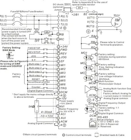
Figure 2 for models of VFD-B Series
VFD022B21A, VFD037B23A/43A/53A, VFD055B23A/43A/53A, VFD075B23A/43A/53A, VFD110B23A/43A/53A
Br ak e r es istor (optional ) Refer to Appendi x B for the use of special brake resi stor
+1 +2/B1 B2
Jumper * For the single phas e driv es, the AC input line can be connected to any two of the three input termi nal s R,S,T * T hree phase input power may apply to single phas e driv es.
-( minus sig n) B R DC chock (optional) AVI ACI AUI ACM 4~20mA -10~+10V +10V 5K 3 2 1 Power supply +10V 20m A Master Fr equency 0 to 10V 47K
Analog S ignal Common
E FWD REV JOG EF MI1 MI2 MI3 MI4 MI6 TRG MI5 DCM +24V Sw1 Sink Source
Fact ory Setting:
SINK Mo de F WD/STOP REV/STO P JO G E.F. Multi-s tep 1 Multi-s tep 2 Multi-s tep 3 Multi-s tep 4 RESET Acc el/Decel prohibit
Counter Digital Si gnal Common F ac tor y
setting
* Don't apply the mains voltage direc tly to abov e terminals. E
Please refer to Fig ure 4 fo r w irin g of S INK mod e and SOURCE mod e.
R(L1) S(L2) T(L3)
F us e/NFB(None Fuse Br eaker)
SA OF F ON MC MC RB RC R(L1) S(L2) T(L3) E
Analog Multi- func tion Output Ter minal
F ac tor y default: A nal og freq. / c ur rent meter 0~1 0VDC/2 mA MO3 U(T1) V(T2) W(T3)
IM
3~
MO1 MO2 AFM ACM RA RB RC MCM RS-485 Motor F ac tor y setting: indicates during operation 48V50mAFac tor y setting: Freq. Setting Indication
Fac tor y setting: Low-voltage Indication Multi-function Photocoulper Output
Analog S ignal common
Seri al interface 1: EV 2: G ND 5:Reserv ed 6: Reserv ed 3: SG- 4: SG + DFM DCM
Digital Frequency Output Ter minal
Fac tor y setting: 1:1 Duty =50% Digital Si gnal Common 48V50mA
48V50mA
E
E
Please refer to Contr ol Ter minal Ex pl anation.
6 1
Main c irc ui t (power) terminals Contr ol c ircuit ter minals Shielded l eads & Cable Recommended Circ ui t when
power s upply is turned O FF by a fault output. T he contact will be O N when the fault occur s to turn off the power and protect the power sys tem.
Chapter 2 Installation and Wiring|VFD-B Series
2-16 Revision July 2008, BE16, SW V4.08 & V5.00
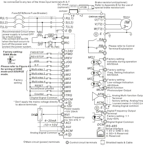
Figure 3 for models of VFD-B Series
VFD150B23A/43A/53A, VFD220B23A/43A/53A, VFD300B23A/43A/53A,
VFD370B23A/43A/53A, VFD450B43A/53A, VFD550B43C/53A, VFD750B43C/53AVFD185B23A/43A/53A,
Br ak e r es istor/unit(optional ) Refer to Appendi x B for the use of special brake resi stor/uni t
+1 +2 Jumper VF DB -( min us sig n) DC chock (optional)
Main c irc ui t (power) terminals Contr ol c ircuit ter minals Shielded l eads & Cable Analog Multi- func tion Output Ter minal
factory setti ng: Analog fr eq. / c ur rent meter 0~1 0VDC/2 mA MO3 U(T1) V(T2) W(T3)
IM
3~
MO1 MO2 AFM ACM RA RB RC MCM RS-485 Motor F ac tor y setting: indicates dur ing operation 48V50mAF ac tor y setting: F req. Setting Indication
F ac tor y setting: Low-voltage Indication Multi-function Photocoulper Output
Analog S ignal common
Seri al interface 1: EV 2: G ND 5:Reserv ed 6: Reserv ed 3: SG- 4: SG + DFM DCM
Digital F requency Output Ter minal
F ac tor y setting: 1:1 Duty =50% Digital Si gnal Common 48V50mA
48V50mA
E
E
Please refer to Contr ol Ter minal Ex pl anation
6 1 AVI ACI AUI ACM 4~20mA -10~+10V +10V 5K 3 2 1 Power supply +10V 20m A Master Fr equency 0 to 10V 47K
Analog S ignal Common
E FWD REV JOG EF MI1 MI2 MI3 MI4 MI6 TRG MI5 DCM +24V Sw1 Sink Source
F act ory set tin g:
SINK Mo de F WD/ST OP REV/STO P JO G E.F. Multi-s tep 1 Multi-s tep 2 Multi-s tep 3 Multi-s tep 4 RESET Acc el/Decel prohibit
Counter Digital Si gnal Common F ac tor y
setting
* Don't apply the mains voltage directly to abov e terminals. E Please refer to F ig u re 4 fo r w irin g of SINK m od e an d SOURCE m od e. R(L1) S(L2) T(L3)
F us e/NF B(None F use Br eaker)
SA OF F ON MC MC RB RC +1 R(L1) S(L2) T(L3) E
* For the single phas e driv es, the AC input line can be connected to any two of the three input termi nal s R,S,T * T hree phase input power may apply to single phas e driv es.
Recommended Circui t when power s upply is turned O FF by a fault output. T he contact will be O N when the fault occur s to turn off the power and protect the power sys tem.
Chapter 2 Installation and Wiring|VFD-B Series
Revision July 2008, BE16, SW V4.08 & V5.00 2-17
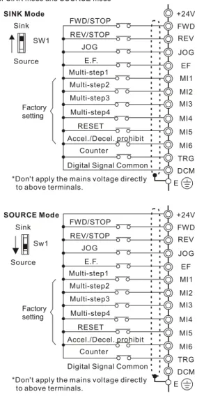
Figure 4 Wiring for SINK mode and SOURCE mode
Factory setting
SINK Mode
*Don't apply the mains voltage directly to above terminals. FWD/STOP REV/STOP Multi-step1 Multi-step2 Multi-step3 Multi-step4
Digital Signal Common
+24V MI1 MI2 MI3 MI4 MI5 MI6 DCM E Sink Source SW1 FWD REV JOG EF TRG JOG E.F. RESET Accel./Decel. prohibit Counter Sw1 Sink Source Factory setting SOURCE Mode
*Don't apply the mains voltage directly to above terminals. FWD/STOP REV/STOP Multi-step1 Multi-step2 Multi-step3 Multi-step4
Digital Signal Common
+24V MI1 MI2 MI3 MI4 MI5 MI6 DCM E FWD REV JOG EF TRG JOG E.F. RESET Accel./Decel. prohibit Counter
Chapter 2 Installation and Wiring|VFD-B Series
2-18 Revision July 2008, BE16, SW V4.08 & V5.00
2.4.2 External Wiring
Motor Output AC Line Reactor Power Supply Magnetic contactor Input AC Line Reactor EMI Filter R/L1 S/L2 T/L3 U/T1 V/T2 W/T3 +2/B1 Zero-phase Reactor Zero-phase Reactor FUSE/NFB B2 -BR BU E BR E +1 DC Chock Items Explanations Power supplyPlease follow the specific power supply requirements shown in Appendix A.
Fuse/NFB (Optional)
There may be an inrush current during power up. Please check the chart of Appendix B and select the correct fuse with rated current. Use of an NFB is optional.
Magnetic contactor (Optional)
Please do not use a Magnetic contactor as the I/O switch of the AC motor drive, as it will reduce the operating life cycle of the AC drive.
Input AC Line Reactor (Optional)
Used to improve the input power factor, to reduce harmonics and provide protection from AC line disturbances (surges, switching spikes, short interruptions, etc.). AC line reactor should be installed when the power supply capacity is 500kVA or more or advanced capacity is activated .The wiring distance should be
≤
10m. Refer to appendix B for details. Zero-phase Reactor (Ferrite Core Common Choke) (Optional)Zero phase reactors are used to reduce radio noise especially when audio equipment is installed near the inverter. Effective for noise reduction on both the input and output sides. Attenuation quality is good for a wide range from AM band to 10MHz. Appendix B specifies the zero phase reactor. (RF220X00A)
EMI filter (Optional)
To reduce electromagnetic
interference, please refer to Appendix B for more details.
Brake Resistor (Optional)
Used to reduce the deceleration time of the motor. Please refer to the chart in Appendix B for specific Brake Resistors.
Output AC Line Reactor (Optional)
Motor surge voltage amplitude depends on motor cable length. For applications with long motor cable (>20m), it is necessary to install a reactor at the inverter output side
Chapter 2 Installation and Wiring|VFD-B Series
Revision July 2008, BE16, SW V4.08 & V5.00 2-19
2.4.3 Main Terminals Connections
Terminal Symbol Explanation of Terminal Function R, S, T R/L1, S/L2, T/L3 AC line input terminals (1-phase/3-phase)
U, V, W U/T1, V/T2, W/T3 AC drive output terminals for connecting 3-phase induction motor
P1, P2 +1, +2 Connections for DC Choke (optional) P-B, P2/B1~B2 +2/B1~B2 Connections for Brake Resistor (optional) P2~N, P2/B1~N +2~(-), +2/B1~(-) Connections for External Brake Unit (VFDB series)
Earth connection, please comply with local regulations.
Mains power terminals (R/L1, S/L2, T/L3)
Connect these terminals (R/L1, S/L2, T/L3) via a no-fuse breaker or earth leakage breaker to 3-phase AC power (some models to 1-phase AC power) for circuit protection. It is
unnecessary to consider phase-sequence.
It is recommended to add a magnetic contactor (MC) in the power input wiring to cut off power quickly and reduce malfunction when activating the protection function of AC motor drives. Both ends of the MC should have an R-C surge absorber.
Do NOT run/stop AC motor drives by turning the power ON/OFF. Run/stop AC motor drives by RUN/STOP command via control terminals or keypad. If you still need to run/stop AC drives by turning power ON/OFF, it is recommended to do so only ONCE per hour. Do NOT connect 3-phase models to a 1-phase power source.
Control circuit terminals (U, V, W)
When the AC drive output terminals U/T1, V/T2, and W/T3 are connected to the motor terminals U/T1, V/T2, and W/T3, respectively, the motor will rotate counterclockwise (as viewed on the shaft end of the motor) when a forward operation command is received. To permanently reverse the direction of motor rotation, switch over any of the two motor leads.
Forward running
Chapter 2 Installation and Wiring|VFD-B Series
2-20 Revision July 2008, BE16, SW V4.08 & V5.00
DO NOT connect phase-compensation capacitors or surge absorbers at the output terminals of AC motor drives.
With long motor cables, high capacitive switching current peaks can cause over-current, high leakage current or lower current readout accuracy. To prevent this, the motor cable should be less than 20m for 3.7kW models and below. And the cable should be less than 50m for 5.5kW models and above. For longer motor cables use an AC output reactor.
Use a well-insulated motor, suitable for inverter operation.
Terminals [+1, +2] for connecting DC reactor
+1
Jumper DC reactor
To improve the power factor and reduce harmonics, connect a DC reactor between terminals [+1, +2]. Please remove the jumper before connecting the DC reactor.
NOTE Models of 15kW and above have a built-in DC reactor.
Terminals [+2/B1, B2] for connecting brake resistor and terminals [+1, +2/B1] for connecting external brake unit
B2
VFDB
-(minus sign)
BR
BR
Connect a brake resistor or brake unit in applications with frequent deceleration ramps, short deceleration time, too low brake torque or requiring increased brake torque.
If the AC motor drive has a built-in brake chopper (all models of 11kW and below), connect the external brake resistor to the terminals [+2/B1, B2].
Models of 15kW and above don’t have a built-in brake chopper. Please connect an external optional brake unit (VFDB-series) and brake resistor. Refer to VFDB series user manual for details.
Connect the terminals [+(P), -(N)] of the brake unit to the AC motor drive terminals [+2(+2/B1), (-)]. The length of wiring should be less than 5m with twisted cable. When not used, please leave the terminals [+2/B1, -] open.
Chapter 2 Installation and Wiring|VFD-B Series
Revision July 2008, BE16, SW V4.08 & V5.00 2-21
WARNING!
1. Short-circuiting [B2] or [-] to [+2/B1] can damage the AC motor drive.
Grounding terminals ( )
Make sure that the leads are connected correctly and the AC drive is properly grounded. (Ground resistance should not exceed 0.1Ω.)
Use ground leads that comply with local regulations and keep them as short as possible. Multiple VFD-B units can be installed in one location. All the units should be grounded
directly to a common ground terminal, as shown in the figure below. Ensure there are no ground loops.
good
excellent not allowed
2.4.4 Control Terminals
Circuit diagram for digital inputs (SINK current 16mA.)
+24 SINK Mode multi-input terminal Internal Circuit DCM +24V Multi-Input Terminal DCM Internal Circuit SOURCE Mode
Terminal symbols and functions Terminal
Symbol Terminal Function
Factory Settings (SINK) ON: Connect to DCM FWD Forward-Stop command ON: Run in FWD direction
OFF: Stop acc. to Stop Method
REV Reverse-Stop command ON: Run in REV direction OFF: Stop acc. to Stop Method
Chapter 2 Installation and Wiring|VFD-B Series
2-22 Revision July 2008, BE16, SW V4.08 & V5.00
Terminal
Symbol Terminal Function
Factory Settings (SINK) ON: Connect to DCM JOG Jog command ON: JOG operation
OFF: Stop acc. to Stop Method
EF External fault
ON: External Fault. Display “EF” and stop acc. To Stop Method.
OFF: No fault
TRG External counter input ON: At every pulse counter is advanced by 1. MI1 Multi-function Input 1
MI2 Multi-function Input 2 MI3 Multi-function Input 3 MI4 Multi-function Input 4 MI5 Multi-function Input 5 MI6 Multi-function Input 6
Refer to Pr.04-04 to Pr.04-09 for programming the Multi-function Inputs.
DFM
Digital Frequency Meter (Open Collector Output)
Max: 48V 50mA DFM-DCM 100% 50% internal circuit
Pulse voltage output monitor signal, proportional to output frequency Duty-cycle: 50% Ratio: Pr.03-07 Min. load: 10KΩ
Max. current: 50mA Max. voltage: 48VDC.
+24V DC Voltage Source +24VDC, 20mA used for SOURCE mode.
DCM Digital Signal Common Common for digital inputs and used for SINK mode.
RA Multi-function Relay output (N.O.) a
RB Multi-function Relay output (N.C.) b
RC Multi-function Relay common
Resistive Load: 5A(N.O.)/3A(N.C.) 240VAC 5A(N.O.)/3A(N.C.) 24VDC Inductive Load: 1.5A(N.O.)/0.5A(N.C.) 240VAC 1.5A(N.O.)/0.5A(N.C.) 24VDC Refer to Pr.03-00 for programming
Chapter 2 Installation and Wiring|VFD-B Series
Revision July 2008, BE16, SW V4.08 & V5.00 2-23
Terminal
Symbol Terminal Function
Factory Settings (SINK) ON: Connect to DCM MO1 Multi-function Output 1 (Photocoupler)
MO2 Multi-function Output 2 (Photocoupler)
MO3 Multi-function Output 3 (Photocoupler)
Maximum 48VDC, 50mA
Refer to Pr.03-01 to Pr.03-03 for programming
MO1~MO3-DCM MO1~MO3 MCM Internal Circuit Max: 48Vdc 50mA
MCM Multi-function output common Common for Multi-function Outputs
+10V Potentiometer power supply +10VDC 20mA
AVI
Analog voltage Input
ACM AVI +10V internal circuit AVI circuit Impedance: 47kΩ Resolution: 10 bits Range: 0 ~ 10VDC = 0 ~ Max. Output Frequency (Pr.01-00) Selection: Pr.02-00, Pr.02-13, Pr.10-00 Set-up: Pr.04-00 ~ Pr.04-03 ACI
Analog current Input
ACM ACI internal circuit ACI circuit Impedance: 250Ω Resolution: 10 bits Range: 4 ~ 20mA = 0 ~ Max. Output Frequency (Pr.01-00) Selection: Pr.02-00, Pr.02-13, Pr.10-00 Set-up: Pr.04-11 ~ Pr.04-14 AUI
Auxiliary analog voltage input
ACM AUI +10 ~ -10V internal circuit AUI circuit Impedance: 47kΩ Resolution: 10 bits Range: -10 ~ +10VDC = 0 ~ Max. Output Frequency (Pr.01-00) Selection: Pr.02-00, Pr.02-13, Pr.10-00 Set-up: Pr.04-15 ~ Pr.04-18
Chapter 2 Installation and Wiring|VFD-B Series
2-24 Revision July 2008, BE16, SW V4.08 & V5.00
Terminal
Symbol Terminal Function
Factory Settings (SINK) ON: Connect to DCM
AFM
Analog output meter AFM ACM 0~10V Max. 2mA potentiometer ACM circuit internal circuit 0 to 10V, 2mA Impedance: 470Ω Output current 2mA max
Resolution: 8 bits
Range: 0 ~ 10VDC
Function: Pr.03-05 ACM Analog control signal
(common) Common for AVI, ACI, AUI, AFM Control signal wiring size: 18 AWG (0.75 mm2) with shielded wire.
Analog input terminals (AVI, ACI, AUI, ACM)
Analog input signals are easily affected by external noise. Use shielded wiring and keep it as short as possible (<20m) with proper grounding. If the noise is inductive, connecting the shield to terminal ACM can bring improvement.
If the analog input signals are affected by noise from the AC motor drive, please connect a capacitor and ferrite core as indicated in the following diagrams:
C
AVI/ACI/AUI ACM
ferrite core
wind each wires 3 times or more around the core Digital inputs (FWD, REV, JOG, EF, TRG, MI1~MI6, DCM)
When using contacts or switches to control the digital inputs, please use high quality components to avoid contact bounce.
Digital outputs (MO1, MO2, MO3, MCM)
Make sure to connect the digital outputs to the right polarity, see wiring diagrams. When connecting a relay to the digital outputs, connect a surge absorber or fly-back diode
Chapter 2 Installation and Wiring|VFD-B Series
Revision July 2008, BE16, SW V4.08 & V5.00 2-25
General
Keep control wiring as far away as possible from the power wiring and in separate conduits to avoid interference. If necessary let them cross only at 90º angle.
The AC motor drive control wiring should be properly installed and not touch any live power wiring or terminals.
NOTE
If a filter is required for reducing EMI (Electro Magnetic Interference), install it as close as possible to AC drive. EMI can also be reduced by lowering the Carrier Frequency. When using a GFCI (Ground Fault Circuit Interrupter), select a current sensor with sensitivity
of 200mA, and not less than 0.1-second detection time to avoid nuisance tripping. For the specific GFCI of the AC motor drive, please select a current sensor with sensitivity of 30mA or above.
DANGER!
Damaged insulation of wiring may cause personal injury or damage to circuits/equipment if it comes in contact with high voltage.
Chapter 2 Installation and Wiring|VFD-B Series
2-26 Revision July 2008, BE16, SW V4.08 & V5.00
2.4.5 Main Circuit Terminals
Frame A, A1, A2: VFD007B21A/23A/43A/53A, VFD015B21A/21B//23A/23B/43A/53A, VFD022B23B/43B/53A L1 / S/ T/ +2/B1 U/T1 V/T2W/T3 R L2 L3
+1
B2
Control Terminal Torque: 4Kgf-cm (3 in-lbf) Wire: 12-24 AWG (3.3-0.2 mm2) Power Terminal Torque: 18 kgf-cm (15.6 in-lbf)Wire Gauge: 10-18 AWG (5.3-0.8 mm2) stranded wire, 12-18 AWG (3.3-0.8 mm2) solid wire Wire Type: Copper only, 75°C
Chapter 2 Installation and Wiring|VFD-B Series
Revision July 2008, BE16, SW V4.08 & V5.00 2-27
Frame B: VFD022B21A, VFD037B23A/43A/53A
+1
+2 B1-
B
2 R/L1 S/L2 T/L3 Screw Torque : Wire Gauge : 18Kgf-cm 18~10AWG U/T1 V/T2 W/T3 Control Terminal Torque: 4Kgf-cm (3 in-lbf) Wire: 12-24 AWG (3.3-0.2mm2) Power Terminal Torque: 18 kgf-cm (15.6 in-lbf) Wire Gauge: 10-18 AWG (5.3-0.8mm2) Wire Type: Stranded copper only, 75°CChapter 2 Installation and Wiring|VFD-B Series
2-28 Revision July 2008, BE16, SW V4.08 & V5.00
Frame C: VFD055B23A/43A/53A, VFD075B23A/43A/53A, VFD110B23A/43A/53A
POWER 3IMMOTOR Control Terminal Torque: 4Kgf-cm (3 in-lbf) Wire: 12-24 AWG (3.3-0.2mm2) Power Terminal Torque: 30Kgf-cm (26 in-lbf) Wire: 8-12 AWG (8.4-3.3mm2) Wire Type: Stranded Copper only, 75°C
Chapter 2 Installation and Wiring|VFD-B Series
Revision July 2008, BE16, SW V4.08 & V5.00 2-29
Frame D: VFD150B23A/43A/53A, VFD185B23A/43A/53A, VFD220B23A/43A/53A
3IM POWER S/L2 R/L1 - ( ) ( ) + DC DC T/L3 +1 +2
-MOTOR W/T3 V/T2 Control Terminal Torque: 4Kgf-cm (3 in-lbf) Wire: 12-24 AWG (3.3-0.2 mm2) Power Terminal Torque: 30Kgf-cm (26 in-lbf) Wire: 2-8 AWG (33.6-8.4 mm2) Wire Type: Stranded Copper only, 75°CChapter 2 Installation and Wiring|VFD-B Series
2-30 Revision July 2008, BE16, SW V4.08 & V5.00
Frame E1: VFD300B23A, VFD370B23A, VFD550B43C, VFD750B43C, VFD550B53A, VFD750B53A POWER ALARM W/T3 S/L2 R/L1 T/L3 +1 +2 U/T1 V/T2 (173in-lbf) Screw Torque: 200kgf-cm POWER IM3MOTOR CHARGE Control Terminal Torque: 4Kgf-cm (3 in-lbf) Wire: 12-24 AWG (3.3-0.2 mm2) Power Terminal Torque: 200kgf-cm (173 in-lbf) Wire Gauge: 1 - 3/0 AWG (42.4-85 mm2) Wire Type: Stranded copper only, 75°C
Chapter 2 Installation and Wiring|VFD-B Series
Revision July 2008, BE16, SW V4.08 & V5.00 2-31
Frame E: VFD300B43A, VFD370B43A, VFD450B43A, VFD300B53A, VFD370B53A, VFD450B53A R/L1S/L2 T/L3 +1+2 - U/T1 V/T2 2/T3 POWER IM MOTOR 3 CHARGE POWER ALARM Control Terminal Torque: 4Kgf-cm (3 in-lbf) Wire: 12-24 AWG (3.3-0.2 mm2) Power Terminal
Torque: 58.7kgf-cm (50.9 in-lbf) max. Wire Gauge: 2-6AWG (33.6-13.3 mm2) Wire Type: Stranded copper only, 75°C
Chapter 2 Installation and Wiring|VFD-B Series
Revision July 2008, BE16, SW V4.08 & V5.00 3-1
Chapter 3 Start Up
3.1 Preparations before Start-up
Carefully check the following items before proceeding.
Make sure that the wiring is correct. In particular, check that the output terminals U, V, W. are NOT connected to power and that the drive is well grounded.
Verify that there are no short-circuits between terminals and from terminals to ground or mains power.
Check for loose terminals, connectors or screws.
Verify that no other equipment is connected to the AC motor
Make sure that all switches are OFF before applying power to ensure that the AC motor drive doesn’t start running and there is no abnormal operation after applying power. Make sure that the front cover is correctly installed before applying power. Do NOT operate the AC motor drive with humid hands.
Check the following items after applying power:
- The keypad should light up as follows (normal status with no error)
U F H STOP RUN REV VFD-PU01 FWD JOG JOG
RUN
RESETSTOPWhen power is ON, LEDs "F", "STOP" and "FWD" should light up. The display will show "60.00" with the least signification "0" flashing.
- If the drive has built-in fan (2.2kW and above) it should run. The factory setting of Fan Control Pr.03-12=00 (Fan always on).
Chapter 3 Start Up|VFD-B Series
3-2 Revision July 2008, BE16, SW V4.08 & V5.00
3.2 Operation Method
Refer to 4.2 How to operate the digital keypad VFD-PU01 and chapter 5 parameters for setting. Please choose a suitable method depending on application and operation rule. The operation is usually used as shown in the following table.
3.3 Trial Run
After finishing checking the items in “3.1 preparation before start-up”, you can perform a trial run. The factory setting of the operation source is from the keypad (Pr.02-01=00).
1. After applying power, verify that LED “F” is on and the display shows 60.00Hz. 2. Setting frequency to about 5Hz by using key.
3. Pressing
RUN
key for forward running. And if you want to change to reverse running, you should press key in UF H
page. And if you want to decelerate to stop, please press RESETSTOP key.
4. Check following items:
Check if the motor direction of rotation is correct.
Check if the motor runs steadily without abnormal noise and vibration. Check if acceleration and deceleration are smooth.
If the results of trial run are normal, please start the formal run.
Operation Method Frequency Source Command SourceOperation
PU01 keypad
RUN
RESETSTOP
MI1
MI2
DCM
Parameter setting: 04-04=11 04-05=12 Operate from external signalAVI, ACI, AUI
External terminals input: FWD-DCM REV-DCM
Chapter 3 Start Up|VFD-B Series
Revision July 2008, BE16, SW V4.08 & V5.00 3-3
NOTE
1. Stop running immediately if any fault occurs and refer to the troubleshooting guide for solving the problem.
2. Do NOT touch output terminals U, V, W when power is still applied to L1/R, L2/S, L3/T even when the AC motor drive has stopped. The DC-link capacitors may still be charged to hazardous voltage levels, even if the power has been turned off.
3. To avoid damage to components, do not touch them or the circuit boards with metal objects or your bare hands.
Chapter 3 Start Up|VFD-B Series
3-4 Revision July 2008, BE16, SW V4.08 & V5.00
Revision July 2008, BE16, SW V4.08 & V5.00 4-1
Chapter 4 Digital Keypad Operation
4.1 Description of the Digital Keypad VFD-PU01
U F H
VFD-PU01
JOG
RUN
RESETSTOPLED Display
Display frequency, current, voltage and error, etc.
Status Display Display of drive status Part Number
RUN key STOP/RESET MODE
Display mode selector Left key
Moves cursor to the left
UP and DOWN Key Sets the parameter number and changes the numerical data, such as Master Frequency. JOG Jog operation selector
Display Message Descriptions
Displays the AC drive Master Frequency.
Displays the actual output frequency present at terminals U/T1, V/T2, and W/T3.
User defined unit (where U = F x Pr.00-05)
Displays the output current present at terminals U/T1, V/T2, and W/T3.
Chapter 4 Digital Keypad Operation|VFD-B Series
4-2 Revision July 2008, BE16, SW V4.08 & V5.00
Display Message Descriptions
Displays the AC motor drive reverse run status.
The counter value (C).
Displays the selected parameter.
Displays the actual stored value of the selected parameter.
External Fault.
Display “End” for approximately 1 second if input has been accepted by pressing key. After a parameter value has been set, the new value is automatically stored in memory. To modify an entry, use the
, and keys.
Chapter 4 Digital Keypad Operation|VFD-B Series
Revision July 2008, BE16, SW V4.08 & V5.00 4-3
4.2 How to Operate the Digital Keypad VFD-PU01
MODE MODE MODE MODE MODE MODE START U F H Selection mode START To shift cursor To modify data To set direction or To set parameters U F H U F H U F H GO START U F H U F H U F H U F H U F H U F H
to set the parameters. NOTE : In the selection mode, press
to return to the selection mode. NOTE : In the parameter setting mode, you can press
move to previous display
U F H U F H U F H U F H U F H START U F H U F H U F H U F H or U F H U F H
parameter set successfully
parameter set error MODE
Chapter 4 Digital Keypad Operation|VFD-B Series
4-4 Revision July 2008, BE16, SW V4.08 & V5.00
Revision July 2008, BE16, SW V4.08 & V5.00 5-1
Chapter 5 Parameters
The VFD-B parameters are divided into 12 groups by property for easy setting. In mostapplications, the user can finish all parameter settings before start-up without the need for re-adjustment during operation.
The 12 groups are as follows:
Group 0: User Parameters Group 1: Basic Parameters
Group 2: Operation Method Parameters Group 3: Output Function Parameters Group 4: Input Function Parameters
Group 5: Multi-Step Speed and PLC Parameters Group 6: Protection Parameters
Group 7: Motor Parameters Group 8: Special Parameters Group 9: Communication Parameters Group 10: PID Control Parameters Group 11: Fan & Pump Control Parameters
Chapter 5 Parameters|VFD-B Series
5-2 Revision July 2008, BE16, SW V4.08 & V5.00
5.1 Summary of Parameter Settings
: The parameter can be set during operation. Group 0 User Parameters
Parameter Explanation Settings Factory SettingCustomer
00-00 Identity Code of
the AC motor drive Read-only ##
00-01 Rated Current Display of the AC motor drive
Read-only #.#
08: Keypad lock
09: All parameters are reset to factory settings (50Hz, 220V/380V/575V)
00-02 Parameter Reset
10: All parameters are reset to factory settings (60Hz, 220V/440V/575V)
00
00: Display the frequency command value (LED F)
01: Display the actual output frequency (LED H) 02: Display the content of user-defined unit
(LED U)
03: Multifunction display, see Pr.00-04 00-03 Start-up Display
Selection
04: FWD/REV command
00
00: Display output current (A) 01: Display counter value (C) 02: Display process operation (1.tt) 03: Display DC-BUS voltage (u) 04: Display output voltage (E) 05: Output power factor angle (n) 06: Display output power (P) 07: Display actual motor speed (HU) 08: Display the estimated value of torque as it
relates to current (t)
09: Display PG numbers/10ms (G)
10: Display analog feedback signal value (b)(%) 11: Display AVI (U1.) (%)
12: Display ACI (U2.) (%) 13: Display AUI (U3.) (%) 00-04 Content of Multi Function Display
14: Display the temperature of heat sink (°C) 00
00-05 User-Defined Coefficient K 0.01 to 160.00 1.00
00-06 Software Version Read-only #.##
00-07 Password Input 00 to 65535 00 00-08 Password Set 00 to 65535 00 00: V/f Control 01: V/f + PG Control 02: Vector Control 00-09 Control Method 03: Vector + PG Control 00
Chapter 5 Parameters|VFD-B Series
Revision July 2008, BE16, SW V4.08 & V5.00 5-3
Parameter Explanation Settings Factory SettingCustomer
00-10 Reserved
Group 1 Basic Parameters
Parameter Explanation Settings Factory SettingCustomer
01-00 Maximum Output Frequency (Fmax) 50.00 to 400.00 Hz 60.00 01-01 Maximum Voltage Frequency (Fbase) 0.10 to 400.00 Hz 60.00 230V series: 0.1V to 255.0V 220.0 460V series: 0.1V to 510.0V 440.0 01-02 Maximum Output
Voltage (Vmax)
575V series: 0.1V to 637.0V 575.0 01-03 Mid-Point Frequency (Fmid) 0.10 to 400.00 Hz 0.50 230V series: 0.1V to 255.0V 1.7 460V series: 0.1V to 510.0V 3.4 01-04 Mid-Point Voltage (Vmid)
575V series: 0.1V to 637.0V 4.8 01-05 Minimum Output Frequency (Fmin) 0.10 to 400.00 Hz 0.50 230V series: 0.1V to 255.0V 1.7 460V series: 0.1V to 510.0V 3.4 01-06 Minimum Output Voltage (Vmin)
575V series: 0.1V to 637.0V 4.8 01-07 Output Frequency Upper Limit 1 to 120% 100 01-08 Output Frequency Lower Limit 0 to100 % 0
01-09 Accel Time 1 0.01 to 3600.0 sec 10.0 01-10 Decel Time 1 0.01 to 3600.0 sec 10.0 01-11 Accel Time 2 0.01 to 3600.0 sec 10.0 01-12 Decel Time 2 0.01 to 3600.0 sec 10.0 01-09 ~ 01-12: Factory setting for models of 30hp (22kW) and above is 60sec. 01-13 Jog Acceleration
Time 0.1 to 3600.0 sec 1.0
01-14 Jog Frequency 0.10 Hz to 400.00 Hz 6.00 00: Linear Accel/Decel
01: Auto Accel, Linear Decel 02: Linear Accel, Auto Decel 03: Auto Accel/Decel (Set by load) 01-15
Auto acceleration / deceleration (refer to Accel/Decel time
setting) 04: Auto Accel/Decel (set by Accel/Decel Time setting)
00
01-16 Acceleration S-Curve 00 to 07 00
01-17 Deceleration S-Curve 00 to 07 00
01-18 Accel Time 3 0.01 to 3600.0 sec 10.0 01-19 Decel Time 3 0.01 to 3600.0 sec 10.0 01-20 Accel Time 4 0.01 to 3600.0 sec 10.0
Chapter 5 Parameters|VFD-B Series
5-4 Revision July 2008, BE16, SW V4.08 & V5.00
Parameter Explanation Settings Factory SettingCustomer
01-21 Decel Time 4 0.01 to 3600.0 sec 10.0 01-18 ~ 01-21: Factory setting for models of 30hp (22kW) and above is 60sec. 01-22 Jog Deceleration
Time 0.1 to 3600.0 sec 1.0
00: Unit: 1 sec 01: Unit: 0.1 sec 01-23 Accel/Decel Time Unit
02: Unit: 0.01 sec
01
Group 2 Operation Method Parameters
Parameter Explanation Settings Factory SettingCustomer
00: Digital keypad (PU01) UP/DOWN keys or Multi-function Inputs UP/DOWN. Last used frequency saved.
01: 0 to +10V from AVI 02: 4 to 20mA from ACI 03: -10 to +10Vdc from AUI
04: RS-485 serial communication (RJ-11). Last used frequency saved. 05: RS-485 serial communication (RJ-11).
Last used frequency not saved. 02-00 Source of First Master Frequency
Command
06: Combined use of master and auxiliary frequency command
(See Pr. 02-10 to 02-12)
00
00: Digital keypad (PU01)
01: External terminals. Keypad STOP/RESET enabled.
02: External terminals. Keypad STOP/RESET disabled.
03: RS-485 serial communication (RJ-11). Keypad STOP/RESET enabled. 02-01 Source of First Operation Command
04: RS-485 serial communication (RJ-11). Keypad STOP/RESET disabled.
00
00: STOP: ramp to stop; E.F.: coast to stop 01: STOP: coast to stop; E.F.: coast to stop 02: STOP: ramp to stop; E.F.: ramp to stop 02-02 Stop Method
03: STOP: coast to stop; E.F.: ramp to stop 00 230V&460V:1-5hp/0.75-3.7kW: 1-15kHz 15 7.5-25hp/5.5-18.5kW: 01-15kHz 09 30-60hp/22-45kW: 01-09kHz 06 75-100hp/55-75kW: 01-06kHz 06 575V: 1-15hp/0.75-11kW: 01-10 kHz 06 20-60hp/15-45kW: 01-08 kHz 06 02-03 PWM Carrier Frequency Selections 75-100hp/55-75kW: 01-06kHz 06
Chapter 5 Parameters|VFD-B Series
Revision July 2008, BE16, SW V4.08 & V5.00 5-5
Parameter Explanation Settings Factory SettingCustomer
00: Enable forward/reverse operation 01: Disable reverse operation 02-04 Motor Direction
Control
02: Disabled forward operation
00 00: 2-wire: FWD/STOP, REV/STOP
01: 2-wire: FWD/REV, RUN/STOP 02-05 2-wire/3-wire Operation Control
Modes 02: 3-wire operation
00 00: Disable. Operation status is not changed
even if operation command source Pr.02-01 and/or Pr.02-14 is changed. 01: Enable. Operation status is not changed
even if operation command source Pr.02-01 and/or Pr.02-14 is changed. 02: Disable. Operation status will change if
operation command source Pr.02-01 and/or Pr.02-14 is changed. 02-06 Line Start Lockout
03: Enable. Operation status will change if operation command source Pr.02-01 and/or Pr.02-14 is changed.
00
00: Decelerate to 0 Hz
01: Coast to stop and display “EF” 02-07 Loss of ACI Signal (4-20mA)
02: Continue operation by last frequency command
00
00: Based on accel/decel time 01: Constant speed 02-08 Up/Down Mode
02: Based on accel/decel time, but frequency command will be 0 when stopped.
00 02-09 Accel/Decel Rate of Change of UP/DOWN Operation with Constant Speed 0.01~1.00 Hz/msec 0.01
00: Digital keypad (PU01) UP/DOWN keys or Multi-function Inputs UP/DOWN. Last used frequency saved.
01: 0 to +10V from AVI 02: 4 to 20mA from ACI 03: -10 to +10Vdc from AUI 02-10 Source of the Master Frequency
Command
04: RS-485 serial communication (RJ-11). Last used frequency saved.
00
00: Digital keypad (PU01) UP/DOWN keys or Multi-function Inputs UP/DOWN. Last used frequency saved.
01: 0 to +10V from AVI 02: 4 to 20mA from ACI 03: -10 to +10Vdc from AUI 02-11 Source of the Auxiliary Frequency
Command
04: RS-485 serial communication (RJ-11). Last used frequency saved.
00
00: Master frequency + auxiliary frequency 02-12
Combination of the Master and Auxiliary Frequency
Command 01: Master frequency - auxiliary frequency 00
Chapter 5 Parameters|VFD-B Series
5-6 Revision July 2008, BE16, SW V4.08 & V5.00
Parameter Explanation Settings Factory SettingCustomer
00: Digital keypad (PU01) UP/DOWN keys or Multi-function Inputs UP/DOWN. Last used frequency saved.
01: 0 to +10V from AVI 02: 4 to 20mA from ACI 03: -10 to +10Vdc from AUI
04: RS-485 serial communication (RJ-11). Last used frequency saved
05: RS-485 serial communication (RJ-11). Last used frequency not saved. 02-13 Source of Second Frequency
Command
06: Combined use of master and auxiliary frequency command (See Pr. 10 to 02-12)
00
00: Digital keypad (PU01)
01: External terminals. Keypad STOP/RESET enabled.
02: External terminals. Keypad STOP/RESET disabled.
03: RS-485 serial communication (RJ-11). Keypad STOP/RESET enabled. 02-14 Source of Second Operation Command
04: RS-485 serial communication (RJ-11). Keypad STOP/RESET disabled.
00
02-15 Keypad Frequency Command 0.00 ~ 400.00Hz 60.00
Group 3 Output Function Parameters
Parameter Explanation Settings Factory SettingCustomer
00: No function 01: AC drive operational 02: Master frequency attained 03-00 Multi-Function Output Relay (RA1,
RB1, RC1)
03: Zero speed
08
04: Over torque detection 05: Base-Block (B.B.) indication 06: Low-voltage indication 03-01 Multi-Function Output Terminal
MO1
07: Operation mode indication
01
08: Fault indication
09: Desired frequency attained 1 10: PLC program running 03-02 Multi-Function Output Terminal
MO2
11: PLC program step completed
02
12: PLC program completed 13: PLC program operation paused 14: Terminal count value attained 15: Preliminary count value attained 16: Auxiliary motor No.1
03-03 Multi-Function Output Terminal MO3
17: Auxiliary motor No.2
Chapter 5 Parameters|VFD-B Series
Revision July 2008, BE16, SW V4.08 & V5.00 5-7
Parameter Explanation Settings Factory SettingCustomer
18: Auxiliary motor No.3 19: Heat sink overheat warning 20: AC motor drive ready 21: Emergency stopindication 22: Desired frequency attained 2 23: Software brake signal 24: Zero speed output signal 25: Under-current detection 26: Operation indication (H>=Fmin) 27: Feedback signal error
28: User-defined low-voltage detection 29: Brake control (Desired frequency attained
3) 03-04 Desired Frequency
Attained 1 0.00 to 400.00 Hz 0.00
00: Analog frequency meter 01: Analog current meter 02: Output voltage
03: Output frequency command 04: Output motor speed 03-05 Analog Output Signal
05: Load power factor (cos90o to Cos0o)
00
03-06 Analog Output Gain 01 to 200% 100
03-07 Digital Output Multiplying Factor 01 to 20 01 03-08 Terminal Count Value 00 to 65500 00 03-09 Preliminary Count Value 00 to 65500 00
03-10 Desired Frequency Attained 2 0.00 to 400.00 Hz 0.00 00: Preliminary count value attained, no EF
display 03-11 EF Active When Preliminary Count
Value Attained 01: Preliminary count value attained, EF active
00
00: Fan always ON
01: 1 minute after AC motor drive stops, fan will be OFF
02: AC motor drive runs and fan ON, AC motor drive stops and fan OFF 03-12 Fan Control
03: Fan ON to run when preliminary heatsink temperature attained
00
03-13 Brake Release Frequency 0.00 to 400.00Hz 0.00 03-14 Brake Engage Frequency 0.00 to 400.00Hz 0.00
Chapter 5 Parameters|VFD-B Series
5-8 Revision July 2008, BE16, SW V4.08 & V5.00
Group 4 Input Function Parameters
Parameter Explanation Settings Factory SettingCustomer
04-00 AVI Analog Input Bias 0.00~200.00 % 0.00 00: Positive bias
04-01 AVI Bias Polarity 01: Negative bias 00
04-02 AVI Input Gain 1 to 200 % 100
00: No AVI negative bias command 01: Negative bias: REV motion enabled 04-03 AVI Negative Bias, Reverse Motion
Enable/Disable 02: Negative bias: REV motion disabled
00
00: No function 01
01: Multi-Step speed command 1 04-04 Multi-Function Input
Terminal 1 (MI1)
02: Multi-Step speed command 2 03: Multi-Step speed command 3
04: Multi-Step speed command 4 02 05: External reset (N.O.)
06: Accel/Decel inhibit
07: Accel/Decel time selection command 1 04-05 Multi-Function Input
Terminal 2 (MI2)
08: Accel/Decel time selection command 2 09: External base block (N.O.) 03 10: External base block (N.C.)
04-06 Multi-Function Input Terminal 3 (MI3)
11: Up: Increment master frequency
12: Down: Decrement master frequency 04 13: Counter reset
14: Run PLC program 04-07 Multi-Function Input
Terminal 4 (MI4)
15: Pause PLC program
16: Auxiliary motor No.1 output disable 05 17: Auxiliary motor No.2 output disable
18: Auxiliary motor No.3 output disable 04-08 Multi-Function Input
Terminal 5 (MI5)
19: Emergency stop (N.O.)
20: Emergency stop (N.C.) 06 21: Master frequency selection AVI/ACI
22: Master frequency selection AVI/AUI 23: Operation command selection
(keypad/external terminals) 24: Auto accel/decel mode disable 25: Forced stop (N.C.)
26: Forced stop (N.O.) 27: Parameter lock enable (N.O.) 28: PID function disabled 29: Jog FWD/REV command 04-09 Multi-Function Input
Terminal 6 (MI6)