Embedded Home Security System
Design, implementations, and overview
Shawn Johnson
Computer Science, College of Natural Sciences Colorado State University
Fort Collins, United States
Eric Fry
Computer Science, College of Natural Sciences Colorado State University
Fort Collins, United States [email protected]
Abstract—An exploration of feasible and practical options to instantiate an integrated home security system with viable communication options.
Keywords-component; home-security, arduino, motion sensor, remote monitoring.
I. MOTIVATIONS AND LIMITATIONS
Unfortunately during tough economic times the burglary rates tend to increase. While one would like to believe that our homes are sanctuaries and that nothing bad could happen to us; that’s simply not how the world works. We wanted to provide an affordable system to deter a would-be intruder. In order to achieve this there are a few steps. First the perpetrator must be aware that there is a system in place, second there must be some alert to inform the home owner to allow them to make a decision about the situation. Finally there must be a recording device to track what has happened, this can later be used to aid police efforts to locate the valuables you undoubtedly wish to recover. While it may seem like there are already a slew of options in the field of security systems we realized how often these systems were absurdly expensive either having extreme hook-up fees or forcing the owner into a monthly contract which becomes very expensive with time. We want to implement a system that is both inexpensive and a onetime cost and feel there is a real market for a solution such as ours. One final motivation was that Eric’s mother had mentioned it would be something she would be interested in. A limitation of this system that some may consider paranoid is our decision to have all the components directly related to security to be strictly wired. The reasoning for this is that there are options out there to scramble a large array of channels and using wireless for cameras for instance could be disrupted if someone were running a Linux flashed wireless N router broadcasting freely.
II. EASE OF USE
One of the major pitfalls of home security systems is that they are only valuable if used regularly and used properly. We wanted to keep this relatively simple idea in our mind throughout the design of this project to ensure that it will be truly useful. We had hoped we would have scheduling completed where one could input the hours they expected to be out of the house and the alarm would engage and disengage itself automatically. While this functionality did not make it
into our prototype it is still something that we wish to implement on our own at some point in the future. We also would have liked to have had user control over which sensors the system monitored. A keypad would have been beneficial in all removing the computer requirement, but our concern was that people have difficulties setting their thermostat and our system obviously would have more functions. We designed a GUI on the computer to allow the user easy access to system details. This also benefited the system by allowing remote access using Remote Desktop Connection for example.
III. PROTOTYPE
We wanted to have a working model that we could show, it needed to be portable, and needed to operate in the same overall fashion as the final product we hope to have at some point.
The components we used in our prototype are as follows:
A. Arduino Mega
The Arduino Mega is the driver behind our entire project, not only does it receive and interpret signals from our sensor devices, but it also allowed us to run the program entirely on it (lacking the benefits of the GUI and inexpensive cameras of course). Our reasoning for picking the Mega was that we knew for our prototype it would supply ample configurability and we would not have to be concerned with running out of connectors. This microcontroller uses 3.3V and 5V to power its related devices and is itself powered either by USB 500mA or can be powered via an external source up to 12V. We decided to power using USB partially due to convenience and also the added benefit of limiting harm done to the system by any mistakes we could potentially make in connections. The Mega is affordable at roughly sixty dollars.
B. Computer
Used to create a more user friendly connection to our system.
Allowed our project to stay very inexpensive by using the computer to control cameras.
Provided an interface which we could use to present the different sensors reporting for our demonstration.
Gave a very polished look to our system using Swing to generate not only a GUI but also a taskbar icon.
Send our e-mail alerts without needing to get a LAN attachment for our Arduino.
C. Parallax PIR
This sensor is your typical passive infrared device. It detects motion at a distance of about 20 feet. This unit is relatively simple and has two output modes to choose from. We chose to use the high signal when motion was present. These have a retail cost of about ten dollars. We decided to use two to show the sensors picking up different sides of the room.
Parallax PIR
D. Normally Closed Magnetic Switch
This very simple object is a key component in almost every home security system found. Essentially while the door or window that you are monitoring is closed the current will flow through the switch. If however one opens the window or door the current will stop and we can act appropriately. The range on prices is quite large anywhere from two dollars to ten dollars with shipping and order quantity tending to be the limitations.
Normally Closed Magnetic Switch
E. SkyLink Universal garage door remote control
This was an attempt to create a simple control scheme for the basic arm and disarm capabilities. These are easily configurable as buttons which we had planned to use 1 receiver to arm, one to disarm and finally one that would act as a panic switch. Each receiver is able to communicate with many
devices and each keypad can be used with up to 10 receivers. In the presented prototype we had last minute issues with the power building up and creating false positives when set with the Arduino, essentially lacking the proper resistor to allow the charge to drop to ground if it was not enabled. We did however get these items working with an LED to showcase their basic function and that they interacted appropriately. The advantage this system offered was that the wireless keypads or remote keys could be used anywhere in the house or have one in the bedroom, one in the garage and one at the front door. Initially we had thought of using the panic receiver as a way of switching the system state but concerns of setting the alarm when intending to disarm and vice-versa arose. We were able to get these at about fifteen dollars each and had 3 of them to accommodate the functions we desired.
Skylink receiver and keypad
F. Buzzer
We used a basic 3V buzzer to be used to give an audible response to the user without requiring them to use the GUI on the computer. Predominantly for allowing the user to know when the alarm is being armed or disarmed and giving an audible alert with a timer before setting the alarm to give the user time to lock the facility if they are leaving. This item can be found at your local electronics store for under five dollars
G. Cameras
For our prototype we opted to go with webcams while these do not support the final goals of our project they do make it extremely viable as a cheap alternative. To get a real camera system that was able to record the way we wanted would have been at a minimum of one-hundred dollars. We used a thirteen dollar webcam and a webcam that was borrowed in order to implement two control styles. In total we spent thirteen dollars on our webcam.
Our prototype had the following functionality:
It was able to detect using all 4 sensors, which could be monitored via our GUI on the computer.
Using java and system calls we enabled the system to send e-mail alerts if an intrusion was detected, which can be forwarded to cellular telephones.
The alarm could be enabled or disabled from either the toolbar icon or from the application window.
Webcam implementations; one was an always on motion detector taking still images. The other was set up using a command prompt implementation that would allow up to twenty minutes of video and audio to be recorded.
IV. DIFFICULTIES
Being computer science majors an obvious difficulty was the lack of working knowledge of circuits and the practice of balancing proper voltage. This became apparent more than once throughout this project when we learned about how to use pull up and pull down resistors. Another obstacle was the script that we ran contacted an SMTP mail server directly which was not permitted by the firewall at our university where the demonstration was given, we overcame this by using remote desktop connection to demonstrate the ability of our batch files of running the webcams or sending e-mails. Setting up the serial connection from our java program to the proper COM port to be able to send and receive messages was definitely a learning experience and required us to add a library to our java folder (rxtx). The motion detectors seemed to be a constant struggle for us and regrettably something we put way too much time into. At first we felt that they worked, or at least appeared to work however; we realized that it was simply our perception that they were picking up ambient temperature changes since the window was open. These sensors require a calibration period of about sixty seconds which can become quite a nuisance when you are constantly resetting them and trying a new configuration to hope that a resistor you just placed will fix your problems. Eventually we got them working on an LED but when we set them back to the Arduino we would once again receive a period signal after the first trigger. After asking the class and looking over the breadboard repeatedly we discovered that our use of the transistor for our buzzer was incorrect and when the was to go off it was sending the voltage intended for the buzzer to ground, which I believe was able to draw enough mA to turn off the motion detector, which stopped the grounding which in turn started the cycle again. So we fixed this and adapted some code that was
supplied with the motion detector to help us set the sensitivity of the motion detectors. After that fiasco we assumed we were relatively in the clear and all else would go as planned; all devices had previously been tested and shown to work. But as any project manager knows there will always be delays even on the most basic of tasks. Next while implementing the garage door keypads we discovered that they were not properly getting grounded if the connection was supposed to be incomplete and so charge would build up and eventually have enough to circumvent the button and complete the circuit enabling disabling or panicking the system periodically. We had encountered an issue like this before when first learning how to program on the Arduino and practicing with a simple button. To solve this issue we added a resistor from the powered side of the button to ground. Unfortunately this didn’t work for some reason when we were finishing up the project. We attempted to change the resistance between the buttons and ground but either ended up sending the signal to ground always or encountering the same period issue. These issues definitely set us back on time and prevented us from being able to present as much as we had wanted.
V. GRAPHICAL USER INTERFACE
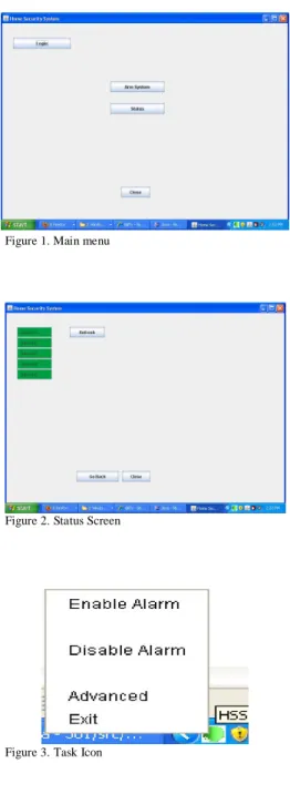
The GUI we designed was to allow us to showcase our current system and also support future implementations and enhancements. We kept with standard practices making sure to keep common buttons in the same places among different screens shown in Figures 1 and 2 of the following page, and we also made sure that the user had ample notifications if they had been attempting to exit the program to minimize the likelihood of accidentally closing the program shown in Figure 3 again on the following page. We knew that users would not like to have their alarm as an open program with its own window all the time so we tried something we hadn’t done before which was to implement a task tray icon which the user could leave running in the background unhindered which is shown in Figure 4 on the following page. Some things we could improve of the overall appearance would be to use the toolkit
to find the resolution of the monitor that the application was being displayed on and set the startup position based on that information. Another cosmetic idea is that we are able to use any picture file that we would like to be our task icon and that we could potentially create a logo and use it there.
Figure 1.Main menu
Figure 2. Status Screen
Figure 3. Task Icon
VI. CODING
Writing the code for this project was an interesting experience and something that we could have improved upon especially given our experience as Computer Science majors. First we will talk about our Java programming that was done for this project. We picked Java for its cross-platform capabilities and also because it was a familiar language with tools that we could use to debug issues that arose.
A. Java Coding
After taking 3 years of computer science courses I was surprised to find how much the coding practices that we have been taught so fundamentally were ignored as we tried to scrape the pieces together to accomplish this task in time. The fundamentally difficult thing here was the amount of code that we had to forge together. The main application had been adapted from a program we wrote in another class and the serial communication was adapted from the rxtx example. The serial code was built as a hello world style program and we needed to change that to interface with not only the main program but the task icon as well. Initially this caused lots of grief as we learned how to proper initialize the class to start the connection and not call the class again while still returning the class. Luckily once we had the connection it was
relatively easy to send data back and forth and to use a switch statement to allow our java program to handle all of the different type of situations we had expected. We did however have to modify the send code for the rxtx and allow it to send the message we wanted as opposed to a hello world that had been hard coded in. If the code were to be expanded into the future we would probably need to implement messages that are longer than one byte. But for the scope of our
demonstration 256 types of messages each way was more than enough. To implement these messages you would simply need to either create a size then message convention or hardcode a larger size in so each send and receive will know the size to expect and the program will not pass on the data until the proper size has been achieved. The task icon was something that neither of us had done before but we felt was a worthwhile endeavour and would benefit the overall feel of our product. Getting the main program to hide as opposed to ending the program was something that took some
investigation as well.
On the Arduino side of things this was our first time programming on a microcontroller and it was difficult to learn what an appropriate practice was. Our program on the Arduino is lacking elegance and design. Our iterative approach to this project was good to master each set of required skills however our lack of understanding the in beginning lead to almost no concept of design before implementing the code. Portions of our code are in methods that are called inside of the main loop while there are still sizeable code fragments in the main loop that had not been put into their own methods. Questions arose such as will the compiler search through the entire code like java and then jump to the main and run from their or will it work more like C where you must at least declare the names of all the functions that you will use before the compiler reaches main. When we set an output to low does this ground the cable that is attached to it, which we discovered later that it does. Serial connections on the Arduino Mega were a dream very easy to use to send and receive data and there were plenty of examples to be found in library again an easy switch statement and we were well on our way. The only issue with this is the way the code looks the receive function was still done in the main loop and made the code much more disorganized than it probably should have been at our level of programming.
VII. FUTURE WORK
There were many things in this project that we had hoped to have completed before the time came to present our prototype we will be taking a look at these items and why they were not implemented and what it will take to implement them in the future.
A. Schedule based automatic activation
Our vision for this is that you would input your schedule and the system will arm and disarm itself appropriately, one of the difficulties in doing this was we did not want to create false alarms in the case that someone left the windows open while they went to work one day or the back door was open for the dog and never got closed before arming the alarm. Our solution to this was to have the Arduino recognize that it was being armed in scheduled mode and to treat sensors that were already triggered as non alarm critical events. The other thing this system could do would be to e-mail you and let you know which sensors it was ignoring during that time period. This idea had a few complications to it. First of all, it would require that the Arduino have a sense of time since eventually we wanted this to be a truly embedded system. Since the Arduino does not have a real time clock included on its chip we would need to add an external real time clock or rely on the inaccurate millis() function and have it be updated periodically from a source with a reliable time. Another required component would be that the schedule must be stored so one would need to set the schedule into the EEPROM to guard against users having to completely reconfigure their home security device each time it loses power. Another approach to this entire problem is to keep the reliance on the
computer and simply have the GUI accept calls from an already designed scheduler, such as task scheduler.
B. Power Outage/Tampering Tolerance
A wise burglar in these times is likely to head behind your house and cut the power before entry. While we cannot prevent this we can take steps to defend our homes against it. Our most convenient solution to this problem is by introducing an uninterruptable power supply to the system. Although this definitely increases the installation size of our system it is a requirement that is not subject to negotiation. UPS’s from quality companies include USB monitoring that would allow the Arduino to detect that the main power has been lost. At this point design decisions about how important monitoring is at this stage, whether the home modem should be on a UPS to keep the internet to send messages still or if the camera system should remain on all come into effect. Our recommendation is to enable all cameras and use the UPS to power them as long as possible. If your home is being broken into we assume that the burglars will not wait 15-45 minutes after cutting the power to enter the house and hopefully you can get an image of them. We did not have the opportunity to explore these areas since moderate uninterruptable power supplies cost roughly one-hundred dollars especially if you want the USB monitoring.
C. Multiple User Accounts
Along with the scheduling, user accounts was something that we really felt would put our product on the map. The ability to set different times in which certain users were allowed to disable the alarm was something we truly wanted to accomplish. This idea would allow you to give a password to someone who was supposed to help around the house (house sitting, cleaning services, et cetera) that would allow them only to disable the alarm at times which you had set up previously. The issues we ran into when we considered implementing this was that some form of database would be required to keep the user accounts more permanent, we felt the user accounts was something that would be easiest implemented on the computer and then have our program transfer the data over.
D. Keypad
A user keypad with LCD would really help this project stray from the computer interface relies on at the moment. Getting a nice enclosure for the keypad/LCD would benefit the prestige of our product. We spent too much time looking for a keypad that matched our vision. We would have liked a keypad that had an onboard controller so we could abstract out each key and use them in 4 ports instead of 10. This was simply a software convenience we were hoping to find and it help to keep the number of pins required down especially if future implementations use a microcontroller with lees input than the Arduino Mega.
E. Online Monitoring
While currently you can use remote desktop to connect to your computer at home and monitor the system. A future
goal of this project is to get the data from the Arduino hosted on a website which can be accessed anywhere in the world. Hopefully by using a NIC attached to our Arduino all of this will be achieved without the use of the computer. Inexperience with dealing with http servers and publishing our own content kept us from attempting to fulfill this goal especially due to the relatively low impact this would have had on our prototype. This was not one our top priorities in this project, however it is still a goal that we feel must be accomplished before this can be a competitive system.
F. Zone Control
On our original concept we talked about implementing zones allowing the user to effectively monitor portions of their house based on commands they would be able to input. The largest reason this was not implemented on our prototype is due to the limited number of sensors we had. To implement this feature in the future would not be terribly difficult if one were to hard code into the system. Yet we want our system to be flexible and for the user to be able to define almost everything. Therefore our code both on the computer and on the Arduino itself would need to be revamped and need to begin allowing for more dynamic controls over the sensors. Including which sensors are critical when the system is armed. Furthering this would allow the user to be running multiple types of alarms simultaneously. Perhaps having an alarm that was always on in a room seldom used by the family and yet containing valuables. We wanted the Zones to be able to control specific sets of cameras so if the motion detector went off in the basement it wouldn’t have to turn on cameras all over the house only those involving the basement until the system had discovered new sensor data in other areas. Again this is something that we could have built into our code essentially passing different serial commands telling the computer to run different batch scripts which controlled different cameras.
G. Ethernet controlled system
We hope that in the future we would have the Arduino outfitted with an Ethernet shield allowing it to communicate with the internet on its own. With this in mind we also want to get the cameras to be more professional and have higher quality. We would need cameras that can be Ethernet
controlled and we would need either a storage medium secured in the house or we would need to upload the data to a web server. Both have their advantages, having a recording device in the home makes it possible to record vast amounts of data and potentially would allow storing weeks of video capture, however; this system has the liability of being stolen and therefore would need to be installed in a wall or be hidden very well. These network cameras can be found at online retailers such as newegg.com for anywhere between $100 and $500 dollars.
H. Audible Alarm
In our current implementation when our alarm goes off the computer has the speakers create the noise for the alarm while that is fine for a person who has nice speakers set up to their computer it’s simply not the shock and awe that you hope you alarm system will be when it is coming out of laptop speakers. In the future implementing a real siren would be the goal to achieve. With our current configuration the only power source was the Arduino which was being limited by the USB specification of 500mA. Ideally we would want our speaker to be powered directly from the circuitry of the house and to simply be controlled by the Arduino.
VIII. CONCLUSION
This project was a great introduction to the world of microprocessors and a learning experience for both of us. We feel the time we spent on this project was substantial and yet has benefits that will reach far beyond what we do in school. One day I would like to have a system of my own design integrated into my own house and it would be something that I would enjoy creating. For our prototype we expect it to cost roughly one hundred and sixty-eight dollars however there were expenses not included in that such as the breadboard, LEDs and generic buttons for us to explore the basic functionality of the Arduino with. We believe that using a less expensive Arduino and buying some of these items online in bulk could substantially reduce the cost of creating our system. We feel very privileged as undergraduate students to be able to have a project that we can present as something of entirely our own design.