Article title: Cyber Security-Aware Network Design of Industrial
Control Systems
Béla Genge, Piroska Haller, István Kiss
Petru Maior University of Tg. Mureș, Department of Informatics, Tg. Mureș, Romania
Email:
[email protected]
,
[email protected]
,
[email protected]
This paper should be cited as:
B. Genge, P. Haller, I. Kiss:
Cyber Security-Aware Network Design of Industrial Control Systems
, IEEE
Systems Journal, 2015 (In Press), 10.1109/JSYST.2015.2462715.
IEEE Copyright Notice:
© 2015 IEEE. Personal use of this material is permitted. Permission from IEEE must be obtained for all
other uses, in any current or future media, including reprinting/republishing this material for
advertising or promotional purposes, creating new collective works, for resale or redistribution to
servers or lists, or reuse of any copyrighted component of this work in other works.
Cyber Security-Aware Network Design of Industrial
Control Systems
B´ela Genge, Piroska Haller, and Istv´an Kiss
Abstract—The pervasive adoption of traditional Information and Communication Technologies hardware and software in Industrial Control Systems (ICS) has given birth to a unique technological ecosystem encapsulating a variety of objects rang-ing from sensors and actuators, to video surveillance cameras and generic PCs. Despite their invaluable advantages, these advanced ICS create new design challenges, which expose them to signifi-cant cyber threats. To address these challenges, an innovative ICS network design technique is proposed in this paper to harmonize the traditional ICS design requirements pertaining to strong architectural determinism and real-time data transfer with security recommendations outlined in the ISA-62443.03.02 standard. The proposed technique accommodates security re-quirements by partitioning the network into security zones and by provisioning critical communication channels, known as security conduits, between two or more security zones. The ICS network design is formulated as an integer linear programming (ILP) problem that minimizes the cost of the installation. Real-time data transfer limitations and security requirements are included as constraints imposing the selection of specific traffic paths, the selection of routing nodes, and the provisioning of security zones and conduits. The security requirements of cyber assets denoted by traffic and communication end-points are determined by a cyber attack impact assessment technique proposed in this paper. The sensitivity of the proposed techniques to different parameters is evaluated in a first scenario involving the IEEE 14-bus model and in a second scenario involving a large network topology based on generated data. Experimental results demonstrate the efficiency and scalability of the ILP model.
Index Terms—Industrial Control Systems, network design, security zone, security conduit, ISA-62443.
I. INTRODUCTION
T
HE massive proliferation of traditional Information and Communication Technologies (ICT) hardware and soft-ware into the heart of Industrial Control Systems (ICS) has given birth to a unique technological ecosystem. Modern ICS encompass a variety of objects ranging from sensors and actuators, industrial RFID, e.g., product tracking devices, video surveillance cameras, to generic PCs, networking and security devices such as industrial Ethernet, firewall, and in-trusion detection systems. These advanced ICS deliver various services and features, they improve operational benefits of control, reliability and safety, and facilitate the implementation of novel infrastructural paradigms such as Smart Grid.Manuscript received December 15, 2014.
This research was supported by a Marie Curie FP7 Integration Grant within the 7th European Union Framework Programme (PCIG14-GA-2013-631128). B. Genge, P. Haller, and I. Kiss are with the Informatics Department of Petru Maior University of Tg. Mures, N. Iorga, No. 1, Tg. Mures, Mures 540088, Romania, (e-mail: [email protected], [email protected], [email protected]).
This technological advancement, however, brings new de-sign challenges and exposes critical ICS to sophisticated
cyber-physical attacks. Unlike traditional ICT systems where the
effects of disruptive cyber threats are generally limited to cyber operations, in the context of critical ICS, such attacks can result in the loss of vital services such as transportation, water and gas supply. An extensively debated example in this sense is Stuxnet [1], believed to be the first malware specifically targeted against ICS. Its ability to rewrite the logic of control hardware brought to light a new class of threats in which traditional software vulnerabilities may jeopardize the normal functioning and stability of physical processes. Stuxnet, together with the more recently reported cyber espi-onage weapons such asDragonfly[2], continue to raise many open questions, but they also confirm serious concerns about the capabilities and the objectives of future malware.
Therefore, in this work we argue that it is imperative to incorporate security recommendations into the design of ICS. In this sense, NIST’s “Guide to Industrial Control Systems” [3] and the ISA-62443 series of standards [4] include guidelines and recommendations to design and strengthen the security of ICS. In both cases, but more elaborately in ISA-62443, a commonly recognized factor is the need to partition the network intosecurity zonesand to identify critical communi-cation channels between two or more zones, known assecurity conduits. However, reconciling security with traditional design requirements [5], [6], [7] is not trivial. ICS embody a variety of non-security requirements including strong determinism, real-time data transfer, and strict limitations pertaining to geograph-ical positioning, and to the performance of communications. These are essential factors that need to be harmonized with the security prerequisites formulated by various recommendations. To address these challenges, in this paper the ICS network design is formulated as an integer linear programming (ILP) problem. We build an ILP model that minimizes the costs of the ICS network while taking into account a variety of constraints which are essential prerequisites for the correct functioning and for the security of ICS. The ILP model assumes that traffic between different ICS end-points, e.g., sensors and hardware controllers, is routed across a communi-cation infrastructure in which nodes are installed at locommuni-cations selected from a set of feasible sites. This selection accounts for the cost of bandwidth, the cost of provisioning nodes and security equipment, as well as the capacity of nodes and of communication links. Furthermore, the ILP model provisions ICS traffic and communicating end-points into security zones and conduits (hereinafter SZC) as defined by ISA-62443. Finally, real-time communication constraints enforce that
ICS-specific communication requirements are satisfied.
The security requirements of cyber assets denoted by traffic and communicating end-points are identified according to a cyber attack impact assessment (CAIA) approach proposed in this work. CAIA adopts a procedure inspired from the field of System Dynamics [8]. It compares the behavior of complex ICS in the presence and in the absence of accidental or deliberate interventions attributed to cyber attacks in order to evaluate the significance of cyber assets.
We present extensive numerical results to demonstrate the applicability of the proposed approach in various scenarios. First, a qualitative analysis is performed on an ICS installation encompassing the IEEE 14-bus model. We show that the cost of components has a direct impact on the ILP solution. At the same time, we demonstrate that the ILP model installs SZC while ensuring that real-time communication constraints are satisfied. Then, a quantitative analysis is conducted on a large-scale ICS network in order to demonstrate the scalability and efficiency of the proposed methodology.
The rest of this paper is organized as follows. Related Work is briefly discussed in Section II. ICS design requirements and an overview of the proposed approach are given in Section III. Then, the proposed ILP model for ICS network design is presented in Section IV. This is followed by the presentation of the relaxed ILP model in Section V and of the cyber attack impact assessment technique in Section VI. Experimental results including two different scenarios are detailed in Section VII. Finally, the paper concludes in Section VIII.
II. RELATEDWORK A. ICS Network Design
ICS security has been the subject of many recent studies. Regarding security in ICS network design, NIST’s “Guide to Industrial Control Systems” [3] recommends, among other, the partitioning of ICS networks into different zones in order to isolate and to better protect critical assets. This aspect was further refined by the ISA-62443 series of standards, part 03.02 “Security Assurance Levels for Zones and Conduits” [4], hereinafter denoted simply by ISA-62443.03.02. These standards define security zonesandsecurity conduits, as well as the possible procedures which may be applied to incorporate different ICS assets. On the other hand, more systematic ICS network design techniques have been proposed by academia. In [9], Carro Calvo et al. developed a genetic algorithm for optimal ICS network partitioning. The approach followed the traditional principles of ICS network design aimed at maximiz-ing intra-network communications, minimizmaximiz-ing inter-network communications, and balancing the communication over the resultant sub-networks. In [10], Zhouet al.formulated an opti-mization problem, which assumed a hierarchical switch-based ICS topology and incorporated costs in terms of the number of switches and of port utilization rates, traffic load balancing, as well as real-time traffic requirements, e.g., tolerated delays. The work of Zhang et al. in [11] focused on optimal ICS network design from the perspective of minimizing network delays. A relative delay metric was adopted to minimize communication delays with respect to the maximum tolerable
delay. The same authors formulated in [12] an optimiza-tion problem, which enhanced their previous proposal with network reliability requirements. In [13], the sensor layout planning in water distribution systems was address by means of controllability analysis. The proposed method identifies the minimum number of nodes for the detection of contamination events within the system. The work of Genge and Siaterlis [14] showed that information regarding the impact of local actuation strategies on the behavior of other controllers may be incorporated into the ICS network design procedure in order to strengthen the resilience of physical processes. Finally, the work of Zahidiet al.[15] showed that modern ILP solvers are able to handle large network topologies. The effectiveness of ILP was demonstrated in optimizing the formation of clusters in Mobile Ad-Hoc Networks (MANETs).
In the traditional field of ICT, network design approaches proliferated rapidly with the development of new paradigms such as network virtualization. Here we mention the work of Caponeet al.[16], where an ILP problem was formulated for the design of service overlay networks. In [17] Rahman and Boutaba focused on survivability in network virtualization and developed heuristics for solving the network design problem. The approach in [17] adopted fast re-routing and bandwidth pre-reservation strategies as backup on each physical link. Several other works targeting different aspects of traditional ICT network design are presented in [18], [19], [20], [21].
Despite the variety of approaches targeting the design of ICS networks, the methodologies mentioned above do not address security requirements. While we notice several approaches aimed at designing hierarchical and balanced communication networks with quality of service, reliability and resilience fea-tures, unfortunately, security requirements are not included in such methodologies. Conversely, this work is aimed at secur-ing the communication channels of large-scale ICS topologies routed across regional and national network infrastructures, while ensuring that traditional ICS requirements such as the capacity limitations of various nodes, e.g., switches, and real-time communication constraints are satisfied. At the same real-time we believe that the present work complements the features de-livered by previous ICS design techniques since the solutions proposed in [9], [10], [14], [15] are mostly focused on details specific to local area networks, e.g., the number of ports in network switches and the areas that are covered by nodes in MANETs. In this respect, for example, designers could adopt the methodology proposed in this work to create a large-scale ICS network topology addressing various communications and security requirements. This could be followed by local design strategies as described by previous studies, where additional details, e.g., the number of available switches and switch ports, could be used for the design of more complex and hierarchical sub-networks. To the best of our knowledge, this paper presents the first ICS network design methodology that incorporates real-time performance requirements, as well as security prerequisites defined in ISA-62443.03.02.
B. Cyber Attack Impact Assessment
In this work, an important part of the ICS network design problem is the assessment of the impact of cyber attacks
on the functioning of physical processes. This procedure identifies significant cyber assets which are interpreted as security requirements in the ILP problem at hand.
There have been numerous efforts to evaluate and to finally quantify the impact of cyber attacks on ICS. Kundur et al.
[22] proposed a graph-based model to evaluate the influence of control loops on a physical process. The approach was used to assess the impact of cyber attacks on the generated power. In [23], Sgouras et al. evaluated the impact of cyber attacks on a simulated smart metering infrastructure. The experiments implemented disruptive Denial of Service attacks against smart meters and utility servers which caused severe communication interruptions. The impact of cyber attacks on wide-area frequency control applications in power systems has been evaluated in [24]. Here it was shown that cyber attacks may significantly impact system stability by causing severe decline of system frequency. Bilis et al.[25] proposed a cyber attack impact assessment methodology for power systems based on five metrics derived from complex network theory. The combination of these metrics was used to deliver a node ranking in a graph-based representation of electricity grids. Finally, in the recent work of Krotofil et al. [26] and that of Genge and Siaterlis [14], the impact of attacks on the underlying physical process was measured as the time interval after which the system reaches its emergency shut-down limits. The aforementioned research highlighted the impact of attacks on the normal functioning of physical processes from several perspectives. Nevertheless, these studies are aimed at specific scenarios, physical processes, and ICS devices. Conversely, the impact assessment technique proposed in this paper is applicable to a variety of ICS installations and may quantify the impact of cyber attacks by relying on simulation-based results or on data originating from production systems.
III. REQUIREMENTS ANDAPPROACHOVERVIEW
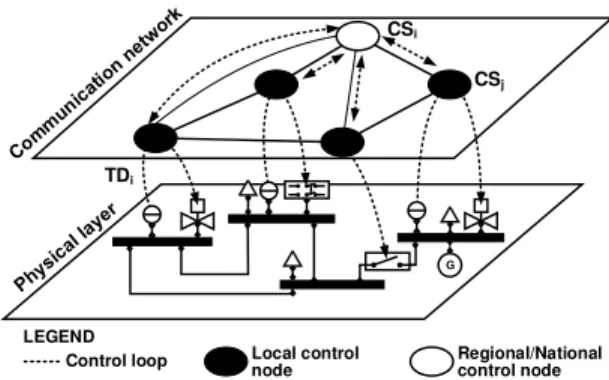
The architecture of modern ICS follows a hierarchical structure comprising of two different layers (see Fig. 1): (i) the physical layer, which encompasses a variety of sensors, actua-tors, and hardware devices that physically perform the actions on the system; (ii) and the cyber layer, which encompasses all the ICT hardware and software needed to monitor the physical process and to implement complex control loops. The size of ICS installations may vary from a few sensors and generic PCs to thousands of control objects, RFIDs, industrial equipment, and video surveillance cameras, organized in a hierarchical structure spread across a large geographical area.
Within such a composite technological ecosystem, control loops are provisioned at various network locations to carry out critical operations and to ensure the correct functioning of the underlying physical process. They may interact directly with sensor and actuator nodes, or remotely with other controllers in a hierarchical and distributed control system architecture, as the one depicted in Fig. 1. Essentially, control loops represent the core of ICS which need to be protected against malicious threats targeting the cyber and the physical dimensions of these critical infrastructures. Various ICS-specific cyber attacks have been elaborately studied by previous research. Real-world
G
LEGEND
Control loop Local control node Regional/National control node TDi CSj CSi
Fig. 1. Example ICS architecture.
examples such as the attack on the Maroochy Shire Council’s sewage system in Queensland, Australia [27], showed that unprotected ICS communications are highly susceptible to packet injection attacks. The Stuxnet malware [1], on the other hand, demonstrated that cyber attacks incorporating in-depth knowledge on the physical process can mount sophisticated attacks against ICS. These may alter legitimate control signals in order to cause important damages. Lastly, studies such as the one of Krotofil,et al.[26], showed that sensor data analysis may be used to infer the optimal time for launching Denial of Service attacks on control signals. These examples are clear evidence on the necessity to address the security requirements of ICS networks at early design phases.
Specific measures for strengthening the security of ICS have been proposed in recent guidelines and standards [3], [4]. In this work we focus on the concepts of SZC as defined by ISA-62443.03.02. Here, the grouping of physical or of logical assets into zones and conduits is usually the result of a high-level assessment delivering a ranking on the significance of cyber assets. However, the provisioning of SZC into the ar-chitecture of ICS must not affect the Quality of Service (QoS) requirements pertaining to the characteristics of industrial installations, e.g., strong determinism, real-time data transfer [28], [29]. In fact, accidental or deliberate changes of network conditions, e.g., delay and jitter, pose significant threats to the correct functioning of control loops and finally to the normal operation of physical process [30]. Therefore, QoS-specific requirements are essential factors in the provisioning of ICS networks which need to be encapsulated and harmonized with the complete set of ICS design prerequisites.
Faced with these challenges, in this work we undertake the ICS network design problem from the perspective of the aforementioned requirements. We assume that the physical process is supervised through a set ofobserved variables, and its behavior is regulated through a set of control variables. Control nodes may take various forms, yet the best known implementation is the dedicated control hardware. Neverthe-less, this work assumes that human operators are an integral part of ICS and may close significant control loops at a local, regional or national level by means of various ICT hardware and software. As a result, control loop end-points may include control nodes (in a simple or hierarchical structure), but also the measurement and the actuation nodes. Subsequently, we assume that end-points exchange data through network data
flows, hereinafter called traffic demands, a terminology that is adopted from the field of traditional ICT network design [16], [31]. Finally, we assume that traffic demands between end-points are routed by a communication infrastructure con-sisting of concentrator nodes positioned at feasible locations. Concentrators may route traffic between each other according to a given connectivity matrix. In this work the mathematical model of the ICS network design is formulated as an integer linear programming (ILP) problem. As described earlier in this section, demand routing paths, end-points, and concentrator sites need to be installed in such a way to minimize the costs of the infrastructure, while ensuring that constraints regarding real-time communications and security are satisfied.
A central part of the ILP problem is the identification of cyber security requirements for assets denoted by demands and their end-points. Accordingly, this work adopts a procedure inspired from the field of System Dynamics [8] in order to assess the impact of cyber attacks on the normal functioning of physical processes. The result of this procedure is a ranking of cyber assets which is interpreted as the set of security requirements. At the core of this approach is a technique that records the behaviorof complex ICS in the presence of accidental or deliberate interventions, e.g., faults, and cyber at-tacks. Essentially, the cyber attack impact assessment (CAIA) procedure calculates the co-variance of observed variables before and after the execution of an intervention. This provides a metric to quantify the significance of each control variable on the behavior of ICS and finally to rank demands and their end-points in the ILP problem at hand. Compared to state of the art, this technique is well suited for scenarios in which the process model is not available or in production systems in case control and measurement variable data series are available. The later case is particularly useful in post-event scenarios where the emphasis is placed on establishing the relative impact of specific faults and of cyber attacks. The mathematical foundation of the ICS network design problem builds on the traditional network design problem as formulated by Capone
et al.in [16]. However, the work presented in [16] is adapted
and expanded in order to accommodate characteristics of ICS networks and of ICS communications, and to integrate ICS security recommendations outlined in ISA-62443.03.02.
IV. ICS NETWORKDESIGNMODEL
This section expands the traditional ICS network design problem with security requirements aimed at constructing solutions to the design of modern ICS.
A. Preliminary Notations
1) Basic Sets and Costs: We defineI={1,2, ..., i, ...}to be the set of traffic demands (TD),J ={1,2, ..., j, ...}the set of potential concentrator sites (CS), and S ={1,2, ..., s, ...}
the set of potential security zone levels. Then, letcSj to be the
cost associated with installing CSj,cB
jl be the cost of buying
one unit of bandwidth between CSs j andl, cA
ij the cost of
buying one unit of bandwidth between the access end-point of TD iand CSj,cEjithe cost of buying one unit of bandwidth between the egress end-point of TD i and CS j, and cZ
js the
cost associated with installing zone s at CS j. It should be noted that we distinguish between access and egress end-points in order to ensure flexible and individual configuration of parameters. Therefore, their use is not limited to asynchronous, i.e., one-directional, flows. Instead, designers may use TDs as either uni-directional or bi-directional communication flows.
Finally, we define the costs associated with security con-duits. Let cC
jl be the cost associated with installing one
elementary security conduit between CSs j and l. The exact cost associated with a specific conduit level is then obtained by multiplying the selected level of conduit on link (j,l) with the cost of one elementary security conduitcC
jl.
2) Communication Infrastructure Parameters: Let di
de-note the TDi,ujl the link capacity between CSsj andl, and
vjthe access and egress demand capacity of CSj. Considering
the geographic location of access/egress end-points for each individual TD as well as the geographic location of CSs, the following binary connectivity parameters are defined. Letaij
be a binary parameter with value 1 if the access end-point of TDican connect to CSj,bjla binary parameter with value 1
if CS j can connect to CSl, andejia binary parameter with
value 1 if egress end-point of TDican connect to CSj.
3) Real-Time Requirement Parameters: With respect to
the ICS real-time performance requirements, the following communication latency parameters are defined. LetqA
ij be the
latency between access end-point of TD i and CSj, qEji the latency between CS j and egress end-point of TD i, qL
jl the
latency between CSsjandl, andqCj the latency introduced by each CSj. Finally, we define the maximum tolerated latency for each individual TDias qMi .
4) Security Zone and Conduits Parameters: Depending on
the outcome of the CAIA procedure, demand end-points are assigned specific security zone requirements. Therefore, we define rA
is as a binary parameter with value 1 if the access
end-point of demand i should be incorporated into a zone with security levels, andrEisas a binary parameter with value 1 if the egress end-point of demandi should be incorporated into a zone with security levels. Consequently, for each end-point designers may select more than one security zone, which ensures the creation of in-depth security architectures where security zones are recreated according to a layered approach [3]. The outcome of CAIA also identifies the necessary secu-rity conduit levels of each individual demand. Therefore, we define an integer parameterpito denote the minimum security
conduit level that needs to be installed for demandi. It should be noted that security levels associated to zones and conduits are identified by means of traditional assessment methodolo-gies that identify the criticality of devices and communica-tions, and the possible consequences of attacks. Accordingly, security devices including traditional firewalls, e.g., with port filtering enabled, next generation firewalls with packet inspec-tion and intrusion preveninspec-tion systems, as well as intrusion detection systems, and Virtual Private Networks (VPN) can be adopted in the definition of SZC. Their performances pertaining to traditional security characteristics such as the maximum throughput of stateful packet inspection, the number of concurrent firewall connections, the maximum site-to-site VPN sessions, are well defined in technical specifications and
can be used to identify the security parameters as required by the proposed ICS design model. Their associated costs, however, are vendor-specific and publicly available. Finally, we need to account for the capacity of security devices, e.g., firewall, and Intrusion Detection Systems, expressed most of the times in terms of traffic volume. Therefore, we define zs
to store the capacity of security devices installed in zones.
5) Variables: We definegj as a binary variable with value
1 if CSj is installed,xij as a binary variable with value 1 if
the access end-point of TD i is connected to CS j,wji as a
binary variable with value 1 if CSj is connected to the egress end-point of TD i, and ti
jl as a binary variable with value 1
if TD iis routed on link (j, l). We define one supplementary binary variableyjs to enforce that installation costs associated
with each zone sare added only once for each CSj if there is at least one TD end-point with security zone requirement s connected to CS j. Finally, we define the integer variable fjl to store the level of the security conduit installed between
CSs j andl. The range of values forfjl is lower and upper
bounded to the minimum and maximum conduit levels.
B. Objective Function
The objective function that minimizes the cost of the ICS installation is the following:
min X j∈J cSjgj+ X j,l∈J,i∈I cBjltijldi+ X j∈J,i∈I cAijxij+cEjiwji di+ X j∈J,s∈S cZjsyjs+ X j,l∈J cCjlfjl (1)
The objective function (1) accounts for the total installa-tion cost of security zones and concentrators, communicainstalla-tion links between CSs, and the total installation cost of security conduits. In particular, the term P
cSjgj is the total cost
of installing all selected CSs, the term P cB
jltijldi is the
total cost of bandwidth for routing TDs between CSs, and P
cA
ijxij+cEjiwjidi is the total cost of bandwidth for
access and egress end-points connected to CSs. The remaining two terms account for the cost of installing security measures: P
cZ
jsyjs is the total cost of installing security zones in the
premises of CS j; and P cC
jlfjl is the total cost of installing
security conduits between CSs j andl.
C. Constraints
The following constraints are defined:
1) Access/Egress End-Point Constraints:
X j∈J xij = 1, X j∈J wji= 1, ∀i∈I (2) xij ≤aijgj, wji≤ejigj, ∀i∈I, j∈J (3)
These constraints limit the number of connections between access/egress demand end-points and CSs to exactly one.
2) Flow Conservation Constraints:
xij−wji−
X
l∈J
tijl−tilj
= 0, ∀j∈J, i∈I (4) These denote classical multicommodity flow conservation constraints [32].
3) Concentrator Capacity Constraints:
X
i∈I
di(xij+wji)≤vj, ∀j∈J (5)
These constraints impose that for each concentrator the serviced ingress and egress traffic demands do not exceed the concentrators’ link capacity.
4) Concentrator Link Capacity Constraints:
X i∈I ditijl ≤ujlbjlgj, X i∈I ditijl≤ujlbjlgl, ∀j, l∈J (6)
These constraints impose that the total demand routed between each pair of connected CSsj andl does not exceed the installed link capacity.
5) Security Zone Constraints:
yjs≤ X i∈I rAisxij+rEiswji , ∀j∈J, s∈S (7) αZyjs≥ X i∈I risAxij+rEiswji , ∀j∈J, s∈S (8) These constraints ensure that the objective function (1) accounts for the cost of installing a security zone of level s at CS j only if there is at least one demand with an end-point connected to j for which designers defined a security zone of level s. More specifically, the first inequality forces yjs = 0 if P rAisxij+rEiswji
= 0, while the second inequality forces yjs = 1 if P risAxij+risEwji
≥ 1. αZ is a large integer parameter with a value greater than
maxP
i∈I,s∈S risAxij+rEiswji
,∀j ∈ J. Subsequently, the following constraints ensure that the capacity of security zone s, i.e., the capacity of security devices, is not exceeded:
X
i∈I
risAxij+rEiswjidi≤zs, ∀j∈J, s∈S (9) 6) Security Conduit Constraints:
fjl≥pitijl, fjl≤αCbjl ∀j, l∈J, i∈I (10)
These constraints force the selection of the maximum secu-rity conduit level between CSsjandl. Since demands with a specific conduit level may only be routed on a link implement-ing at least the same level of security conduit, these constraints impose the fulfillment of security conduit requirements for all demands routed on link(j, l). In particular, the first inequality defines the lower-bound of fjl which shall receive at least
the maximum value from all conduit levels pi routed on link (j, l). The second inequality, however, forces an upper-bound forfjl of the maximum conduit level ifbjl = 1, and of zero,
otherwise.αC is an integer parameter equal to the maximum level of security conduit, that is αC= maxpi,∀i∈I.
7) Real-Time Traffic Constraints:
X j∈J qijAxij+qEjiwji +X j,l∈J tijl qjlL+qjC + X j∈J qCjwji≤qMi , ∀i∈I (11)
These constraints force the selection of routing paths that fulfill the latency requirements defined for each demand. In particular, for each demand i, the term P
qA
is the sum of latencies for access and egress links, the term P
tijlqjlL+qjC is the sum of latencies owed to CSs and links between CSs, and the term P
qC
jwji is the latency of
the egress CS. These have been formulated in such a way that the execution of the objective function is not affected by their exclusion from the problem. This is a particularly significant aspect of network design since in real scenarios, especially at early design stages, the exact identification of all parameter values may not be feasible. Therefore, these should be viewed as an optional set of constraints, which are applied once all latency parameters have been appropriately measured.
D. Discussion
The proposed ICS model defines various parameters, which are essential for the completeness of the problem’s def-inition. Obviously, in practical scenarios human designers may encounter difficulties in identifying their precise values. However, it is noteworthy that the complete estimation of all parameters is not a prerequisite for running the proposed model. In fact, constraints have been deliberately categorized and ordered according to their significance. At early design stages it is essential to define the feasible connectivity pa-rameters and to run the model exclusively with constraints (2), (3), (4) activated. This solution can provide significant details on the approximate necessary bandwidth and node capacities. Then, capacity constraints (5), (6) can be activated and parameters may be further adjusted in order to better reflect the real performances of various devices. Once the possible connectivity and the capacity of devices are identified, designers may turn to assessment methodologies in order to estimate the security requirements of TDs. These will provide the data for activating security constraints (7), (8), (9), (10), and to obtain a security-enabled architecture. Finally, based on the solution generated so far designers can approximate the latency of communication links and can activate real-time traffic constraints (11). With this solution designers may revisit certain parameters in order to enhance the accuracy of results. These steps provide an effective strategy for designers to apply a complex, yet structured ICS network design model. It should be noted that with each set of constraints the solution may change (as demonstrated later by experimental results), and in some cases the problem may not be feasible. For the later extreme cases the following section defines relaxation conditions that impose an automated adjustment of capacity parameters with certain penalty costs. These constraints, i.e., (5), (6), are responsible for the distribution of connections among various CSs and may be seen as contradictory with re-spect to the objective function and to the remaining constraints, which aim at reducing the number of provisioned components. Therefore, by relaxing capacity constraints, an automatically adjustable balancing mechanisms is incorporated into the proposed problem, which can further aid engineers to correctly estimate parameter values.
V. ICS NETWORKDESIGNPROBLEMRELAXATION
Depending on the values of its input parameters, the pro-posed ILP may fail to construct a feasible solution that satisfies
all of the constraints. This is mainly a result of connectivity parameters aij, bjl, and eji, which can significantly reduce
the palette of feasible connection points, and, at the same time, may impose connection options exceeding the capacity of concentrator nodes governed byvjandujl. These assertions
are confirmed by the analysis conducted with the AIMMS tool and its implementation ofirreducible inconsistent system (IIS)identification [33]. An IIS is a subset of all constraints of an optimization problem that are self-contradictory. In other words, as soon as one of the constraints in the IIS is removed, the infeasibility is resolved. Owed to this analysis, we found that constraints (2), (3), (4), (5), and (6) may lead to an infeasible solution in case of insufficient bandwidth. In practice, however, instead of simply stopping execution it is preferable that the solver produces a feasible solution even if this entails additional penalties, i.e., additional costs.
Consequently, we revise the ICS network design problem by assuming that in case the solution is infeasible, additional bandwidth may be acquired with certain penalty costs. As such, we define cB+
jl to be the cost associated with buying
one supplementary unit of bandwidth between CSs j and l, and cV+
j the cost of buying one supplementary unit of
bandwidth for access and egress demand nodes connected to CS j. We further define the integer variable τjl to store the
supplementary bandwidth allocated between CSsj andl, and the integer variable ωj to store the supplementary bandwidth
allocated to CS j. As a result, the objective function that minimizes the cost of the ICS installation becomes:
min X j∈J cSjgj+ X j,l∈J,i∈I cBjltijldi+ X j∈J,i∈I cAijxij+cEjiwjidi+ X j∈J,s∈S cZjsyjs+ X j,l∈J cCjlfjl+ X j,l∈J cBjl+τjl+ X j∈J cVj+ωj (12) Compared to (1), the objective function (12) incorporates two additional terms: P
cB+
jl τjl is the sum of penalty costs
owed to buying supplementary bandwidth between CSsj and l, and P
cV+
j ωj is the sum of penalty costs owed to buying
supplementary bandwidth for demands connected to CS j. Finally, concentrator capacity constraints (5) and (6) are relaxed by incorporating variables ωj and τjl into their
defi-nitions, such that∀j∈J: X i∈I di(xij+wji)≤vj+ωj, (13) X i∈I ditijl≤(ujlgj+τjl)bjl, X i∈I ditijl≤(ujlgl+τjl)bjl (14)
VI. CYBERATTACKIMPACTANALYSIS
The description of the cyber attack impact assessment (CAIA) approach relies on the following definitions of sets:
T = {1,2, ..., k, ...m} is the set of measurements for each discrete time moment k, J = {1,2, ..., , ...n} is the set of observed variables, and I = {1,2, ..., ı, ...ρ} is the set of control variables. We define Yı, ı ∈ I as a bi-dimensional
matrix containing m measurements of n observed variables for an intervention applied on control variableνı. We useYkı
andYk0 to denote the k-th measurement of the -th observed variable for a scenario implementing a specific intervention and for a scenario without interventions, respectively.
Essentially, CAIA compares the values of observed vari-ables before and after the execution of a specific intervention by means of calculating the cross co-variance between mea-surement time series. Then, the method evaluates the relative impactℜı, ı∈ I, of the intervention on each control variable.
More formally, Equation (15) defines the mean value of the -th observed variable for interventions on the ı-th control variable (Y¯ı
) and the intervention-free mean value for the-th
observed variable (Y¯0 ): ¯ Yı= 1 m X k∈T Ykı,Y¯ 0 = 1 m X k∈T Yk0,∀ı∈ I,∀∈ J (15)
Then, the mean value of cross co-variances for the inter-vention on the ı-th control variable is defined as:
¯ Cı= X ∈J W X k∈T (Ykı −Y¯ı)(Ykj0 −Y¯0),∀ı∈ I (16) whereWis the weight, i.e., the importance, of changes in the
-th observed variable. This parameter ensures that CAIA can also be applied in domains, e.g., chemical, where observed variables contribute differently to the calculation of impact, e.g., according to their significance. The result of applying the CAIA procedure is a valueℜı, which ranks the impact of
intervention on theı-th control variable, and is defined as:
ℜı= ¯ Cı P ℓ∈I ¯ Cℓ ,∀ı∈ I (17)
Finally, the values ofℜıare used to initializerAisandrisEin
the ILP problem described in the previous section.ℜıallows a
human expert to select the necessary number of security zones and to define specific thresholds in establishing a cyber attack impact ranking. Depending on these thresholds, human experts may assign security zone and conduit levels to demands and end-points associated to each control variable. For example, in the particular case of energy grids control variables associated to high voltage circuit breakers may exhibit a higher impact ranking than low voltage circuit breaker’s control variables. This is highly intuitive since disturbances on high voltage bus lines may have a significantly larger impact on observed variables, e.g., voltage levels. As a result, control variables with higher impact values may require higher protection levels than low impact control variables. Nevertheless, it is up to the designer to establish the significance of variations in observed variables as well as their specific ranking. For this purpose multi-level ranking methodologies such as the Smart Grid Information Security (SGIS) levels [34] may also be adopted.
VII. EXPERIMENTALASSESSMENT
In this section we evaluate the sensitivity of the proposed ICS network design approach to different parameters like the installation costs, the number of demands, the number of candidate concentrator sites, and the security configuration of demands and of their end-points. We experimentally compare the performance of the CAIA procedure to related cyber
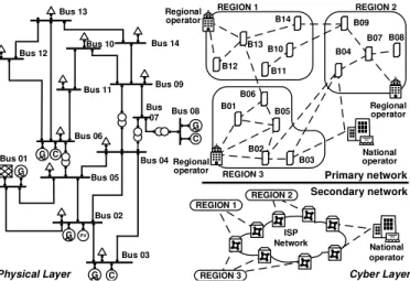
Physical Layer C Bus 03 Bus 02 Bus 01 Bus 05 Bus 04 Bus 07 Bus 09 Bus 11 Bus 06 Bus 14 Bus 10 Bus 12 Bus 13 PV C C G G G G G B12 B13 B14 B10 B11 B09 B07 B08 B04 B05 B01 B06 B02 B03 REGION 1 REGION 2 REGION 3 Regional operator Regional operator Regional operator ISP Network REGION 1 REGION 2 REGION 3 National operator Primary network Bus 08 Cyber Layer National operator Secondary network
Fig. 2. Experimental ICS architecture including the IEEE 14-bus model as physical process and the cyber layer with primary and secondary networks.
attack impact assessment techniques in order to illustrate the importance of control loops and the superior performance of the approach proposed in this work.
Numerical results are given for two different scenarios. First, a qualitative assessment is performed on a case involving the IEEE 14-bus model [35] (see Fig. 2) enriched with data obtained from a local Internet Service Provider (ISP) and a local electricity grid operator. Then, a quantitative assessment is performed on a generated large-scale network topology in order to test the scalability of the proposed technique.
In this work we implemented the network provisioning problem in AIMMS and we adopted the popular CPLEX engine as an ILP problem solver. MATLAB PSAT toolbox [36] was used for the simulation of the physical process model.
A. Scenario A: Qualitative Assessment
In order to ensure a realistic estimation of parameters we arranged meetings with representatives of a local electricity grid operator and a local ISP. Discussions revealed that at least in the case of Romania networking solutions in the industrial sector are far behind the quality of services offered by ISPs. Therefore, industrial operators tend to adopt advanced and reliable networking solutions offered by ISPs, which is a trend followed by other companies as well [37]. Based on these discussions, in the first scenario we adopt the IEEE 14-bus system enriched with control loops specific to real-world power systems such as Power System Stabilizer (PSS), Automatic Voltage Regulators (AVR) and Turbine Governors (TG). We assume an architecture of a large-scale installation structured in three different regions. In this scenario the munication network encompasses the company’s own com-munication lines based on fiber optics (primary network), and the communication channels leased from various national ISPs (secondary network), based on a mixture of wired and wireless networks (see Fig. 2). We further assume that REGION 1
(R1) coincides with a mountainous region where primary communication lines involve higher maintenance costs, com-pared to other regions. Nevertheless, connection alternatives are available from national ISPs.
TABLE I
INITIAL PARAMETER VALUES
Parameter Value
I, J, S {1,2, ...,34},{1,2, ...,26},{1,2}
cS
j [MU/Mb/s] 30
cB
jl[MU/Mb/s] 10 (R1), 3 (R2, R3), 1 (sec. net.) cA ij, cEji[MU/Mb/s] 1 cZ js[MU] 30 (s= 1), 300 (s= 2) cC jl[MU] 300 (R1), 30 (otherwise) cB+ jl , c V+ j [MU/Mb/s] 100 di[Mb/s] 30 (data), 10 (VoIP) ujl[Mb/s] 1000 (R1), 10000 (R2, R3), 1000 (sec. net.) vj[Mb/s] 8000 aij,bjl,eji[0-1] according to Fig. 2 qCj, qLjl, qijA, qEji[ms] 1 qM j [ms] 10 rA
is, rEis, pi[0-1] according to attack impact assessment zs[Mb/s] 1000 (s= 1), 6000 (s= 2)
pi[Integer] 1 (elementary conduit), 10 (advanced conduit)
1) Parameterization of the ILP Model: Table I lists the
initial set of parameter values in the numerical examples that follow. We assume that cSj = 30 monetary units (MU) for all CSs, which includes the provisioning of hardware and software solutions to enable in-place fundamental concentrator features. Subsequently, we adopt a differentiated distribution of bandwidth costs across regions and networks such that cB
jl= 10MU per Mb/s in R1, cBjl= 3MU/Mb/s inREGION 2
(R2) and REGION 3(R3),cB
jl= 1MU/Mb/s in the secondary
communication network, and cA
ij = cEji = 1MU/Mb/s. We
assume an increased penalty cost for supplementary bandwidth allocation ofcB+
jl =cV
+
j = 100MU/Mb/s, which encompasses
the provisioning of additional communication lines. For the sake of simplicity, we further assume two possible security zones such that cZ
js = 30MU when s= 1 for an elementary
security zone, andcZjs = 300MU whens= 2for an advanced
security zone which might include state of the art next generation firewall with Intrusion Detection and Prevention Systems enabled. The cost of an elementary security conduit is cC
jl= 300MU for R1 andcCjl = 30MU, otherwise.
Accordingly to the discussions with the electricity operator we assume the routing of two traffic demands from each substation to each regional operator and from each regional operator to a national operations center. The first demand is a high priority data channel encapsulating the physical process monitoring and control traffic, while the second demand is a lower priority, yet still critical channel, encapsulating Voice Over IP (VoIP) traffic. Therefore, in the present scenario we assume two different classes of traffic demands: one data communication demand ofdi= 30Mb/s, and one Voice Over
IP (VoIP) demand ofdi= 10Mb/s. We assume that a pair of
two such demands is routed between substations and regional operator centers, as well as between regional and national operator centers. With respect to the capacity of CS links we assume typical values learned from the two operators, that is ujl = 1000Mb/s in R1, ujl = 10000Mb/s in R2 and R3,
andujl= 1000Mb/s in the secondary network. Subsequently,
access/egress demand capacity of each CS isvj = 8000Mb/s.
Connectivity parameters aij, bjl, and eji are initialized
according to the connection options depicted in Fig. 2. For the sake of simplicity, the value of each communication latency parameter is of 1ms. The maximum tolerated latency qM
i is
10ms for real-time data [38] and 150ms for VoIP [39]. With respect to the capacity of security zones, we assume zs = 1000Mb/s when s = 1 and zs = 6000Mb/s when
s= 2. The values of risA, risE, pi are selected by means of the
cyber attack impact assessment performed in the following sub-section. Finally, we assume two distinct security conduits such thatpi= 1for an elementary conduit with basic security
features, and pi = 10 for a conduit with advanced security
measures. Specific conduit requirements for each demand are identified in the following sub-section.
Obviously, the above assumptions are general and do not affect the proposed ICS network provisioning model which is applicable to any network problem and topology. The given values constitute an initial set of parameters which are then modified according to the goals of the analysis that follows.
2) Cyber Attack Impact Assessment: We aim at evaluating
the applicability and effectiveness of the CAIA procedure in the context of the IEEE 14-bus model. Obviously, many different cyber attacks may be tested and, as shown by other studies as well [14], [24], [25], [26], [40], the attacker’s targets may vary according to his goals. Therefore, in general, the CAIA procedure might need to be applied several times for different ICS cyber asset and attacker goals in order to obtain a more accurate and complete solution. However, for the sake of simplicity, in this work we assume that the attacker’s goal is to induce bus-level failures by sending specially crafted com-mands to remotely controlled circuit breakers. These trigger significant disturbance that propagate over the electricity lines and may ultimately cause severe damages to distant devices. In particular, this scenario also gives us the opportunity to compare the result of CAIA with that of previous studies [25]. We applied the CAIA procedure on the IEEE 14-bus model with this attacker model, i.e., intervention, in the presence and in the absence of stabilizer and control devices. With the stabilizer and control devices in place, CAIA indicated that buses 1,2, and 9 are the most critical to the normal functioning of the electricity grid (see Fig. 3). This is explained by the fact that buses 1 and 2 are connected to high power generators equipped with active control devices, which greatly influence the evolution of voltage levels through the grid. In turn, bus 9 has a key position in delivering power from
69kV and 18kV areas to the 13.8kV area. As a result, from the perspective of network design, buses 1,2, and 9
are critical and demands involving these buses need to be placed in advanced security conduits and zones. Subsequently, given that ultimately national operating centers may affect the normal functioning of all buses, demands and their end-points comprising of regional and national operators need to be secured with advanced measures.
Conversely, without active control devices the results re-turned by CAIA are notably different. In this case buses 4
and5 are designated as the most critical, while buses1 and2
seem to be less significant. This is an important finding and proof of the fact that the size of ICS nodes, e.g., the number of
1 2 3 4 5 6 7 8 9 10 11 12 13 14 0 0.2 0.4 0.6 0.8 1 Bus number Relative Impact [0,1]
CAIA − with controllers CAIA − without controllers Bilis et al.
Fig. 3. Cyber attack impact assessment performed on the IEEE 14-bus model.
connections, is not necessarily a reflection of the importance of ICS nodes. In fact, we compared the output of CAIA with that obtained by applying the methodology proposed by Bilis
et al. [25] on the IEEE 14-bus model. It should be noted that
the method proposed in [25] builds on five centrality metrics adopted from graph theory and does not account for the role of each node. As shown in Fig. 3, the results of the method proposed by Bilis et al.exhibit a different distribution of the node’s significance. Obviously, since this approach applies exclusively node connectivity principles, it is more suitable for large-scale electricity grids. However, as shown by the results of CAIA, the significance of nodes is mainly given by their role and by the devices attached to these nodes, e.g., stability controllers, which may have a decisive role in guaranteeing the stability of industrial installations.
3) Effect of Installation Costs: We evaluate the effect of
bandwidth cost, of concentrator node installation cost, of security zone cost, and finally of security conduit installation cost on the performance of the ILP model.
P12 P13 P10 P11 P14 R1 P1 P6 P5 P2 P3 R3 P9 P7 P8 P4 NAT R2 S1 S3
(a) Initial parameter values.
P12 P13 P10 P11 P14 R1 P1 P6 P5 P2 P3 R3 P9 P7 P8 P4 NAT R2 S1
(b) Increased bandwidth costs. Fig. 4. Effect of increased bandwidth costs. Primary CSs, secondary CSs, regional CSs, national CSs, and TD end-points are represented with boxes, ellipses, diamonds, trapezoids, and circles, respectively.
At first, we look at the graph visualization of the solutions generated by the ILP model. With the initial parameter values listed in Table I communications are mainly routed through the secondary network (see Fig. 4a) since here cBjl= 1MU/Mb/s, compared tocBjl = 10MU/Mb/s in R1 and tocBjl = 3MU/Mb/s in R2 and R3. However, by increasing the bandwidth costs in the secondary network to cB
jl = 6MU/Mb/s, connections
in R2 and R3 are rearranged and traffic is routed through the less expensive primary network. Nevertheless, in R1 the secondary network is still the best choice for routing demands
0 50 100 150 200 250 300 20 40 60 80 100 120 140
Security conduit cost in R1 [MU/Mb/s]
Bandwidth cost lower bound in second network [MU/Mb/s]
Fig. 5. Effect of security conduit costs in R1 on the required bandwidth costs’ lower bound in the secondary network which is needed in order to ensure that demands are routed exclusively in the primary network.
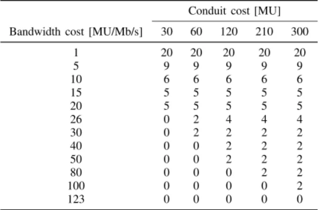
TABLE II
DEMANDS ROUTED IN THE SECONDARY NETWORK WITH RESPECT TO BANDWIDTH COSTS(SECONDARY NETWORK)AND CONDUIT COSTS(R1).
Conduit cost [MU]
Bandwidth cost [MU/Mb/s] 30 60 120 210 300
1 20 20 20 20 20 5 9 9 9 9 9 10 6 6 6 6 6 15 5 5 5 5 5 20 5 5 5 5 5 26 0 2 4 4 4 30 0 2 2 2 2 40 0 0 2 2 2 50 0 0 2 2 2 80 0 0 0 2 2 100 0 0 0 0 2 123 0 0 0 0 0
between substations and the regional operator. Next, we look at the effect of cost changes on the solutions generated by the ILP model. In particular, we analyze the effect of bandwidth and security conduit cost alterations on the selection of CSs. We aim to identify the necessary cost adjustments that may influence the selection of CSs from the secondary network. Recall that the cost of one elementary security conduit in R1 is ofcC
jl= 300MU, while the cost of conduits in the secondary
network is ofcCjl = 30MU (Table I). Therefore, our analysis focuses on the repeated reduction of conduit costs in R1 and on the increase of bandwidth costs in the secondary network. As shown in Table II both parameters have a significant impact on the number of demands routed in the secondary network. By increasing the cost of bandwidth units in the secondary network, the ILP model concludes that CSs from this network can be excluded from the solution only if cB
jl is at least
123MU for cC
jl = 300MU. Nevertheless, if cCjl = 30MU in
R1, then CSs from the secondary network are excluded if cB
jl is at least 26MU. The impact of costs on the solution,
and more specifically the linear interdependence between the cost of security conduits on the required bandwidth costs’ lower bound is also depicted in Fig. 5. As a final note, it is important to emphasize that irrespectively of the costs or of the chosen parameter values in general, the proposed ILP model ensures that critical real-time requirements formulated in terms of communication latency are satisfied at all times.
4) Effect of Security Configurations: We illustrate the effect of security configurations on the solution generated by the ILP model with the initial set of parameters from Table I. In the previous sections the CAIA procedure found that
P12 P13 P10 P11 P14 R1 P1 P6 P5 P2 P3 R3 P9 P7 P8 P4 NAT R2 S1 S3
(a) Elementary security con-duits. P12 P13 P10 P11 P14 R1 P1 P6 P5 P2 P3 R3 P9 P7 P8 P4 NAT R2 S1 S3
(b) Advanced security conduits. Fig. 6. Security zones and conduits. Simple dashed boxes denote advanced security zones, double dashed boxes denote two zones (elementary and advanced), while missing boxes denote elementary zones. Primary CSs, secondary CSs, regional CSs, national CSs, and TD end-points are represented with boxes, ellipses, diamonds, trapezoids, and circles, respectively.
communications with equipment installed on buses 1,2 and
9 require advanced security measures in terms of the pro-visioned conduits and zones associated with demands and their end-points. These requirements have been incorporated in the ILP model and the results have been illustrated in Fig. 6a and 6b. Here, the provisioning of advanced security zones is represented by dashed boxes, while the provisioning of elementary security zones is not highlighted with any particular symbol since all the remaining TD end-points are incorporated into elementary security zones. Conversely, the provisioning of elementary and advanced security zones (in case of regional operators) is represented by double dashed boxes. It can be seen that in both figures substation-level CSs denoted by P1, P2, and P9, as well as the national CS denoted by NAT, implement exclusively an advanced security zone, while regional CSs denoted by R1, R2, and R3 implement both elementary and advanced security zones. Conversely, CSs in the secondary network denoted by elliptic geometrical shapes do not implement security zones since they do not host direct connections from demand end-points. With respect to security conduits (Fig. 6b) it can be seen that advanced security conduits are implemented, according to the CAIA approach, specifically for the critical demands. As such, advanced security conduits are provisioned to protect TDs between P1 and R3,P2 and R3, P9 andR2, and between regional operator CSsR1, R2,R3and the national operators’ CSNAT. Elementary security conduits are provisioned for the remaining TDs (Fig. 6a). An important aspect, however, is that the ILP problem may route on the same link TDs with different security requirements. In such scenarios TDs are provisioned with the highest conduit level among the TDs selected on that particular link. In the present scenario this is visible in
REGION2, where the requirements of TDs connected to P9
have led to the provisioning of an advanced security conduit between CSsP9 andS3, and betweenS3 andR2. However, TDs with elementary conduit requirements between P4,P7, P8 on one hand andR2on the other hand are routed on the same advanced conduit installed between S3andR2.
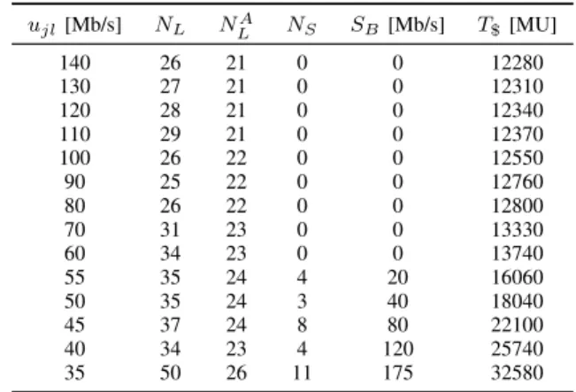
5) Effect of Link Capacity: We believe that the effect of
access/egress link capacity variations on the ILP solutions and
20 40 60 80 100 120 140 1 1.5 2 2.5 3 3.5x 10 4 Link capacity [Mb/s]
Installation cost [MU]
Fig. 7. Effect of link capacity variations between CSs on the total cost of the installation.
TABLE III
EFFECT OF LINK CAPACITY CHANGES ON THE GENERATED SOLUTION AND ON THE TOTAL COST OF THE INSTALLATION.
ujl[Mb/s] NL NLA NS SB[Mb/s] T$ [MU] 140 26 21 0 0 12280 130 27 21 0 0 12310 120 28 21 0 0 12340 110 29 21 0 0 12370 100 26 22 0 0 12550 90 25 22 0 0 12760 80 26 22 0 0 12800 70 31 23 0 0 13330 60 34 23 0 0 13740 55 35 24 4 20 16060 50 35 24 3 40 18040 45 37 24 8 80 22100 40 34 23 4 120 25740 35 50 26 11 175 32580
finally on the total cost of the installation is highly intuitive. In such cases the model allocates supplementary bandwidth in variable ωj for each CS j, which increases the total cost
by P ωjcV
+
j . Therefore, in the following, we look at the
effect of decreasing the capacity of links between CSs on: the total number of allocated links (denoted by NL); the
number of links with advanced security conduits (denoted by NLA); the number of links where supplementary bandwidth is allocated (denoted by NS); the total allocated supplementary
bandwidth (denoted bySB =Pτjl); and, the total cost of ICS
provisioning (denoted by T$). As depicted in Table III, the reduction of capacity on all links between CSs has a significant impact on the ILP solution. Starting fromujl= 140Mb/s and
down to ujl = 60Mb/s ∀j, l ∈ J the bandwidth deficiency
is mainly resolved by increasing the number of communi-cation lines from NL = 26 to NL = 34. Nevertheless, for
ujl = 100Mb/s the ILP model determines that it is more
cost-efficient to allocate an additional communication line with advanced conduit, rather than to increase the number of communication lines implementing elementary security conduits. Starting from ujl = 55Mb/s ∀j, l ∈ J, the ILP
model allocates supplementary bandwidth fromSB= 20Mb/s
forujl= 55Mb/s and up toSB = 175Mb/s forujl= 35Mb/s.
As a result, the penalties associated with the cost of supple-mentary bandwidth increase the overall cost of the installation fromT$= 13740MU up toT$= 32580MU. The effect of link capacity variations on the total cost of the installation is also depicted in Fig. 7. Here it can be seen that the penalty costs associated with supplementary bandwidth allocations have a
TABLE IV
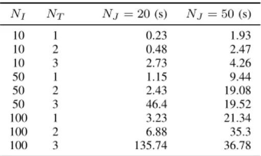
ILPMODEL COMPUTATION TIME.
NI NT NJ= 20(s) NJ= 50(s) 10 1 0.23 1.93 10 2 0.48 2.47 10 3 2.73 4.26 50 1 1.15 9.44 50 2 2.43 19.08 50 3 46.4 19.52 100 1 3.23 21.34 100 2 6.88 35.3 100 3 135.74 36.78
dramatic impact on the total cost of the installation.
B. Scenario B: Quantitative Assessment
We tested the performance of the ILP model in terms of CPU time on several ICS cases containing 20 and 50 CSs, 10, 50, and 100 TDs, and 1, 2, and 3 access/egress TD end-point connection choices to CSs. The network provisioning problem was implemented in AIMMS, and we measured the execution time of the CPLEX solver version 12.6. The tests were run on a Windows 7 PC with a 2.2 GHz Dual Core CPU and 4.0 GB of physical RAM. In the following, we use NI to denote the number of TDs, NJ to denote the number
of feasible CSs, and NT to denote the number of feasible
TD-CS links. Results are listed in Table IV. The computing time of the ILP model increases substantially with the size of the problem. As listed in Table IV, the performance of the ILP model is significantly influenced by NT. This is
explained by noting that NT affects the number of feasible
connections for access and egress end-points. Obviously, by imposingNT = 1, each TDs’ end-points are fixed to specific
CSs, in which case connection alternatives are not available. However, the increase of NT above one delivers at least one
connection alternative for each TD. Conversely, even though the computing time increases with the number of CSs, the additional CSs also bring new connection opportunities for TDs, which may decrease the overall computing time. For example, if NI = 50 and NT = 3 the computing time for
NJ = 20 is of 46.4s, while for NJ = 50 is of 19.52s. This
is explained by the behavior of ILP models where parameter changes do not necessarily lead to a proportional change in the problems’ solution, but rather to a new optimal solution.
Lastly, we test the effect of gradually activated constraints on the generated solutions. We assume a randomly generated network consisting of 30 CSs and 60 TDs. Parameter values are initialized according to Table I. At first, we exclusively enable connectivity constraints. Then, we gradually enable capacity constraints, security constraints, and finally real-time constraints. Given the significance of connectivity parameters, we assess the effect of their uniform distribution (20%-100%) on the generated solution. Assuming that solutions are char-acterized by the number of selected CSs, each configuration is run 10 times and the average number of CSs is computed. As denoted by the results in Fig. 8, the number of selected CSs depends on the connectivity parameters. By increasing the connectivity probability towards 100%, fewer CSs are
20 30 40 50 60 70 80 90 100 0 1 2 3 4 5 6 7 8 Connection probability (%) Concentrator count Conn Conn and Cap Conn, Cap and Sec Conn, Cap, Sec and RT
Fig. 8. Effect of gradually activated constraints on the generated solutions. Conn,Cap,Sec, andRTdenote connectivity, capacity, security and real-time constraints, respectively.
selected. However, by activating capacity constrains (we as-sume capacities of 300Mb/s) we observe an increase in the number of CSs. Security constraints on the other hand have a contrasting effect and cause a slight decrease in the number of CSs, which is the result of minimizing the cost of SZC. Finally, by activating real-time communication constraints, the number of selected CSs is further decreased in order to ensure that maximum latency requirements are satisfied. These results showcase the multi-phase characteristic of the proposed ICS network design methodology. In this respect constraints and their associated parameters are activated once their values are properly determined. On the other hand, the results also denote the importance of connectivity parameters, which need to be defined at early design stages. Such information, how-ever, depends on the exact installation characteristics and is available to network designers in the form of location and device characteristics. Based on preliminary results obtained with the configured connectivity parameters, network design-ers can then further approximate and enrich the ICS design methodology by activating additional constraints, as described in the previous sections.
VIII. CONCLUSION
We proposed an ILP problem to accommodate traditional ICS network design requirements and modern security recom-mendations outlined by the ISA-62443.03.02 standard. This approach saved costs on investments in the system’s resources, but also enhanced the security of ICS installations with state of the art requirements on security zones and security conduits. We additionally proposed a cyber attack impact assessment technique to rank the significance of cyber assets represented by traffic and communication end-points. The ICS network design methodology was extensively analyzed in a specific scenario involving the IEEE 14-bus model and a more general scenario with large-scale network topologies. It was shown that the approach minimizes the cost of the installation, while ensuring that both real-time constraints and security require-ments are satisfied. Results also proved that the technique is scalable and applicable to large ICS installations.
REFERENCES
[1] M. Hagerott, “Stuxnet and the vital role of critical infrastructure op-erators and engineers,” International Journal of Critical Infrastructure