Microarray Core UCSF Comprehensive Cancer Center
Standard Operating Procedure
Title: Loading Printing Plates with Spotting Solutions
SOP No.: MC 021
Version: 1
Date: 12-10-03
Page No.: 1 of 5
Authors: Oseroff
Reviewed: Bryd
This SOP allows the user to prepare appropriate printing plates for the UCSF-LBL custom microarray printing robot. Samples should have already been prepared as spotting (printing) solutions. If the spotting solutions have not yet been prepared, you may refer to SOP No. MC010: “Preparation of Spotting Solutions from BAC DNA.”
Contents; 1.0Materials 2.0Methods 3.0Notes
4.0Acknowledgements & References
1.0 Materials
1. Prepared spotting solutions.
2. 864-well polypropylene round bottom plate(s) (Whatman Inc. Cat. No. 7701-5033).
3. 96-well plate seal, (USA Scientific.(see Note 1)) 2.0 Methods
The layout of each printing plate depends on the type of print head used during a run. There are two available print heads for use: a 6-pin print head and 16-pin print head are both formatted for 864-well microtiter plates. (see Note 2) To determine which of the two print heads should be used, consider the number of spotting solutions, the number of spot replicates for each sample, and the placement of each spot with respect to one another. (see Notes 3 & 4)
2.1 Manual Transfer
A. 6-pin Print Head
1. Transfer each target into the 864-well microtiter plate according to the 3x2 tile format. (see Note 6) It is best to fill as many complete tiles as possible. 2. After one tile is filled with 6 different spotting solutions, continue either
horizontally or vertically along the plate. (see Note 5)
3. In order to prevent evaporation while loading, cut strips of a plate seal and cover the section of the plate already loaded.
4. To keep track of the 864-well location corresponding to each spotting solution, create an excel file that includes the clone’s library and the clone’s name and its link to a position in the 864-well plate. The larger the number of spotting solutions the more elaborate the excel file becomes to ensure tracking. (see Note 7)
5. When finished loading the plate cover it with a plate seal. (see Note 1) B. 16-pin Print Head
1. Transfer each spotting solution into the 864-well microtiter plate according to the 4x4 tile format. Complete each tile before moving on to the next. (see Note 6)
2. Continue the process of filling each tile either horizontally or vertically. 3. In order to prevent evaporation while loading, cut strips of a plate seal and
cover the section of the plate already loaded.
4. Record each transfer into the 864-well plate in an excel file, to keep track of clone location.
2.2 HYDRA Transfer
The hydra should be used to facilitate transferring spotting solutions from 96-well plates to 864-well plates. Nine 96-well plates are needed to completely fill an 864-well plate. Any fewer plates should be transferred manually to keep in accordance to the specified tile format.
1. Read through SOP No. MC 012 to understand how to run the HYDRA.
2. Create a program, or use a previously created program, that will transfer the solutions in each of the nine 96-well plate into one 864-well plate.
3. Run the program.
4. When the program is finished, remove the 864-well plate from the HYDRA stage and cover it with a plate seal.
5. Keep a record of the location of each clone in the 864-well plate. (see Note 8) 3.0 Notes
1. Depending on the type of solution in which the DNA is suspended, the plate seals will vary. If a chemical solvent, such as DMSO, is a component of the final solution, use a chemical resistant plate seal.
2. Each print head is custom made in compliance to the dimensions of the microtiter plate. In the case of an 864-well plate, each well is centered 3mm apart from its neighbor. Therefore the pins on an 864-well print head are separated by 3mm.
3. The 864-well 6-pin print head is an array of three columns and two rows of pins. The 864-well 16-pin print head is an array of four columns and four rows of pins. Each pin corresponds to one subarray in the microarray.
4. Spots of each subarray are placed within a 3mm separation minus the guard lane. In other words, the first spot of subarray 1 is separated by 3mm from the first spot of subarray 2. (see Figure 1 & Figure 2) The guard lane provides a control to prevent spots overlapping from adjacent subarrays. Each spot is placed equidistant apart. The following table lists how many spots one pin can print with a certain spacing, as well as the corresponding sample number/contiguous replicates/print head calculations:
Spacing (µm) Spots/Row/Pin Total Spots/Pin Spots in 6-pin Array Total Samples/3 Reps Spots in 16-pin Array Total Samples/3 Reps 100 28 784 4704 1512 12544 4032 125 22 484 2904 924 7744 2464 150 18 324 1944 648 5148 1728
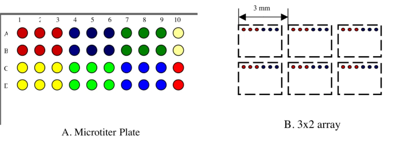
5. The 864-well 6-pin plate format combines six wells into an entity called a tile. The tile has the 3x2 layout as the print head. (see Figure 1) Although each tile can be filled to the user’s specification, the printing robot reads the location of the tiles from left to right. In addition it is easier for the individual setting up the print run to have a plate where the tiles are consecutive rather than dispersed throughout the plate.
Figure 1: A shows a partial 864-well plate with wells grouped into the 3x2 tile. Each tile is separated by a different color. B shows the layout of the microarray that a 6-pin print head will make.
6. The 864-well 16-pin plate format has sixteen wells for each tile. The tile has the 4x4 layout of the 16-pin print head. (see Figure 2)
1 2 3 4 5 6 7 8 9 10
A. Microtiter Plate B. 3x2 array
A
B
C
D
Figure 2: A shows a partial 864-well plate with wells grouped into the 4x4 tile. Each tile is separated by a different color. B shows the layout of the microarray a 16-pin print head will make
7. This excel file, along with the output file created by the printing robot will be used to make the sproc files to identify each spot on the array. The following is the top row of the excel file including all of the data needed:
8. Nine 96-well plates go into one 864-well plate. The HYDRA loads each 96-well plate in a pattern, such that one loading needle will transfer 9 different spotting solutions into a 3x3 tile. For example in the first transfer, pin 1 will transfer from A1 well of the 96-well plate into A1 well of the 864-well plate. Pin 2 will transfer from A2 well of the 96-well plate into the A4 well of the 864-well plate, and so on. In the second transfer, pin 1 will transfer from A1 well of the second 96-well plate into A2 well of the 864-well plate. Pin 2 will transfer from A2 well of the second 96-well plate into the A5 well of the 864-well plate, etc.
4.0 Acknowledgements
Hydra Operating Instructions
1 2 3 4 5 6 7 8 9 10 A. Microtiter Plate B. 4x4 array A B C D 3 mm