Flat Panel Display
Interface Technologies
White P
Joshua Larson-Mogal, Silicon Graphics, Inc.
In 1998, we have seen a revolution in the flat panel monitor market. Rapid price decreases have taken flat panel monitors (FPMs) from their elite, expensive niche and enabled broad adoption by consumer markets. Every major computer manufacturer now either has a flat panel monitor offering on the market or will with-in a few months. Part of the reason for this is the with-increaswith-ing popularity of mobile devices. With notebook
computers now representing almost 20 percent of the overall computer market1demand for and production
of flat panels are increasing at breakneck speed. Increased fabrication capacity in Japan, Korea, and Taiwan is opening the door not only to more and larger laptops (15.1-inch portables are now showing up), but to desktop flat panel monitors as well.
The term “flat panel” is most commonly used as a reference to liquid crystal displays, or LCDs. These dis-plays are fabricated using semiconductor processes, with each pixel being composed of transistors arranged in a rectangular grid. LCDs are inherently digital displays. In their most common computer application, note-book computers, LCDs have always been driven digitally. Inside the notenote-book computer, video drivers take the digital information in the graphics frame buffer and digitally interface to the row and column drivers that set the colors at each pixel in the display.
This differs dramatically from the traditional desktop computer. Desktop graphics subsystems typically include a graphics accelerator chip that renders an image into a digital frame buffer much the same as is done in the notebook computers. Before sending this image on to the display, however, the digital data is fed through an digital-to-analog (D-to-A) converter that converts the digital image data in the frame buffer into a serial analog stream. This stream is sent over the video cable, then read by the controller in an analog, cath-ode-ray tube (CRT) monitor and used to deflect the electron gun horizontally and vertically to stimulate spe-cific red, green, and blue phosphors to paint the image onto the screen.
CRTs: Input Resolution vs. Displayed Resolution
The natural blurring of the phosphors aids in hiding slight errors in the precision of scanning out the image onto the screen while an internal shadow mask between the gun and the phosphors ensures that the correct phosphors are hit (more or less). It should be noted that the resolutions that a multifrequency monitor can accept as input are different from the resolutions that it can actually display.
While many 19-inch monitors can accept signals with resolutions ranging from 640x480 red, green, blue (RGB) pixels to 1600x1200 RGB pixels, not all of them actually have the resolution in the shadow mask or phosphor grid to display each individual pixel at the highest resolution(s). The signals are handled properly and an image is displayed that appears correct, but switching to an image that alternates between black and white for each adjacent pixel will show only gray at the highest resolution. The problem lies in the fact that the shadow mask and phosphor layout may be such that the actual maximum resolution that can be resolved into individual phosphor triads (RGB) may be lower than the resolution that the electronics can accept and drive the electron gun.
Flat Panel Display Interface Technologies
1
IDC Research study: Personal Systems: Customer Directions and Buying Behavior: The 1996 Portable Computer Survey, May 1996, Randy Giusto.
This analog interface has proven to be very versatile and has enabled personal computers to increase their resolu-tion from 640x480 (VGA) to 1600x1200 (UXGA) over the past decade while retaining the same video connector. The consistency in the use of the 15-pin VGA connector has enabled the monitor industry to focus on innovation in image quality and resolution in both the displays themselves and in the CRT controllers that they build into the displays. Display manufacturers utilize this con-nector to ensure compatibility with virtually every graph-ics add-in card made for personal computers. Graphgraph-ics accelerator card manufacturers and systems manufactur-ers utilize this same connector to ensure that they are compatible with the maximum number of products and suppliers for their display needs.
Now, flat panel monitors are becoming a force in the display industry. Compaq, IBM, and others include FPMs in virtually every systems advertisement, and costs
have dropped to the point where FPMs that just a year ago cost six times as much as comparably sized CRTs now cost just over two times as much. This price drop is having virtually the same effect on FPMs that the drops in the prices of CPUs, disks, and memo-ry are having on the entmemo-ry-level PC market.
Analog Flat Panel Interfaces
To maximize the opportunity for flat panels, many manu-facturers have elected to include analog interfaces for their FPMs, ensuring that any FPM could be plugged into the standard output of any PC (or Macintosh®). This is an extremely convenient interface that, while it costs more than a standard digital interface, ensures the maximum compati-bility between the FPM and the various computers to which it might be attached. But since the panel itself is digital, the analog signal from the computer must be reconverted back to digital, and a pixel clock must be re-created to be able to control the line and column drivers of the LCD module.
As indicated in Figure 3, the digital data in the graphics frame buffer is converted to analog, for transmission across the cable, then reconverted back to digital to drive the display. Along the line, two things happen. As with virtually any conversion process, quality is degraded and information is lost. In this case, the key item of lost information is the pixel clock. To accommodate this issue, the analog interface circuitry within the dis-play attempts to re-create the pixel clock from Sync and other information in the analog video signal.
Electron gun
Deflection yoke
Grille
Screen
Figure 1: CRT Construction
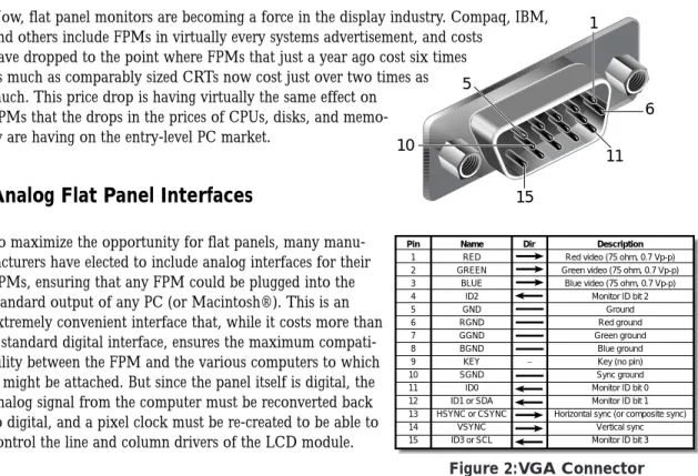
Figure 2:VGA Connector
5 1 10 15 11 6 Pin 1 2 3 4 5 6 7 8 9 10 11 12 13 14 15 Dir Description
Red video (75 ohm, 0.7 Vp-p) Green video (75 ohm, 0.7 Vp-p)
Blue video (75 ohm, 0.7 Vp-p) Monitor ID bit 2
Ground Red ground Green ground
Blue ground Key (no pin) Sync ground Monitor ID bit 0 Monitor ID bit 1 Horizontal sync (or composite sync)
Vertical sync Monitor ID bit 3 Name RED GREEN BLUE ID2 GND RGND GGND BGND KEY SGND ID0 ID1 or SDA HSYNC or CSYNC VSYNC ID3 or SCL
The Limits of
Analog Interfaces
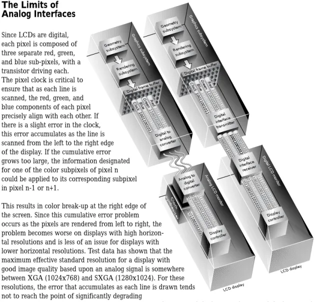
Since LCDs are digital, each pixel is composed of three separate red, green, and blue sub-pixels, with a transistor driving each. The pixel clock is critical to ensure that as each line is scanned, the red, green, and blue components of each pixel precisely align with each other. If there is a slight error in the clock, this error accumulates as the line is scanned from the left to the right edge of the display. If the cumulative error grows too large, the information designated for one of the color subpixels of pixel n could be applied to its corresponding subpixel in pixel n-1 or n+1.This results in color break-up at the right edge of the screen. Since this cumulative error problem occurs as the pixels are rendered from left to right, the problem becomes worse on displays with high horizon-tal resolutions and is less of an issue for displays with lower horizontal resolutions. Test data has shown that the maximum effective standard resolution for a display with good image quality based upon an analog signal is somewhere between XGA (1024x768) and SXGA (1280x1024). For these resolutions, the error that accumulates as each line is drawn tends not to reach the point of significantly degrading
the rendered image.
If the value of a flat panel monitor lies in its lack of flicker, better image quality, and more compact form, customers are only likely to spend the additional money that FPMs cost if image quality is a priority for their application. Thus, as resolutions of flat panels extend from 1280x1024 today2to 1600x1200 in the next
year, LCDs will more and more be in a position to displace CRTs. Unfortunately, these higher resolutions cannot avoid the pixel clock errors inherent in the analog signal and thus could never have the image quality demanded by professionals in desktop publishing, digital content creation, and other markets that require large resolutions and excellent image quality.
Digital Flat Panel Interfaces
The alternative, of course, is to drive these displays digitally from one end to the other. By maintaining a digi-tal signal from the graphics subsystem to the display drivers, there is no signal or clock degradation and image quality is ensured. Ensured, in this case, means that the digital signal itself does not suffer from noise,
2
The IBM 9516 and NEC LCD2010 flat panel monitors have 1280x1024 resolution, analog.
Figure 3: Digital to Analog to Digital Data Flow
Analog LCD monitor Red Green Blue Clock 101110011010101001 11001010011010101001 10100110011010101001 10011001011010101001 Digital to analog converter Digital frame bufferLCD display Analog to digital converter Clock synthesizer 10111001101010100101 11 001010011010101001 10 100110011010101001 10 01 1001011010101001 Display controller Geometry subsystem Rendering subsystem Graphics subsystem Digital LCD monitor Red Green Blue 101110011010101001 11001010011010101001 10100110011010101001 Clock 10011001011010101001 100010110101010011001100101101010100110011001011010101001100110010110101010011 101001011010101001 Digital interface transmitter Digital frame buffer
Digital interface receiver10111001101010100101 11 001010011010101001 10 100110011010101001 10 01 1001011010101001 LCD display Display controller Geometry subsystem Rendering subsystem Graphics subsystem
sampling errors, or excessive skew. A number of different solutions for communicating this digital signal exist. To date, there remains no industry consensus on a standard, but several have been proposed by and to VESA, the Video Equipment Standards Association. In Japan, a separate standards organization, the Japan Electronics Industry Display Association (JEIDA), is working on the Display Interface Standard for Monitors (DISM), a standard that is trying to distill a single solution from no less than six different protocols. In the United States and Europe, there are really only two protocols under serious consideration, but even within a given protocol, there is not consensus on the connectors, pin-outs, or cables to be used as compo-nents of the solution. The key protocols being considered today are very similar in many ways and yet very different in others. In either protocol, the primary goal is to convert TTL signals coming from the digital frame buffer into a signal that can be transmitted a certain distance, and then receive that signal at the dis-play end of the cable and convert the data back into TTL form.
Protocols and Standards
Protocols
The two key protocols are low voltage differential signaling (LVDS) and transition minimized differential sig-naling (TMDS). LVDS is an open standard defined by two key organizations, the American National Standards Institute/Telecommunications Industry Association/Electronic Industries Association (ANSI/TIA/EIA) and the Institute for Electrical and Electronic Engineering (IEEE). The baseline
ANSI/TIA/EIA-644 standard, approved in November 1995, serves as a foundation for the specific implemen-tation of LVDS as an interface to digital displays. The IEEE standard utilized LVDS as an interface for multi-processor interconnects and was ratified as IEEE 1596.3 in March 1996.
While very similar to LVDS in concept, TMDS is very different in execution. Begun as PanelLink, a propri-etary specification defined by Silicon Image, Inc., TMDS is the generic definition of PanelLink interface tech-nology. VESA is currently exploring the definition of TMDS as an open standard, but today it remains pro-prietary to Silicon Image.
Digital Display Standards
Today there exist three primary standards proposals leveraging these protocols, each proposed through differ-ent organizations. All hope to consolidate their standards through VESA evdiffer-entually, but they are not all in agreement with the direction VESA is heading with their standard proposal. The other two organizations are the Digital Flat Panel Group and the Visual Interface Consortium, International (VICI).
The DFP Group is a working group formed by a collection of companies to accelerate the establishment of a digital flat panel standard to quickly build a commercial market for digital FPMs. VICI includes representa-tives from a collection of companies and organizations focused on the definition of standards that enable innovation in visual interfaces, including but not limited to digital flat panels.
As a reference for resolutions referred to in the following standards discussions, Table 1 maps each supported resolution to its common name.
Table 1: Resolution Naming Scheme
The proposed standards are:
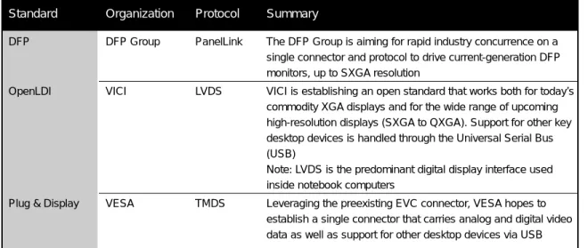
Standard Organization Protocol Summary
DFP DFP Group PanelLink The DFP Group is aiming for rapid industry concurrence on a single connector and protocol to drive current-generation DFP monitors, up to SXGA resolution
OpenLDI VICI LVDS VICI is establishing an open standard that works both for today’s commodity XGA displays and for the wide range of upcoming high-resolution displays (SXGA to QXGA). Support for other key desktop devices is handled through the Universal Serial Bus (USB)
Note: LVDS is the predominant digital display interface used inside notebook computers
Plug & Display VESA TMDS Leveraging the preexisting EVC connector, VESA hopes to establish a single connector that carries analog and digital video data as well as support for other desktop devices via USB
Table 2: Digital Flat Panel Standards
Goals for a Digital Standard
Before selecting any of the protocols or connector standards on the market, it is critical to explore the requirements driving the need for such a standard. These needs fall into two related categories: Business requirements that ensure the market viability of products based upon the standard and technical requirements that ensure that the standard can achieve the market goals.
Business
• Low cost of implementation
• Components available from multiple vendors to reduce risk • High reliability to minimize support costs
• Support for wide range of displays, from monitors to projectors • Support for wide range of resolutions, from commodity to high end • Long-term viability to minimize required ongoing technical investment
Resolution Name Horizontal Resolution x Vertical Resolution
VGA 640x480 XGA 1024x768 SXGA 1280x1024 UXGA 1600x1200 HDTV 1920x1080 HDTVplus 1920x1200 QXGA 2048x1536
Technical
• Low or nonexistent bit-error rate
• Data bandwidth to support resolutions from VGA to HDTVplus and beyond • Minimal skew to allow significant cable lengths (10m+) with nondegraded signals • Flexibility in the specification to allow for innovation
• Clearly licensed intellectual property (IP) to avoid litigation risk
To achieve broad, long-term success in the market, the successful standard will have to address all of these business and technical requirements.
In particular, a generic ranking of the requirements would probably look like the following: • Meet the resolution and cable length requirements… it has to work
• Low-risk implementation… it can’t stop a production line • Low-cost implementation… it has to make economic sense
Comparing the Interfaces
Business Factor Component OpenLDI PanelLink
Low cost Interface ICs Single chip transmitter Single chip transmitter supports resolutions supports resolutions from VGA to HDTVplus from VGA to SXGA Connectors <$1 DFP: < $1
P&D: $1 - $2 Cables 0-10 meters 0-3 meters
Shielded twisted pair Shielded twisted pair <$0.50 linear foot <$0.50 linear foot
3-10 meters Twin-axial ~$1 linear foot Multiple sources Interface ICs National, TI, Thine Silicon Image
Connectors 3M, AMP, Molex, DFP: 3M Harding P&D: Molex Cables 3M, Ultraflex 3M
Business Factor OpenLDI PanelLink
High reliability Bit rate tested up to UXGA at 5 Tested to SXGA at 5 meters
meters Since DFP and P&D specify only a single channel of PanelLink, data rates exceed 1 GHz per line pair beyond SXGA resolution. The reliability achievable at these rates is unknown
Support wide Single channel: Single channel only:
range of VGA to SXGA, 24 bit VGA to XGA w/24 bit color SXGA supported
resolutions Dual channel: in upcoming parts
XGA to HDTVplus, 24 bit
Long-term Currently supported resolutions Given PanelLink’s single-channel
viability with either one or two channels implementation, going beyond SXGA will
of LVDS cover all planned require scaling data rates well beyond 1 GHz display products for the next per line pair, unclear viability
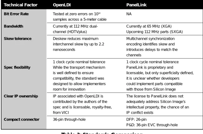
Technical Factor OpenLDI PanelLink
Bit Error Rate Tested at zero errors on 1014 NA
samples across a 5-meter cable
Bandwidth Currently at 112 MHz dual- Currently at 65 MHz (XGA)
channel (HDTVplus) Upcoming 112 MHz parts (SXGA)
Skew tolerance Deskew reduces maximum Multichannel synchronization
interchannel skew by up to 2.2 encoding identifies skew and nanoseconds introduces delays to match the
channels
1 clock cycle nominal tolerance 1 clock cycle nominal tolerance
Spec flexibility While the transport mechanism PanelLink is proprietary and
is well defined to ensure licensable, but only superficially defined, compatibility, the standard was it is unclear whether developers designed to allow implementers could implement parts compatible room for innovation with those from Silicon Image
Clear IP ownership IP associated with OpenLDI is The license to PanelLink does not
contributed by the authors of the adequately address Silicon Image’s spec and is licensable, royalty-free, intellectual property, the chance of an from VICI IP conflict exists
Compact connector 36-pin through-hole DFP: 26-pin
P&D: 36-pin EVC through-hole
Table 3: Standards Comparison
Summary
All told, there are compelling reasons to choose each of the standards solutions currently available. P&D is supported by a major standards organization, but requires a more expensive connector than the others. DFP is expedient, but has the downside of not supporting resolutions beyond XGA today or beyond SXGA in the near future. OpenLDI, while not proffered by VESA, is, nonetheless, an interesting option. Its ability to pro-vide compatibility between the new flat panel monitor world and the existing notebook computer world is particularly compelling, as is its multisource availability and single/dual channel flexibility, supporting resolu-tions which DFP and P&D cannot currently, and may not in the future, handle.
To learn more
Silicon Graphics, Inc. VESA National Semiconductor
www.sgi.com www.vesa.org www.national.com
Texas Instruments DFP Group VICI
©1998 Silicon Graphics, Inc. All rights reserved. Specifications subject to change without notice. Silicon Graphics and the Silicon Graphics logo are registered trademarks. Macintosh is a registered trademark of Apple Computer, Inc. All other trademarks men-tioned herein are the property of their respective owners.
1836 (6/98) Corporate Office 2011 N. Shoreline Boulevard Mountain View, CA 94043 (650) 960-1980 URL: http://www.sgi.com U.S. 1(800) 800-7441 Europe (44) 118-925.75.00 Asia Pacific (81) 3-54.88.18.11 Latin America 1(650) 933.46.37 Canada 1(905) 625- 4747 Australia/New Zealand (61) 2.9879.95.00 SAARC/India (91) 11.621.13.55 Sub-Saharan Africa (27) 11.884.41.47