ETSI TS 102 465
V1.1.1
(2006-12)
Technical Specification
Satellite Earth Stations and Systems (SES);
Broadband Satellite Multimedia (BSM)
General Security Architecture
Reference
DTS/SES-00105
Keywords
broadband, interworking, IP, satellite, security
ETSI
650 Route des Lucioles
F-06921 Sophia Antipolis Cedex - FRANCE
Tel.: +33 4 92 94 42 00 Fax: +33 4 93 65 47 16
Siret N° 348 623 562 00017 - NAF 742 C Association à but non lucratif enregistrée à la
Sous-Préfecture de Grasse (06) N° 7803/88
Important notice
Individual copies of the present document can be downloaded from:
http://www.etsi.org
The present document may be made available in more than one electronic version or in print. In any case of existing or perceived difference in contents between such versions, the reference version is the Portable Document Format (PDF). In case of dispute, the reference shall be the printing on ETSI printers of the PDF version kept on a specific network drive
within ETSI Secretariat.
Users of the present document should be aware that the document may be subject to revision or change of status. Information on the current status of this and other ETSI documents is available at
http://portal.etsi.org/tb/status/status.asp
If you find errors in the present document, please send your comment to one of the following services:
http://portal.etsi.org/chaircor/ETSI_support.asp
Copyright Notification
No part may be reproduced except as authorized by written permission. The copyright and the foregoing restriction extend to reproduction in all media.
© European Telecommunications Standards Institute 2006. All rights reserved.
DECTTM, PLUGTESTSTM and UMTSTM are Trade Marks of ETSI registered for the benefit of its Members.
TIPHONTM and the TIPHON logo are Trade Marks currently being registered by ETSI for the benefit of its Members.
Contents
Intellectual Property Rights ...5
Foreword...5
Introduction ...5
1 Scope ...6
2 References ...6
3 Definitions
and
abbreviations...6
3.1 Definitions ...6
3.2 Abbreviations ...7
4
BSM Security Service Requirements ...8
4.1 Threats to BSM and counter measure requirements...9
4.1.1 Network threats...9
4.1.2 Software threats ...10
4.1.3 Hardware threats ...10
4.1.4 Human threats ...10
4.2 BSM security services definition...11
4.3 Security related satellite characteristics...11
4.4 Security association scenarios ...12
4.4.1 End-to-End security ...12
4.4.2 Gateway-to-Gateway security...13
4.4.3 Combined host and gateway security...14
4.4.4 Remote host to gateway security ...15
4.5 ITU-T Recommendations - X.805 security architecture ...15
4.6 Summary of security service requirements...16
5
BSM Security Functional Architecture Requirements ...17
5.1 Security reference framework ...17
5.1.1 Data handling (privacy and integrity) ...19
5.1.2 Key management ...19
5.1.3 Security policy establishment and enforcement...19
5.1.4 Security association description...20
5.1.5 BSM security functional elements ...21
5.2 BSM Generic Protocol Architecture ...21
5.3 Interactions between security and other non BSM entities...23
5.3.1 Using COPS for security policy provisioning...23
5.3.2 Radius/ Diameter ...23
5.3.3 Interactions between BSM security and Network Address Translation (NAT)...24
5.4 Interactions between security and Performance Enhancing Proxies (PEP)...24
5.5 Summary of Security Architecture Requirements ...26
6
BSM security Functional Architecture Definition ...26
6.1 Detailed BSM security functional architecture...26
6.1.1 Case 1: IPsec and security entities in BSM...27
6.1.2 Case 2: Mixed link layer security entities in BSM (security manager above SI-SAP and security engine below SI-SAP) ...28
6.1.3 Case 3: End-to-end security ...29
6.1.4 Case 4: Pure link layer security ...30
6.2 Generalized interactions between security and other BSM entities...30
6.3 Interactions between security and QoS entities ...32
6.3.1 Security of QoS signalling in BSM network ...32
6.3.2 Using COPS protocol for security policy provisioning ...34
6.3.3 Using reliable transfer mechanisms (QoS) to transfer key management messages ...36
6.4 Interactions between security and address resolution entities ...36
6.4.1 Security of address resolution signalling in BSM network...36
Annex A (informative): Existing Security Technologies ...38
A.1 Introduction ...38
A.2 Link layer – ATM and DVB ...39
A.2.1 ATM security ...39
A.2.2 DVB-S conditional access...39
A.2.3 DVB-RCS security ...40
A.3 Network layer - IPsec ...40
A.4 Transport layer - SSL/TLS ...41
A.5 Application
layer
security ...42
A.6 Choosing a security technology ...42
Annex B (informative): Bibliography ...45
Intellectual Property Rights
IPRs essential or potentially essential to the present document may have been declared to ETSI. The information pertaining to these essential IPRs, if any, is publicly available for ETSI members and non-members, and can be found in ETSI SR 000 314: "Intellectual Property Rights (IPRs); Essential, or potentially Essential, IPRs notified to ETSI in
respect of ETSI standards", which is available from the ETSI Secretariat. Latest updates are available on the ETSI Web
server (http://webapp.etsi.org/IPR/home.asp).
Pursuant to the ETSI IPR Policy, no investigation, including IPR searches, has been carried out by ETSI. No guarantee can be given as to the existence of other IPRs not referenced in ETSI SR 000 314 (or the updates on the ETSI Web server) which are, or may be, or may become, essential to the present document.
Foreword
This Technical Specification (TS) has been produced by ETSI Technical Committee Satellite Earth Stations and Systems (SES).
Introduction
Based on the finding of Security Aspects report in BSM TR 102 287 (see bibliography) and the need for providing security services within the BSM systems and interworking with the outside world, there is a need for a BSM security management functional entities. These entities may reside above or below the Satellite Independent - Service Access Point (SI-SAP) and defines how data are secured through the BSM. IABG final report. ESA project (see bibliography) provides further information about similar issues.
The BSM, security management functions are defined for data handling, key management and security policy establishment and enforcement.
Although some satellite security specific systems exist today such as DVB-S and DVB-RCS, the main focus of the architecture definition will be on end-to-end security and between satellite terminals and Gateways plus interaction with satellite independent systems such as IPsec and upper layers security systems.
1 Scope
The present document defines the security management architecture based on the generic BSM architecture TS 102 292 (see bibliography).
The present document defines the BSM functional architecture required to provide security services to the end user and satellite networks. This architecture identifies the functional elements to allow security provision in BSM systems integrated with heterogeneous networks. Such elements will include secure data handling, key management and security policy handling. Interactions with Performance Enhancing Proxies and IPsec are also addressed.
Secure multicast is not addressed in the present document, however the mechanisms proposed in the present document may apply to multicast services. However, security architecture issues related to star and mesh topologies are addressed including the user, control and mgmt planes.
Securing management and control messages including OBP management are out of scope for the present document.
2 References
The following documents contain provisions which, through reference in this text, constitute provisions of the present document.
• References are either specific (identified by date of publication and/or edition number or version number) or non-specific.
• For a specific reference, subsequent revisions do not apply.
• For a non-specific reference, the latest version applies.
Referenced documents which are not found to be publicly available in the expected location might be found at
http://docbox.etsi.org/
NOTE: While any hyperlinks included in this clause were valid at the time of publication ETSI cannot guarantee their long term validity.
[1] ETSI ETR 232: "Security Techniques Advisory Group (STAG); Glossary of security terminology".
3 Definitions
and
abbreviations
3.1 Definitions
For the purposes of the present document, the terms and definitions given in ETR 232 [1] and the following apply: active attack: realization of an active threat
active threat: threat of a deliberate unauthorized change to the state of the system
authentication: property by which the correct identity of an entity or party is established with a required assurance authentication server: typically a RADIUS/DIAMETER server or others against which the users will authenticate and from which they can even receive their authorization rules
authenticator: access device or gateway, which is typically a switch or an access-point or a hub. The device in an authentication system that physically allows or blocks access to the network
authorization: permission granted by an owner for a specific purpose
aonfidentiality: avoidance of the disclosure of information without the permission of its owner countermeasures: security services or mechanisms designed to counter a particular threat
cryptographic key: parameter used with an algorithm to validate, authenticate, encrypt or decrypt a message
hash / message digest: mathematical formula that converts a message of any length into a unique fixed-length string of digits (typically 160 bits) known as "message digest" that represents the original message
NOTE: A hash is a one-way function - that is, it is unfeasible to reverse the process to determine the original message. Also, a hash function will not produce the same message digest from two different inputs. digital signature: electronic signature that can be used to authenticate the identity of the sender of a message, or of the signer of a document
NOTE: It can also be used to ensure that the original content of the message or document that has been conveyed is unchanged.
digital certificates: electronic document that establishes your credentials when doing business or other transactions on the web. They are issued by a certificate authority and contain a user"s name, expiration dates, a copy of the certificate holder"s public key, and the digital signature of the certificate-issuing authority so that a recipient can verify that the certificate is real. Some digital certificates conform to a standard such as X.509
integrity: avoidance of the unauthorized modification of information
message Authentication Code (MAC): data field used to verify the authenticity of a message non-repudiation: a user cannot deny the fact that it has accessed a service or data
masquerade: pretence by an entity to be a different entity
non repudiation: proof of the sending or delivery of data by communicating IT assemblies which prevent subsequent false denials by a user of transmission or receipt, respectively, of such data or its contents
plain text: unencrypted source data
passive attack: realization of a passive threat
passive threat: threat of unauthorized disclosure of information without changing the state of the system
privacy: right of individuals to control or influence what information related to them may be collected and stored and by whom and to whom that information may be disclosed
security policy: set of criteria for the provision of security services supplicant: client or machine requesting access to the network
3.2 Abbreviations
For the purposes of the present document, the following abbreviations apply:
AH Authentication Header
ATM Asynchronous Transfer Mode
BER Bit Error Rates
CA Certification Authority
COPS Common Open Policy Service CPU Central Processing Unit
CW Control Word
DCKS Domain Controller and Key Server
DES Data Encryption Standard
DRM Digital Rights Management
DSS Digital Signature Standard
DVB Digital Video Broadcast DVB-RCS DVB, Return Channel Satellites DVB-S Digital Video Broadcast by Satellite ESP Encapsulated Security Payload
ETSI European Telecommunications Standards Institute IKE Internet Key Exchange
IP Internet Protocol
IPsec Internet Protocol Security
ISAKMP Internet Security Association and Key Management Protocol ISP Internet Service Provider
ITU International Telecommunication Union
MAC Message Authentication Code
MPEG Moving Picture Experts Group MPEG-TS MPEG Transport Stream
MSEC Multicast Security group in the IETF NAS Network Access Server
NAT Network Address Translations NCC Network Control Centre NGN Next Generation Networks
OBP On-Board Processor
PEP Performance Enhancing Proxy PKI Public Key Infrastructure Policy-PDP Policy - Policy Decision Point Policy-PEP Policy - Policy Enforcement Point
PPV Pay Per View
QoS Quality of Service
RADIUS Remote Authentication Dial-In User Service RCST Return Channel Satellite Terminal
RSA Rivest, Shamir and Adleman RTCP Real time Transport Control Protocol RTP Real time Transport Protocol
SA Security Association
SAD Security Association Database
SAR Segmentation And Reassembly
SID Security association IDentity
SI-SAP Satellite Independent - Service Access Point SPD Security Policy Database
SPI Security Parameter Index
SSL Secure Socket Layer
ST Satellite Terminal
TC Transmission Convergence
TCP Transmission Control Protocol
TLS Transport Layer Security
ULE Unidirectional Lightweight Encapsulation UTOPIA Universal Test & Operations Physical Interface for ATM
VC Virtual Connection
VoD Video on Demand
VPN Virtual Private Network
4
BSM Security Service Requirements
This clause provides a threat analysis in BSM networks and defines the countermeasures needed against these threat. In addition, the satellite network characteristic are analysed in terms of impact on security and finally the security
4.1
Threats to BSM and counter measure requirements
There is similar work in the ETSI TISPAN group on threat and risk analysis in Next Generation Networks (NGN) (see bibliograpy: TR 187 002). In this work the threat analysis is based on assets identification. Several concept here are common with BSM networks.
In addition, the threat analysis in the BSM report BSM TR 102 287 (see bibliography) categorizes threats and potential attacks on the BSM entities into 4 types:
• Network.
• Software.
• Hardware.
• Human threats.
In this clause, these threats are analysed and security service requirements are derived. Physical threats such as jamming and anti satellite weapons are considered as being out of scope for the present document and hence not analysed.
4.1.1 Network
threats
The simplest type of network threat is a passive threat. Passive attacks include eavesdropping or monitoring of transmissions, with a goal to obtain information that is being transmitted. In broadcast networks (especially those utilizing widely available low-cost physical layer interfaces, such as DVB) counter measures must be provided for passive threats. An example of such threat is an intruder monitoring the BSM transmissions and being able to extract traffic communicated between IP hosts.
Active attacks are in general more difficult to implement successfully than passive attacks, and usually require more sophisticated resources. Examples of active attacks are:
• Masquerading: where an entity pretends to be a different entity. This includes the Man-In-The-Middle attacks.
• Modification of messages in an unauthorized manner.
• Repudiation: Repudiation of origin occurs when a sender denies being the originator of a message and repudiation of destination occurs when a receiver denies the reception of a message. Therefore this threat only involves the source and destination of a messages and does not involve a third party.
• Denial of service attacks: When an entity fails to perform its proper function or acts in a way that prevents other entities from performing their proper functions. This includes threats to communications infrastructure such as attacks against DNS, DHCP and routing protocols.
The security requirements for network threats are:
• Source authentication.
• Confidentiality and integrity of data from source to end-users.
• Protect the management of the infrastructure from unauthorized people.
• Traceability (such as using intrusion detection systems) to monitor their network and log files to record the activities on the network.
4.1.2 Software
threats
Many systems fail because of mistakes in software implementation. Some systems use temporary files to protect against data loss during a system crash, or virtual memory to increase the available memory; these features can accidentally leave plaintext accessible to un-authorized people. Moreover confidential information of a company or clients should be stored securely at the provider's site in order to prevent misuse of confidential information of clients. Security
requirements for software threats are:
• Protection against software viruses.
• Good software design for commercial application that prevents unauthorized access to the system and accidental damage by inexperienced users.
• Good security software design with strong encryption and digital signature algorithms, good random number generators and secure storage of keys and internal data.
4.1.3 Hardware
threats
All hardware systems including hosts (e.g. client stations), satellite terminals and network equipment (e.g. routers and firewalls) can provide a way of attack if not properly configured, since they will become the entry point of attack. Unauthorized access to these machines also poses a threat since it means access to the system. In addition, if all the major hardware systems are not backed up in case of emergency like power outage or denial of service attacks then it poses a serious threat as the data stored in these systems as well as the availability of the service as a whole is disrupted. Security requirements for hardware threats are:
• Provide secure and robust backups to prevent loss of data due to hardware failure or accidental deletion of the data.
• Protect against hardware theft.
4.1.4 Human
threats
There are two types of such threats: Insider and outsider attacks. Insider attacks occur when legitimate users of a system behave in unintended or unauthorized ways. Most known computer crime has involved insider attacks that
compromized the security of the system. One example is piracy attack, where one of the legitimate members of the group can give a copy of private information to others without authorization. If there are no trained staff
(administrators) to monitor and configure the systems and network then this could become a major threat. Outsider attacks are carried out in order to gain entry into the system since they are not members of that organization or clients of a provider. They may use techniques such as wiretapping (active), intercepting, replaying, modifying messages or disrupting services using denial of service attacks etc, in order to carry out the network attacks as mentioned earlier. Security requirements for human threats are:
• Users and Administrators - authentication, accounting and traceability of actions.
• Security Event Management - The ability to track and report on security events through proper logging and event correlation.
• Protection of BSM system from unauthorized people.
• Internal barriers between subscriber management and network administration.
• Proper training of users and administrators regarding using good security practices for choosing passwords and controlling access to computers and buildings.
4.2
BSM security services definition
Examining clause 4.1 shows that eavesdropping (passive attacks) can be considered as a major threat to BSM networks, especially for broadcast services. Software, hardware and human threats will need some general measures such as good software and hardware design and maintenance, proper satellite equipment testing, and proper training of satellite personnel and customers regarding basic security issues. However it is likely that the major active threats will be network threats to BSM networks such as impersonation, message modifications and denial of service attacks. These threats will require appropriate security counter measures.
In order to counter these major threats there is a need to define the security services required such as:
• Confidentiality (or privacy) service is used to create a private session. Data encryption is typically used to provide this service. Confidentiality can be used as a countermeasure against eavesdropping, masquerading, traffic analysis and leakage of sensitive information.
• Integrity service guarantees that the messages are received with no modification by unauthorized entities. In order to provide this service the mechanisms used are encryption, Message Authentication Codes (MAC) or digital signatures. Examples of digital signature schemes are the Digital Signature Standard (DSS); Rivest, Shamir and Adleman (RSA) which are based on public key technology. Certificates signed by a trusted Certification Authority (CA) are used to bind the identity of an entity to its public key. Integrity service prevents manipulation of messages such as messages may be deliberately modified, inserted, replayed, or deleted by an intruder.
• Authentication This is similar to the integrity services, however the purpose is different. It is used to verify the identity of entities involved in a communication (e.g. users, STs and IP routers). The simplest technique is user ID and password. More sophisticated authentication mechanisms are encryption, Message Authentication Codes (MAC) and digital signatures, similar to integrity service. Authentication can be mutual (both
communicating entities) or one way (only the originator).
• Authorization and Access control is a service where each individual user privileges are verified. This service is normally needed in conjunction with authentication in order to provide access control. This prevents an unauthorized use of a resource such as intruders can access services by masquerading as users or network entities (including insider attacks). Also it prevents denial of service attacks such as disturbing, misusing network services or resource exhaustion and overloading.
• Non-repudiation is a service that prevents a sender or receiver from denying its acts. The main mechanism used for this service is digital signatures.
• Availability Ensuring that all legitimate entities should experience correct access to services and facilities of the BSM network. It prevents the intruder from disturbing or misusing the network services leading to a denial of service attack.
• Key management denotes the procedures in which security keys are securely conveyed to the appropriate parties. There are two types of key management may be used, manual and automatic. Manual procedures are typically handled by system administrator and automatic procedures are handled by key management protocols. Key management is one of the most difficult problems in globe communication systems such as BSM.
4.3
Security related satellite characteristics
As presented in TR 102 287 (see bibliography), there are some satellite characteristics that have an impact on security services such as:
Delay
Each BSM service is designed with a topology with a particular delay and delay variation. No upper limit of delay or delay variation range is specified in BSM, this being a matter for individual service designers and operators.
In general, a single satellite hop delay can vary between 240-280 ms and therefore security processing time must be kept to minimum in order to not degrade the overall satellite link performance. Also Hop-by-hop security is not desirable if the number of hops is large.
Bit Error Rates (BER)
BSM links may generally be assumed to be Quasi-Error-Free during the period of link-available. However, high BSM link errors (Bit Error Rate, BER) can lead to loss of security synchronization and degrade the efficiency of security services such as privacy and integrity, which can impact the BSM network throughput performance. Also, key management messages are sensitive to transmission errors. Therefore the key management protocols need some reliability functions to be able to recover from those errors.
Bandwidth
In general there is a restricted amount of bandwidth available to BSM entities. Therefore adding security increases the satellite network overheads. Security overheads vary between various technologies (see annex A) and hence can vary in its impact on the BSM network performance.
Link Asymmetry
Many protocols assume symmetric network paths. However asymmetric network paths are often used where satellite links are involved. Such asymmetry may impose special design consideration if security devices are deployed somewhere in the network path.
The impact of satellite link characteristic on security can be summarized as follows:
• Due to satellite link large delays, the security processing delay should be kept to minimum.
• Due to bandwidth limitation and link asymmetry, the security overheads should be kept to minimum.
• Due to the relatively high BER in satellite networks, some reliability must be built into security key exchanges.
4.4
Security association scenarios
BSM security can be used between hosts and security gateways (co-located with STs or Gateways) in various combinations. The security service endpoints are defined by Security Associations (SAs).
Four examples of combinations of SAs are illustrated in this clause. If IPsec is used (for example), then each SA can be either AH or ESP; for host-to-host SAs, the mode may be either transport or tunnel, otherwise it must be tunnel mode. Some of these scenarios may apply to ATM and DVB-RCS systems. For applications and transport layers security, the intermediate security gateways and satellite terminals do not play any role. See clause 8 for more details and these systems and scenarios.
All these scenarios imply hybrid satellite/terrestrial networks except scenario 2 (see below: Gateway-to-Gateway security) which is satellite only scenario. In scenario 2, the use of IPsec or link layer security (such as DVB-RCS) are both good candidates for securing the BSM service. All the other scenarios, which involve terrestrial (core) network part, then IPsec will be a better solution, where the satellite link is only one hop in a connection that might consist of several hops.
4.4.1 End-to-End
security
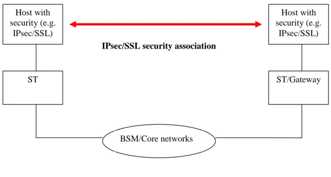
All security is provided between end hosts that implement security technology such as IPsec and SSL (figure 1). This configuration is transparent to BSM.
For example, IPsec in transport mode or TLS/SSL can used here providing data privacy and integrity between clients, and the trust is end-to-end. Users can also identify the security requirements and choose appropriate methods. However, IPsec solution it is not transparent to protocol adaptation and data compression if performed by Performance Enhancing Proxies (PEP) within the BSM networks.
Host with
security (e.g.
IPsec/SSL)
Host with
security (e.g.
IPsec/SSL)
ST
ST/Gateway
IPsec/SSL security association
BSM/Core networks
Figure 1: Security association between end hosts
4.4.2 Gateway-to-Gateway
security
Security is provided only between security gateways (can be collocated with BSM ST or Gateway, figure 2). This scenario is commonly used to build Virtual Private Networks (VPNs).
For example link layer security (such as DVB-RCS) security can be used. In this case it is transparent to requirements such as network compression, protocol, data compression and NAT.
Also IPsec can be used in a user selected IPsec VPN, tunnel mode providing security e.g. over a corporate network. The user/company decides to do this based on a security policy. The main issue here is ensuring the
authentication/repudiation of the STs and the intergrity of the link, which can be provided more efficiently with the link layer security.
This scenario can be transparent to requirements such as network compression, protocol, data compression and NAT if deployed in the right places in BSM networks (using IPsec after compression or TCP PEP near the BSM ST/Gateways).
Host
Host
ST with
BSM
security
BSM network
BSM security association
ST/Gateway
with BSM
security
Figure 2: Security association between BSM STs/Gateways
4.4.3
Combined host and gateway security
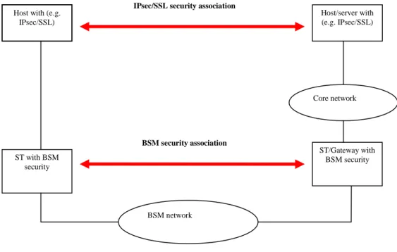
This example extends figure 2 by adding end-to-end security as shown in figure 3. The gateway-to-gateway tunnel provides either authentication or confidentiality or both for all traffic between the gateways. Individual hosts may implement additional IPsec/SSL services.
However, using both technologies could be a potential source of delay and poor performance.
Host with (e.g. IPsec/SSL) Host/server with (e.g. IPsec/SSL) ST with BSM security ST/Gateway with BSM security BSM network BSM security association IPsec/SSL security association
Core network
4.4.4
Remote host to gateway security
This provides support for a remote host that uses the Internet to reach its organization's network (figure 4). Tunnel mode is required between the remote host and the security gateway. If end-to-end security is required, the remote host may use an additional SA to a corresponding host.
The most common deployed configurations are VPNs and remote users. For example, provider selected IPsec VPN, tunnel mode can used here to provide security e.g. over the BSM network. This similar to the end-to-end scenario in that it is not transparent to protocol adaptation and data compression if performed by Performance Enhancing Proxies (PEP) within the BSM networks.
Host with
security (e.g.
IPsec/SSL)
Host
ST
ST/Gateway
with BSM
security
BSM/Core
networks
BSM security association
Figure 4: Security association for remote access
4.5
ITU-T Recommendations - X.805 security architecture
This Recommendation defines a network security architecture for providing end-to-end network security
(see bibliography TS 102 460). This architecture can be applied to various kinds of networks where the end-to-end security is a concern and independently of the network's underlying technology. It defines the general security-related architectural elements that are necessary for providing end-to-end security as shown in figure 5. The objective here is to serve as a foundation for developing the detailed recommendations for the end-to-end network security.
X.805_F4 A cc es s co n tro l Infrastructure security Services security End-user plane Control plane Management plane THREATS VULNERABILITIES 8 Security dimensions ATTACKS Da ta c o n fi d ent ia lit y Co m m u n ic a tio n s e cu ri ty Da ta i n te g r it y A v a ila bi li ty Pr iv ac y A u th en ti ca ti o n N o n -rep u d ia ti o n Destruction Disclosure Corruption Removal Interruption Security layers Applications security Policies & procedures Security program Technology Definition & Planning
Implementation Maintenance
The BSM security architecture definition document applies similar methodology to the X.805 but it is more specific to satellite systems and services. Also it considers gateway-to-gateway security in addition the X.805 end-to-end approach. There are several architectural elements in X.805 (see bibliography TS 102 460) (figure 5) such as security dimensions, security layers, security planes and the analysis of threats and attacks on these elements and the development of a security program. The BSM security architecture document addresses most of these issues with a different approach where the focus is the satellite networks and less emphasis is attached to end-to-end security.
4.6
Summary of security service requirements
• End-to-end security (such as IPsec) and link layer security should work in parallel without obstructing each other.
• Data confidentiality is the major requirement against passive threats (using encryption).
• Optional protection of link layer MAC address.
• BSM terminal authentication (link layer). This will be part of the key management. It will be performed during the initial key exchange and authentication phase.
• For active threats: Source authentication and data integrity are required, using techniques such as message authentication code and digital signatures. Active threats are more difficult to perform and therefore, link data integrity/authentication in BSM network is optional, but still important in environments in which several independent networks share a single transmission resource.
• Decoupling of BSM key management functions from BSM data encryption. This will allow the independent definition of these systems such as the re-use of existing security management systems
(e.g. GDOI RFC 3547 (see bibliography) and GSAKMP RFC 4535 (see bibliography) ) and/or the development of new systems, as required.
In addition here are some general requirements:
• User services support: The security solution should use the same mechanisms for both unicast and multicast services (such as negotiation, authentication, keying and re-keying processes). However, the present document does not address the secure multicast architecture.
• Operational issues: Because of the large satellite coverage, the satellite system may operate over many different countries that may have different security laws (related to authorized encryption algorithms and length of keys). Moreover, the satellite system will be deployed for many years and may operate with different versions of terminal firmware. Therefore the BSM security system should allow a wide range of security parameters during a negotiation phase in order to offer flexibility to operators.
• Compatibility with other service provide or subscriber security functions: Taking into account the role of the different actors (Access Network Operator, Internet Service Provider), it can be possible to have
simultaneously different security schemes. For example, the ISP or a subscriber could use its own security systems above the data link (such as some users intending to deploy IPsec and other not). Therefore the security solution in BSM should not interfere with the one proposed by a Service provider or by subscriber.
• Compatibility with other networking functions: Other networking functions such as NAT (Network Address Translation) or TCP acceleration can be used in a satellite system. The BSM security solution should be compatible with functions such as NAT/NAPT, IPsec, SSL, etc.
• Forward and return channel security: Forward link privacy is essential, however return link security is optional.
• Establishing trust between communication entities: When cryptography is employed to provide protection for data, the issue of trust comes to the foreground. The problem concerns the entities that generate, distribute and manage the cryptographic keys and security policies. This requirement addresses the issues of which entities are to be accorded trust to carry out these functions, the level of trust accorded to them, the source of authority, and other related issues.
Regarding the security technologies described in clause 8, IPsec and link layer security are the major candidates to be used to satisfy the BSM security service requirements.
The major advantage of IPsec is its wide implementation in IP routers and hosts. The decision to use IPsec in transport mode is a decision made by a specific pair of end-hosts. The use in tunnel mode is a choice for the user/network operator. IPsec tunnel mode can be used to provide security over BSM networks. However, there are overheads associated with using IPsec in tunnel mode as a method to protect such links. IPsec tunnel mode also does not provide security services for other network protocols that may be used with ULE (e.g. MPLS, Ethernet Bridging), requiring several methods to be implemented. Another issue, that is important in some deployment scenarios, is the need to protect the identity of end users/Receivers over a broadcast medium; IPsec can not provide this service.
Link layer security is therefore considered an additional security mechanism to IPsec. It provides similar functions to that of IPsec, but in addition provides link confidentiality and optional protection of BSM terminals MAC address. End-to-end security, IPsec and BSM link security can work in parallel: IPsec providing end-to-end security between hosts and link layer providing security over the BSM transmission link. The BSM security manager may interact with both IPsec and the link layer security systems, in order to provide security services in the most efficient way and avoid duplication of security services at various layers if possible.
In hybrid satellite/terrestrial scenarios, where the satellite hop is only one part of the total communication path, then end-to-end security (such as IPsec) is the preferred solution, although satellite link layer can be provided as an additional measure to strengthen the secure BSM service.
5
BSM Security Functional Architecture Requirements
This work is based on BSM services and architectures as defined in IABG final report. ESA project (see bibliography) and (see bibliography TR 101 985). However, there is similar work in the ETSI TISPAN group on security architecture specification in Next Generation Networks (NGN) TR 187 002 (see bibliography). This specification determines the necessary security functionality, describes suitable security functions, components and building blocks for NGN. Several concepts here are common with BSM networks.
This clause describes the BSM security functional building blocks (reference framework) and interactions with non-BSM entities such as COPS, RADIUS, DIAMETER and PEPs.
5.1
Security reference framework
The Reference Framework for BSM security adopts the IETF reference framework and has three broad functional areas: secure data handling, key management and security policy, as shown in figure 6. It incorporates the main entities and functions relating to BSM security. Such security entities can be deployed below or above the SI-SAP (figure 10). The aim of the Reference Framework is to provide some general context around the functional areas, and the
relationships between the functional areas. Some issues span more than one functional area. An example of such a case is the expression of policies concerning BSM keys, which involves both the functional areas of BSM key management and policies.
In the reference Framework diagrams, the singular "boxes" in the framework do not necessarily imply a corresponding singular entity implementing a given function. Rather, a box in the framework should be interpreted loosely as pertaining to a given function related to a functional area. Whether that function is in reality implemented as one or more physical entities is dependent on the particular solution. As an example, the box labelled "Key Server" must be interpreted in broad terms as referring to the functions of key management.
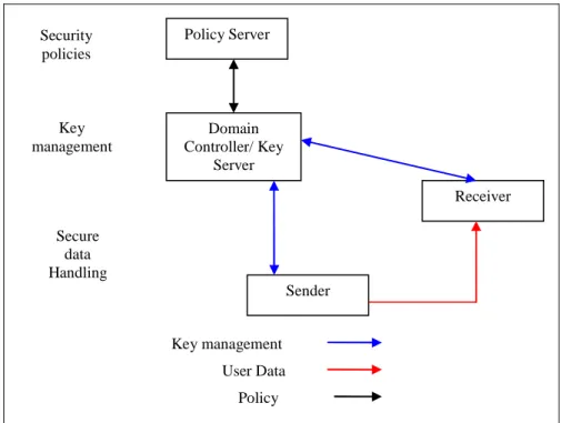
Policy Server Security policies Domain Controller/ Key Server Key management Receiver Sender Secure data Handling Key management User Data Policy
Figure 6: Functional areas for centralized BSM security reference framework
The reference framework can be centralized or distributed. The centralized scenario as shown in figure 6. The boxes are the functional entities and the arrows are the interfaces between them. Standard protocols are needed for the interfaces, which support the unicast/multicast services between the functional entities. There are three sets of functional entities: Domain Controller and Key Server
The Domain Controller and Key Server (DCKS) represent both the entity and functions relating to the issuance and management of cryptographic keys used by a domain (within the BSM network). The DCKS also conducts
user authentication and authorization checks on the candidate members. Sender and Receiver
Both Sender and Receiver must interact with the DCKS entity for the purpose of key management. This includes user and/or terminal (such as STs) authentication/authorization, the obtaining of keying material in accordance with some key management policies, obtaining new keys during key-updates, and obtaining other messages relating to the management of keying material and security parameters. Senders and Receivers may receive much of their policy from the DCKS entities or direct interaction with the Policy Server.
Policy server
The Policy server represents both the entity and functions used to create and manage security policies specific to services or applications using BSM network. The Policy server interacts with the DCKS entity in order to install and manage the security policies related to the sender/receivers and those related to keying material. The interactions between the Policy server and other entities in the reference framework is dependent to a large extent on the security circumstances being addressed by a given policy.
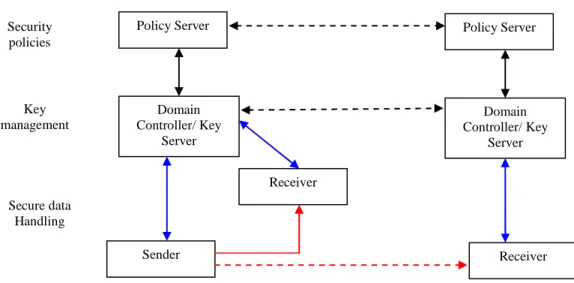
A distributed reference (figure 7) framework is needed for solutions to be scalable for scenarios that span more than one BSM administrative/security domain. An example of an administrative/security domain is a single company VPN using a BSM network. However, BSM gateways might be used to forward data (such as file transfer from a terrestrial ISP) to STs belonging to different VPNs with various security policies and rules.
Policy Server Security policies Domain Controller/ Key Server Key management Receiver Sender Secure data Handling Policy Server Domain Controller/ Key Server Receiver
Figure 7: Functional areas for distributed BSM security reference framework In a distributed design, the DCKS entity interacts with other DCKS entities to achieve scalability in the key
management related services. DCKS entities will require a means of authenticating their peer DCKS entities, a means of authorization, and a means of interacting securely to pass keys and policy. Similarly, Policy servers must interact with each other securely to allow the communication and enforcement of policies across the Internet.
5.1.1
Data handling (privacy and integrity)
Secure data handling covers the security-related treatments of data by the sender and the receiver. In a typical secure session, the data needs to be:
• Encrypted using a key, mainly for access control and possibly also for confidentiality.
• Authenticated, for verifying the source and integrity of the data.
5.1.2 Key
management
This security service describes the functionality of distributing and updating the cryptographic keying material throughout the life of the an active session. Components of this security service may include:
• DCKS to member (Sender or Receiver) notification regarding current keying material (e.g. encryption and authentication keys, auxiliary keys used for security management, keys for source authentication, etc.).
• Updating of current keying material, depending on circumstances and policies.
• Termination of the session in a secure manner.
Key Servers and members may take advantage of a common Public Key Infrastructure (PKI) for increased scalability of authentication and authorization. To allow for an interoperable and secure IP security protocol, this security service may need to specify host abstractions such as a Security Association Database (SAD) and a Security Policy Database (SPD) similar to IPsec. Thus, this security service takes into account the key management requirements for IP.
This security service also describes the functionality of the communication related to key management among different DCKS servers in a distributed design. Key Management appears in both the centralized and distributed designs as shown in figure 7.
5.1.3
Security policy establishment and enforcement
BSM Security Policies must provide the rules for operation for the other elements of the reference framework. Security Policies may be distributed in an ad-hoc fashion in some instances. However, better coordination and higher levels of assurance are achieved if a Policy Controller distributes Security Policies to the BSM members. For example, policy would specify the authorization level necessary in order for an entity to join a session.
The translation of policy rules from one data model to another is much more difficult in a distributed secure environment. This is especially true when a service membership spans multiple administrative domains. Policies specified at a high level with a Policy Management tool must be translated into more precise rules that the available security policy mechanisms can both understand and implement.
Security policy management includes the design of the policy server, the particular policy definitions that will be used for IP services and application-layer security, and the communication protocols between the Policy Server and the Key Server. This security service may be realized using various mechanisms:
• Using a standard policy infrastructure such as a Policy Decision Point and Policy Enforcement Point architecture (RFC 2748 and RFC 3084) (see bibliography).
• Using the key management protocol to transfer the security policy.
• Using other protocols such as Session Initiation Protocol (SIP) to transfer the security policy or even through web services.
At minimum, however, this security service will be realized in a set of policy definitions, such as every session security conditions and actions.
5.1.4
Security association description
A Security Association (SA) is a commonly used term in cryptographic systems. A Security Association usually contains the following attributes:
• Selectors: such as source and destination addresses.
• Properties: such as an Security Parameter Index (SPI) or cookie pair, and identities.
• Cryptographic policy: such as the algorithms, modes, key lifetimes, and key lengths used for authentication or confidentiality.
• keys, such as authentication, encryption and signing keys. The three categories of SAs are:
Registration SA (REG)
A separate unicast SA between the DCKS and each member (senders and receivers). This SA is required for (bi-directional) unicast communications between the DCKS and a member (be it a Sender or Receiver). This SA is established only between the DCKS and a Member. The DCKS entity is charged with access control to the keys, with policy distribution to members (or prospective members), and with security key dissemination to Sender and Receiver members.
The Registration SA is initiated by the member to pull SA information from the DCKS. This is how the member requests to join the secure session, or has its SA keys re-initialized after being disconnected from the network (e.g. when its host computer has been turned off during re-key operations). The SA information pulled down from the DCKS is related to (and used to protect) the rekeying and data two SAs (see below).
However, the requirement of a registration SA does not imply the need of a registration protocol to create that
Registration SA. The registration SA could instead be setup through some manual means, such as distributed on a smart card. Thus, what is important is that a Registration SA exists, and is used to protect the other SAs.
Re-key SA (REKEY)
A single SA between the security manager and members. In some cases, a DCKS needs the ability to "push" new keys during a secure session. This will be satisfied with the Re-key SA.
Data Security SA (DATA)
A data SA between sources and destinations. The Data Security SA protects data between member senders and member receivers. From the perspective of the Receivers, there is at least one data security SA for the member sender.
5.1.5
BSM security functional elements
For data handling, BSM Senders and Receivers can be end users or BSM terminals (ST or Gateways). The data privacy/integrity are preformed using security methods that are agreed upon during the key management messages exchanges and according to the BSM security policy rules.
For the key management function, the DCKS is referred to as the BSM Network manager that is in charge creating and distributing keys to BSM Senders and Receivers. The Security Association categories: REG (registration), REKEY and DATA can be separate or combined depending on the BSM services and security policy rules.
For the BSM security policy, it can be created by the BSM Network manager or by another entity (such as the NCC). Such policy must be distributed to all security entities in BSM, using secure mechanisms such as COPS or the key management protocol itself.
5.2
BSM Generic Protocol Architecture
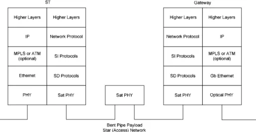
The BSM Generic Protocol Architecture including the security functions (from) is presented in figure 10. It shows the security entities above and below the SI-SAP. The security message flows pass through either SI-U-SAP, SI-C-SAP or SI-M-SAP depending on the nature of these messages. More details are shown in the security cases in clause 6. The BSM architecture document defines the star and mesh configurations:
• Access Network (star configuration) using transparent or processing satellite system. In this configuration the
Internet is accessible in one hop via a gateway. Figure 8 illustrates the protocol stack for the star network and a transparent payload.
Figure 8: Star configuration example of a protocol stack
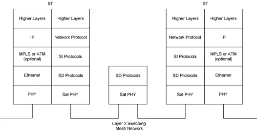
• Mesh Network using peer-to-peer communications between terminals/gateways. When the peer-to-peer
connectivity is provided in one hop (ST to ST), this configuration uses an on-board processing device. This is the configuration most often associated with bridging or switching scenarios (see figure 9). The meshed configuration can also be supported over a transparent payload with double hop: data goes from the source ST to a Gateway and from the Gateway to the destination ST. A special case of the meshed scenario is when the BSM is used for interdomain connectivity, a likely scenario for both multicasting and bridging.
Figure 9: Meshed configuration: example of a protocol stack with Layer 2 switching in the satellite
Regarding security, in both configurations the security processing can be divided into two phases:
• Security establishment: Such as entity authentication and key exchange. This is normally a control plane function in the link layer (e.g. DVB-RCS, similar to out-of-band signalling concept) and user plane in the upper layers (similar to the in-band signalling concept).
• Secure data exchange: Such as using encryption and data integrity. This is normally a user plane function.
SIAF Address Table IP Routing IP Route Determination BSM Security Mgmt
Satellite Link Control (SLC)
Satellite Medium Access Control (SMAC)
Satellite Physical (SPHY)
SDAF
Satellite Data Unit Switching
BSM Address Resolution
BSM Address Resolution
IP Security IPv4 and IPv6
SI-U-SAP SI-C-SAP SI-M-SAP
Segmentation / encapsulation BSM QoS Adaptation BSM Routing Adaptation IP QoS Management IP Packet Forwarding BSM QoS Mgmt BSM Resource Mgmt BSM Security Mgmt BSM Connection CTRL BSM Connection CTRL
5.3
Interactions between security and other non BSM entities
5.3.1
Using COPS for security policy provisioning
The IETF has defined the Common Open Policy Service (COPS) protocol (RFC 2748) (see bibliography) as a scalable protocol that allows policy servers (Policy-PDPs) to communicate policy decisions to network devices. COPS was designed to support multiple types of policy clients.
In BSM network, COPS can used to carry QoS or security information between BSM management entities and satellite terminals (gateways/ST)
RFC 3084 (see bibliography), describes the use of the COPS protocol for support of policy provisioning (COPS-PR). This specification is independent of the type of policy being provisioned (QoS, Security, etc.). The data model assumed in the present document is based on the concept of Policy Information Bases (PIBs) that define the policy data. In order to support a model that includes multiple Policy-PDPs controlling non-overlapping areas of policy on a single Policy Enforcement Point (Policy-PEP), the client-type specified by Policy-PEP to the Policy-PDP is unique for the area of policy being managed. A single client-type for a given area of policy (e.g. security) will be used for all PIBs that exist in that area. The client should treat all the COPS-PR client-types it supports as non-overlapping and independent
namespaces where instances MUST NOT be shared.
5.3.2 Radius/
Diameter
Authentication, Authorization and Accounting (AAA) protocols such as and RADIUS (RFC 2865) (see bibliography) was initially deployed to provide dial-up PPP and terminal server access. This can be achieved using the Remote Authentication Dial-In User Service (RADIUS) protocol.
The RADIUS client is responsible for passing user information to designated RADIUS servers, and then acting on the response which is returned. RADIUS servers are responsible for receiving user connection requests, authenticating the user, and then returning all configuration information necessary for the client to deliver service to the user. A RADIUS server can act as a proxy client to other RADIUS servers or other kinds of authentication servers. To do so, the client creates an "Access-Request" containing such Attributes as the user's name, the user's password, the ID of the client and the Port ID which the user is accessing. When a password is present, it is hidden using a method based on the RSA Message Digest Algorithm MD5.
This protocol is widely implemented and used. Experience has shown that it can suffer degraded performance and lost data when used in large scale systems, in part because it does not include provisions for congestion control. As a result, DIAMETER (RFC 3588) (see bibliography) should be considered as an alternative protocol to RADIUS. IPsec can be used with both RADIUS and DIAMETER. For example in RFC 3162 (see bibliography), RADIUS support for IPsec is not required. However, IPsec support is mandatory in DIAMETER, and TLS support is optional.
In BSM networks, communications between DIAMETER client and server are transparent to BSM security. However if RADIUS is used then either IPsec or link layer security must be used to carry such authentication/authorization
messages.
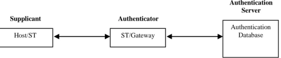
For the purpose of the present document, the RADIUS/ DIAMETER concepts are abstracted. Therefore, three authentication entities are defined below and the authentication process is illustrated in figure 11:
• Supplicant: The client or machine requesting access to the network.
• Authenticator: The second component of the architecture is the access device or gateway, which is typically a switch or an access-point or a hub. The device in an authentication system that physically allows or blocks access to the network.
• Authentication server: This is typically a RADIUS/DIAMETER server or others against which the users will authenticate and from which they can even receive their authorization rules.
Host/ST Authentication Database ST/Gateway Supplicant Authenticator Authentication Server
Figure 11: Host/machine authentication process
5.3.3
Interactions between BSM security and Network Address
Translation (NAT)
Perhaps the most common use of IPsec (RFC 2401) (see bibliography) is in providing Virtual Private Networking (VPN) capabilities. One popular use of VPNs is to provide telecommuter access to the corporate Intranet. Today, Network Address Translations (NATs) as described in (RFC 3022) (see bibliography), are widely deployed in home gateways, as well as in other locations likely to be used by telecommuters, such as hotels. However, IPsec-NAT compatibility issue is a transitional problem and is related to the limited address space in IPv4. In IPv6 will address the address scarcity is not a problem. Therefore, to be useful, an IPsec-NAT compatibility solution MUST be deployable on a shorter time scale than IPv6.Here are some example compatibility issues between IPsec and NAT (3715)
(see bibliography):
• Incompatibility between IPsec AH (RFC 2402) (see bibliography) and NAT. Since the AH header incorporates the IP source and destination addresses in the keyed message integrity check.
• Incompatibility between checksums and NAT. TCP and UDP checksums have a dependency on the IP source and destination addresses through inclusion of the "pseudo-header" in the calculation. As a result, where checksums are calculated and checked upon receipt, they will be invalidated by passage through a NAT or reverse NAT device.
Therefore if IPsec is used in BSM networks then NAT issues should be addressed for remote access,
terminal-to-terminal and end-to-end scenarios. One solution is using the Realm Specific IP (RSIP, RFC 3103, RFC 3104) (see bibliography). This solution will work for only a single NAT and does not work with multiple NATs. A more generic solution is to adopt the IETF recommendations in BSM networks which resolves the compatibility issues, by implementing the following:
• UDP encapsulation of IPSec ESP packets as specified in RFC 3948 (see bibliography).
• IPSec key management and NAT traversal as specified in RFC 3947 (see bibliography).
• IPSec AH mode should not be used.
5.4
Interactions between security and Performance Enhancing
Proxies (PEP)
The Transmission Control Protocol (RFC 0793) (see bibliography) (TCP) is used as the transport layer protocol by many Internet and intranet applications. However, in certain environments, TCP and other higher layer protocol performance is limited by the link characteristics of the environment. Performance Enhancing Proxy (PEP) can perform mitigation techniques (RFC 3135) (see bibliography). A PEP is used to improve the performance of the Internet protocols on network paths where native performance suffers due to characteristics of a link (such as satellite links) or sub network on the path. A large spectrum of PEP devices exists (RFC 3449) (see bibliography), ranging from simple devices (e.g. ACK filtering) to more sophisticated devices (e.g. stateful devices that split a TCP connection into two separate parts).
However there are some security implications for using PEP is satellite environment. The most detrimental negative implication of breaking the end-to-end semantics of a connection is that it disables end-to-end use of IPsec. In general, a user or network administrator must choose between using PEPs and using IPsec. If IPsec is employed end-to-end, PEPs that are implemented on intermediate nodes in the network cannot examine the transport or application headers of IP packets because encryption of IP packets via IPsec's ESP header (in either transport or tunnel mode) renders the TCP header and payload unintelligible to the PEPs. Without being able to examine the transport or application headers, a PEP may not function optimally or at all.
If a PEP implementation is non-transparent to the users and the users trust the PEP in the middle, IPsec can be used separately between each end system and PEP. However, in most cases this is an undesirable or unacceptable alternative as the end systems cannot trust PEPs in general. With a transparent PEP implementation, it is difficult for the end systems to trust the PEP because they may not be aware of its existence. Even if the user is aware of the PEP, setting up acceptable security associations with the PEP while maintaining the PEPs transparent nature is problematic (if not impossible).
There are some steps which can be taken to allow the use of IPsec and PEPs to coexist. If an end user can select the use of IPsec for some traffic and not for other traffic, PEP processing can be applied to the traffic sent without IPsec. Another alternative is to implement IPsec between the two PEPs of a distributed PEP implementation. This at least protects the traffic between the two PEPs. (The issue of trusting the PEPs does not change).
Host
ST with BSM security
BSM network
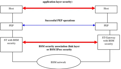
BSM security association (link layer or BSM IPsec security ST/Gateway with BSM security PEP Host PEP
End-t-end security association (e.g. application layer security)
Successful PEP operations
Figure 12: Suitable Security associations for interworking with PEPs In BSM networks and as shown in figure 12, PEPs can be used successfully in the following configurations:
• With Link layer security which operates on the satellite link only (such as DVB-RCS security).
• With IPsec provided that IPsec is used between the BSM ST/Gateway, where IPsec encryption is performed on incoming traffic after the PEP operations and decryption is performed on outgoing traffic before the PEP operations.
Thus the requirement is that security must be implemented in such away that allows PEP entity access to the transport protocol headers (such as TCP). Therefore link and application layer security are transparent to PEPs. If IPsec is used, then PEP operations must be performed outside the IPsec processing as shown in figure 12. IABG final report. ESA project (see bibliography) provides further information about PEPs and security issues over satellites.
5.5
Summary of Security Architecture Requirements
The BSM security architecture must support the following functional requirements:• The BSM security architecture must support a "modular" approach. So that different subsets of security functions can be implemented (not all or nothing).
• Either support security services above SI-SAP (such as IPsec) or below SI-SAP (such as link layer security using DVB-RCS).
• The security services must include data privacy, integrity and BSM source authentication. BSM terminal authentication is optional.
• BSM Network security manager function must be implemented to provide overall control on security procedures and policies.
• The security key management (key agreement and distribution) and data handling (encryption and integrity) functions implementation must insure no negative impact on BSM network performance.
• Capability to implement the range of methods for security methods to allow for difference between encryption laws in various countries.
6
BSM security Functional Architecture Definition
The BSM architecture elements are defined in this clause together with the detailed interactions across the SI-SAP interface.
6.1 Detailed BSM security functional architecture
This clause presents the detailed security system in various architectural cases. These security cases are focused on the positioning of security functions above or below the SI-SAP. For example the security key management and data encryption entities can both be above or below the SI-SAP or one above and one below. All these cases are elaborated in this clause.
In addition, the concept of BSM Security association Identity (SID) is presented. For example, if there is a secure connection between an ST and a Gateway, then SID is the reference number that is used to convey security information between BSM Local and Network security managers such as encryption keys, digital signature methods and security policy exchanges.
If there is only one single BSM Network security manager, then SID will be unique for the whole BSM network. If there are several Network security managers (for example one for each ISP), then SID must be used in conjunction with BSM-ID of the source and destination entities, in order to identify a security association between two BSM entities.
The security cases presented here apply to both BSM star and mesh topologies. For a mesh topology with no On-Board Processor (OBP), STs communicate with each other through a BSM gateway (hub). For a mesh topology with OBP, STs communicate directly with each other without the need for the BSM Gateway (Hub). With respect to the security cases presented here, the star and mesh (no OBP) are the same, where the BSM Network security manager function is likely to be located at the BSM Gateway (Hub). However, for a mesh topology with OBP, the main difference is that BSM Network security manager function can be located at any BSM ST.
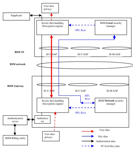
6.1.1
Case 1: IPsec and security entities in BSM
Secure data handling (Encryption engine) SI-C-SAP SI-U-SAP SI-M-SAP BSM Local security manager Supplicant
Secure data handling (Encryption engine) SI-C-SAP SI-U-SAP SI-M-SAP BSM Network security manager Authentication server BSM network User data privacy User data privacy User data Key data Authorisation data BSM Gateway BSM ST
ST local Key data
SID, Keys SID, Keys SID, Keys Authentica tor BSM Billing entity
Figure 13: Case 1 IPsec and BSM security entities
As shown in figure 13, this case illustrates the use of IPsec over BSM network in a security gateway-to-gateway configuration such as VPN over satellites scenario. IPsec protocol operates above the SI-SAP.
Security is provided between a security gateways (that can be co-located with BSM ST or Gateway). The security gateway consists of two functional entities:
Secure data handling entity (privacy/integrity engine): IPsec must operate in tunnel mode.
key management entity: In a star topology, there will a Network security manager for the whole BSM network (co-located with BSM gateway/hub). In addition there is a Local security manager in each ST.
Figure 13 shows all security entities are above SI-SAP. The diagram also shows that the SI-U-SAP (the user interface) ONLY is used to communicate all secure information (user data and key management messages).
The client authentication process (supplicant, authenticator and Authentication server entities) is shown here as well, where IPsec is used to carry authentication information (such as user name and password) between Supplicant and authentication server.
Both the authentication server and the BSM network manager communicate with the BSM NCC regarding security and authorization. These interactions are not shown here in order to simplify the diagram. As described in clause 5.2.4, registration and re-key security association must be established between the BSM Network security manager and Local security managers in each ST. In the case of IPsec, the IETF Internet Key Exchange (IKE) protocol (RFC 4109) (see bibliography) must be used to establish all security associations. This will ensure the mutual authentication between all security entities, establishing the keys used subsequently to secure the user data. Using IKE will also ensure
compatibility between BSM and the general Internet (terrestrial) security systems.
However IPsec for multicast (star topology) is a challenge because IPsec tunnels must be set from the BSM gateways per ST. This is effectively a unicast configuration and the benefits of IP multicast are lost.
Draft-ietf-msec-ipsec-extensions-02.txt is work in progress in defining the extra detail needed for IPsec to work efficiently with multicast. The Security Architecture for the Internet Protocol security architecture document (RFC 4301) describes security services for traffic at the IP layer. That architecture primarily defines services for Internet Protocol (IP) unicast packets, as well as manually configured IP multicast packets. The draft-ietf-msec-ipsec-extensions-02.txt further defines the security services for manually and dynamically keyed IP multicast packets within that Security Architecture.
6.1.2
Case 2: Mixed link layer security entities in BSM (security manager
above SI-SAP and security engine below SI-SAP)
Secure data handling (Encryption engine) SI-C-SAP SI-U-SAP SI-M-SAP BSM Local security manager Host/User Supplicant
Secure data handling (Encryption engine) SI-C-SAP SI-U-SAP SI-M-SAP BSM Network security manager Authentication server BSM network Server
User data (encrypted) Key data Authorisation data BSM Gateway BSM ST Clear text BSM Billing entity
ST local Key data
SID, Keys
SID, Keys
SID, Keys
SID, Keys
Authenticator
Figure 14: Case 2 Mixed link layer BSM security entities
As shown in figure 14, this case illustrates the use of link layer security (below SI-SAP) with the key management (security manager) as an application (above the SI-SAP in a star topology with a centralized security Network manager (can be co-located with the BSM gateway/hub). Typical examples of such system are DVB-RCS with MPE or
Unidirectional Lightweight Encapsulation (ULE) RFC 4326 (see bibliography) IP encapsulation.
Like case 1, the security is provided between security gateways (can be co-located with BSM ST or Gateway). The security gateway consists of two functional entities:
Secure data handling entity (privacy/integrity engine): e.g. is DVB-RCS security which performs data encryption below SI-SAP