UCGE Reports
Number 20400
Department of Geomatics Engineering
Implementation and Evaluation of Interoperable Open
Standards for the Internet of Things
(URL: http://www.geomatics.ucalgary.ca/graduatetheses)
by
Seyyed Mohammad Ali Jazayeri
UNIVERSITY OF CALGARY
Implementation and Evaluation of Interoperable Open Standards for the Internet of Things
By
Seyyed Mohammad Ali Jazayeri
A THESIS
SUBMITTED TO THE FACULTY OF GRADUATE STUDIES IN PARTIAL FULFILMENT OF THE REQUIREMENTS FOR THE
DEGREE OF MASTER OF SCIENCE
DEPARTMENT OF GEOMATICS ENGINEERING CALGARY, ALBERTA
APRIL, 2014
Abstract
Recently, researchers focused on a new use of the Internet called Internet of Things (IoT), in which capable electronic devices can be remotely accessed over the Internet. All around the world, IoT applications are emerging exponentially with various functionalities in order to monitor and control the environment. For example, Wemo switch, Philips Hue light bulb, Ninja Blocks and Air Quality Egg are samples of the existing IoT applications which make environmental dynamics accessible via the Internet. Each application is developed based on the developer’s desire of the device. That means the number of proprietary protocols is growing as the number of IoT devices increases. Moreover, IoT devices are intuitively heterogeneous in terms of the hardware capabilities and communication protocols. Therefore, ensuring interoperability is an important step to integrate various devices together. In this research, we focus on the communication challenges of the IoT objects to make the network suitable for a wide scale of IoT devices. To do this, we implement open standards in different communication layers on a resource constraint IoT object. The standard protocols developed in this research are OGC PUCK over Bluetooth, TinySOS (a lightweight profile of the OGC SOS), SOS over CoAP, and OGC SensorThings API. To the best of our knowledge, these implementations are the world’s first contribution for the IoT objects. Eventually, we benchmark the efficiency of the implemented protocols by a comprehensive performance analysis in terms of memory occupation, request size, response length and response latency. As a result, by hosting the aforementioned open standard protocols on IoT devices, not only the devices become self-describable, self-contained, and interoperable, but also innovative applications can be simply developed by standardized interfaces.
Acknowledgements
There are a number of people without whom this thesis might not have been written, and to whom I am greatly indebted. My sense of gratitude to one and all who, directly or indirectly, have lent their helping hand in this venture.
First, I would like to thank my supervisor, Dr. Steve Liang, for encouraging my research and for giving me the opportunity to pursue my Masters degree in University of Calgary. Your advice on both research as well as on my career have been priceless.
I would also like to thank my committee members, Dr. Mea Wang, Dr. Xin Wang, and Dr. Andrew Hunter. I want to appreciate you for letting my defense be an enjoyable moment, and for your brilliant comments and suggestions.
I also give thanks to the entire research group, the GeoSensorweb Lab, for helping me with my research, and providing invaluable feedbacks. I owe Alec Huang thanks for reviewing my thesis, but more importantly for your academic support during my graduate degree. I give special thanks to Tania Khalafbeigi, Mahdi Oraei, and Reza Malek, who took it upon yourselves to help me in revising my thesis content.
I want to give a special thanks to my family including my parents, my siblings and my grandma. Your love and support have made it possible for me to excel in school and without you, I would not be where I am today. Words cannot express how grateful I am to the sacrifices that you have made on my behalf.
At the end, I wish to dedicate this thesis to the person I love and who has changed my life for the better in every way possible. To Setareh Sajadi, with all the love I have to give. You spent sleepless nights with and were always my support in the moments when there was no one to answer my queries. I will be grateful forever for your love.
Table of Contents
Abstract ... ii
Acknowledgements ... iii
Table of Contents ... iv
List of Tables ... vii
List of Figures and Illustrations ... viii
List of Symbols, Abbreviations and Nomenclature ... xi
CHAPTER ONE: INTRODUCTION ...1
1.1 Background ...1
1.2 Internet of Things ...2
1.3 Existing IoT Applications ...5
1.4 Interoperability ...8
1.5 Problem Definition, Motivation and Solutions ...10
1.6 Objective and Contributions ...13
1.7 Development Platform ...14
1.8 Definition of Terms ...15
1.9 Thesis Organization ...17
CHAPTER TWO: PUCK OVER BLUETOOTH...18
2.1 Introduction ...18 2.2 Related Works ...19 2.3 Architecture ...20 2.3.1 OGC PUCK ...20 2.3.2 Sensor Protocol ...22 2.3.3 System Architecture ...24 2.4 Implementation ...25 2.4.1 Service Layer ...25
2.4.2 Additional Software Components ...26
2.5 Discussion ...27
2.6 Summary ...27
CHAPTER THREE: TINYSOS ...29
3.1 Introduction ...29 3.2 Related Works ...32 3.3 Architecture ...34 3.3.1 TinySOS ...34 3.3.2 System Architecture ...35 3.3.3 Resource Discovery ...37 3.4 Implementation ...39
3.4.1 Tiny Web Server ...39
3.4.2 XPU Algorithms ...41
3.5 Discussion ...44
3.6 Summary ...45
4.1 Introduction ...47
4.2 Related Works ...49
4.3 Architecture ...50
4.3.1 CoAP Specification ...50
4.3.2 Device Architecture ...53
4.3.3 SOS Integration to CoAP ...54
4.4 Implementation ...56
4.4.1 SOS Request to a CoAP Server ...56
4.4.2 CoAP Request to a SOS Server ...57
4.5 Discussion ...57
4.6 Summary ...58
CHAPTER FIVE: OGC SENSORTHINGS API ...59
5.1 Introduction ...59
5.2 Related Works ...60
5.3 Architecture ...62
5.3.1 API Components and Ecosystem ...62
5.3.2 Data Model ...63 5.3.3 System Architecture ...64 5.4 Implementation ...66 5.4.1 Device Registration ...67 5.4.2 Observations Uploading ...69 5.4.3 Actuator Tasking ...69 5.5 Discussion ...72 5.6 Summary ...73
CHAPTER SIX: EVALUATION AND RESULTS ...74
6.1 Introduction ...74 6.2 Performance Evaluation ...75 6.2.1 Memory Occupation ...75 6.2.2 Request Size ...77 6.2.3 Response Length ...78 6.2.4 Response Latency ...81 6.3 Summary ...83
CHAPTER SEVEN: CONCLUSIONS AND FUTURE WORKS ...84
7.1 Introduction ...84
7.2 Conclusions ...85
7.3 Future Works ...87
REFERENCES ...89
APPENDIX A ...99
A.1 Sample requests and responses used in Section 6.2 ...99
A.1.1 Simple Web Server ...99
A.1.4 SOS over CoAP ...102 A.1.5 OGC SensorThings API ...104
List of Tables
Table 2.1 Command set of the OGC PUCK ... 21
Algorithm 3.1 Naive pattern matching ... 42
Algorithm 3.2 Revised pattern matching ... 43
Table 4.1 Mapping SOS operations to CoAP requests ... 56
Table 4.2 CoAP responses to SOS requests... 57
Table 5.1 Device registration procedres ... 67
Table 5.2 Response codes of the response engine ... 71
List of Figures and Illustrations
Figure 1.1 The Internet of Things scheme ... 3
Figure 1.2 Technical overview of the IoT [15] ... 4
Figure 1.3 Existing IoT applications: (a) Wemo switch(http://blessthisstuff.com); (b) Philips Hue light bulb (http://theverge.com); (c) Ninja Blocks (http://ninjablocks.com); (d) Air Quality Egg (http://airqualityegg.wikispaces.com) ... 6
Figure 1.4 Internet protocol graph [28] ... 10
Figure 1.5 The placement of PUCK, TinySOS, and CoAP in the IoT ... 13
Figure 1.6 Netduino Plus mainboard [31]... 15
Figure 2.1 The overall workflow of accessing to the sensor measurements ... 19
Figure 2.2 PUCK memory ... 22
Figure 2.3 Procedures of the sensor protocol... 23
Figure 2.4 The system architecture supporting PUCK protocol ... 24
Figure 2.5 The high level workflow of the service layer ... 26
Figure 3.1 The system architecture supporting TinySOS protocol [30] ... 36
Figure 3.2 Resource discovery process [30] ... 39
Figure 3.3 Code size comparison [30] ... 40
Figure 3.4 The high-level workflow of the XPU [30] ... 41
Figure 3.5 Using a SWE client to access a TinySOS device ... 44
Figure 4.1 High level view of the SOS over CoAP strategy ... 48
Figure 4.2 CoAP message format [55] ... 51
Figure 4.3 CoAP client-server interaction: (a) CON request; (b) NON request [55] ... 52
Figure 4.4 Empty ACK because of response deferral ... 53
Figure 4.5 The device architecture supporting CoAP protocol ... 53
Figure 4.6 The architecture of SOSCoAP Proxy ... 55
Figure 5.2 URI Components ... 63
Figure 5.3 Data Model ... 64
Figure 5.4 The device architecture supporting OGC SensorThings API ... 65
Figure 5.5 An example of registration request... 68
Figure 5.6 An example of IoT service response ... 68
Figure 5.7 Tasking request triggered from user to IoT service ... 70
Figure 5.8 Workflow of the response engine ... 71
Figure 6.1 Different components of our development platform ... 74
Figure 6.2 Request size evaluation for the get observation request ... 78
Figure 6.3 Response size vs. the number of sensor readings ... 79
Figure 6.4 Response size vs. the number of sensor readings (removed the OGC SensorThings trend) ... 80
Figure 6.5 Response latency vs. the number of sensor readings ... 82
Figure 6.6 Response latency vs. the number of sensor readings (removed TinySOS) ... 83
Figure A.1.1 HTTP GET request to the simple web server ... 99
Figure A.1.2 Wireshark screenshot to analyze the requests sent to the simple web service ... 99
Figure A.1.3 GETREADING request and its response to a PUCK-enabled Netduino Plus through Bluetooth ... 100
Figure A.1.4 Statistics of the GETREADING request ... 100
Figure A.1.5 GetObservation request to TinySOS by using 52 North test client tool ... 101
Figure A.1.6 Wireshark screenshot to analyze the requests sent to TinySOS ... 101
Figure A.1.7 GetObservation request to the SOSCoAP proxy ... 102
Figure A.1.8 Get observation request sent to a CoAP server (i.e., Netduino Plus) ... 102
Figure A.1.9 Wireshark screenshot to analyze the requests sent to the CoAP server ... 103
Figure A.1.12 Wireshark screenshot to analyze the request sent to the SensorThings service .. 104 Figure A.1.13 Response of the SensorThings to multiple readings request ... 105 Figure A.1.14 Summarized response of the SensorThings ... 106
List of Symbols, Abbreviations and Nomenclature
Symbol Definition
API Application Programming Interface
CoAP Constraint Application Protocol
CPU Central Processing Unit
EEPROM Electronically Erasable Programmable Read Only Memory
EXI Efficient XML Interchange
GPRS General Packet Radio Service
HTML Hyper Text Markup Language
HTTP Hyper Text Transfer Protocol
IETF Internet Engineering Task Force
IoT Internet of Things
ITU International Telecommunication Union
IP Internet Protocol
JSON JavaScript Object Notation
LAN Local Area Network
MAC Medium Access Control
MTU Maximum Transmission Unit
M2M Machine to Machine
OS Operating System
OData OASIS Open Data Protocol
OGC Open Geospatial Consortium
OWS OGC Web Services
O&M Observation and Measurement
PC Personal Computer
P2P Peer-to-Peer
RAM Random Access Memory
ROM Read Only Memory
RFID Radio Frequency Identification
SBC Single Based Computer
SensorML Sensor Modeling Language
SID Sensor Interface Descriptors
SOS Sensor Observation Service
SPOF Single Point Of Failure
SPS Sensor Planning Service
SSL Secure Socket Layer
SWE Sensor Web Enablement
SWG Standards Working Group
TCP Transmission Control Protocol
TLS Transport Layer Security
UDP User Datagram Protocol
UPnP Universal Plug and Play
URI Uniform Resource Identification
UUID Unique Universal Identification
VGI Volunteered Geographic Information
WSN Wireless Sensor Network
XML Extensible Markup Language
Chapter One: Introduction
1.1Background
The term “Sensor Web” was first used by Kevin Delin in 1997 [1] to describe a wireless sensor network (WSN) architecture where sensors can cooperate as a whole. Nowadays, we are witnessing the increasing number of deployments of WSNs and Sensor Web on the Earth. These networks consist of spatially distributed autonomous sensors, each of which is used to monitor the physical or environmental conditions (e.g., temperature, humidity, sound, motion, etc.) and to cooperatively pass their data through the network to a main location (end user) [2]. WSNs have been involved in many traditional applications, including habitats monitoring systems [3], environment observation systems [4], structure health monitoring systems [5], health applications [6], and fire emergency response systems [7].
Although the traditional monitoring systems (e.g., sensor networks) can provide precise and accurate measurements, the deployment of these systems is usually labour-intensive and challenging [8]. Therefore, a new paradigm called Citizen Sensing or Volunteered Geographic Information (VGI) has been proposed to involve the general public into the monitoring system [9, 10, 11]. With citizens measuring environmental properties voluntarily, scientists are able to observe the environment with a much higher spatial and temporal resolution. A key to realize the above citizen sensing vision is to empower citizens with low-cost and easy-to-use sensor systems. Similar to the fact that the affordable and user-friendly PC democratized computing [12], such cost-effective and easy-to-use sensor systems would be widely used in environmental monitoring.
focused on a new use of the Internet called Internet of Things (IoT), in which capable electronic devices can be remotely accessed over the Internet. Since the IoT is made of different kinds of objects, such device heterogeneity will pose challenges in terms of interoperability. Thus, the goal of this research is to address the interoperability issues of the IoT.
Among the existing Internet-enabled devices, sensor is one of the key enablers in the IoT paradigm [13]. For instance, sensors allow objects to sense the environment around them such as thermometer, water gauges, cameras, etc. Since the IoT and sensors are tightly integrated, the vision of the IoT and the World Wide Sensor Web [14] are similar. One immediate solution to the IoT interoperability challenge can be using the interoperable protocols for the sensor networks. The other solution can be to design a new specific protocol for the Internet of Things.
This chapter gives a brief presentation of the research topic by first introducing the Internet of Things paradigm and the existing progress in the IoT applications. Next, we define interoperability as a research motivation followed by problem definition and solutions. It then states the research objectives and our contributions to overcome the introduced problem. In addition, this chapter mentions our development platform, and a brief definition of the terms used in the next chapters. Lastly, the remaining chapters are outlined.
1.2Internet of Things
The Internet connected services are growing rapidly. A great number of people use the Internet for web surfing, multimedia accessing, sending and receiving emails, playing games, shopping, social networking and many other daily tasks. Consequently, World Wide Web can intuitively be a good candidate to involve citizens into the sensing systems.
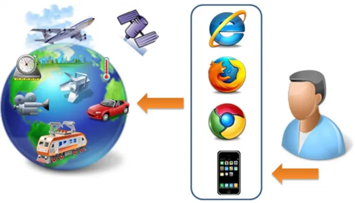
Therefore, the concept of Internet of Things (IoT) emerged as a networking infrastructure to interconnect electronic objects over the medium of the Internet. The prime goal of the IoT is to
capture the observations from sensors, control IoT devices, and finally make those devices easily available through the Internet. As illustrated in Figure 1.1, all electronic devices which are capable of Internet connectivity (e.g., sensors, actuators, machines, and computers) can be visited through the Internet browsers (e.g., web browsers and cell phone applications).
Figure 1.1 The Internet of Things scheme
To technically define IoT, we echo the definition provided by International Telecommunication Union (ITU) [15]: "Internet of Things is a global infrastructure for the information society, enabling advanced services by interconnecting (physical and virtual) things based on existing and evolving interoperable information and communication technologies". Figure 1.2 depicts this concept by mapping the physical world to the digital world across communication networks. According to this technical viewpoint, IoT would certainly affect on different aspects of the potential user’s life and behaviour. For example, assisted living, e-health,
systems are only a few examples of possible application scenarios in which the new paradigm will play a leading role in the near future.
Figure 1.2 Technical overview of the IoT [15]
Referring to the definition provided by ITU, a Thing is also described as a uniquely identifiable instance of the physical world or the information world, which can be integrated into communication networks [15]. In this research, a Thing denotes a physical device in the physical world with the mandatory capabilities of communication and the optional features of sensing, actuation, data capture, data storage and data processing. Bormann et al. [16] worked within IETF1 analyzed and categorized IoT objects into three categories with respect to their communication capabilities: class-0 devices (i.e., impossibly limited devices), class-1 devices (i.e., devices with about 10 Kbytes of RAM and 100 Kbytes of code space), and class-2 devices (i.e., devices with about 50 Kbytes of RAM and 250 Kbytes of code space). Bormann et al. [16] argue that the class-0 devices require extra help to communicate with other devices; the class-1
devices cannot easily communicate with other devices or applications through traditional XML-data representations and protocols (e.g., HTTP and Transport Layer Security (TLS)); and the class-2 devices are able to communicate with the traditional transfer protocols and data encodings. Based on these arguments, we focus on the relatively inexpensive class-1 IoT devices in this research. Thus, this approach allows us to explore the lower bound of the resources that are required for IoT applications. In that way, we ensure that our design choices can deliver an efficient implementation suitable for a broader application domain.
Here, we identify and emphasis on two of the major issues of the Internet of Things. First, since objects in the IoT act independently, each IoT object needs to be self-describable and
self-contained in order to communicate with other objects or sensors. That is, a Thing should be able to describe and advertise both itself and its capabilities, which in general is the metadata of the Thing. Second, since objects are developed to satisfy a particular need, their communication protocols and data encodings are usually different from each other. This heterogeneity
consequently obstructs the communication and cooperation between objects. Besides the two aforementioned issues, there are other issues in the IoT, such as limited power supply, privacy, and security concerns. While these issues are important, we do not address them here as they are out of the scope of this research.
1.3Existing IoT Applications
IoT projects are dramatically growing in different areas, specifically in energy optimization. Ericsson and Cisco IBSG2 predicted there will be 25 billion Internet-connected devices by 2015
and more than 50 billion by 2020 [17, 18]. Some of the available IoT projects recently released to the IoT market are shown in Figure 1.3.
Figure 1.3 Existing IoT applications: (a) Wemo switch(http://blessthisstuff.com); (b) Philips
Hue light bulb (http://theverge.com); (c) Ninja Blocks (http://ninjablocks.com); (d) Air Quality Egg (http://airqualityegg.wikispaces.com)
Traditionally, network peripherals have not been easy to install. Recent standards such as
Universal Serial Bus (USB) and Plug-and-Play3have improved the situation so that devices are
automatically detected and device drivers are automatically installed. Yet, networked devices, such as Internet gateways and networked printers still require manual setup and configuration.
Wemo switch4 (Figure 1.3(a)) lets electronic devices to be remotely turned on/off. It is an IoT application that follows the Universal Plug and Play (UPnP) [19] protocol in its communication. Using UPnP, when a device is plugged in and turned on, it "just works". However, the Wemo application has to be installed on an Android or iOS device, in order to transfer the network settings to the Wemo switch. Furthermore, the Wemo switch cannot be controlled from outside the network it exists (i.e., Internet).
Philips Hue light bulb5 (Figure 1.3(b)) is a wireless light which can display different tones of white light from warm yellow white to vibrant blue white. The Hue light bulb works similarly by means of a Hue router as a bridge between the bulb and the Hue app. Later on, it is possible to talk to the light bulb by Hue bridge across the Internet. Furthermore, the Hue application and Hue bridge are required to support the remote communication to the device.
Ninja Blocks6 (Figure 1.3(c)) are cloud-enabled components including sensors (e.g., temperature, humidity, motion, window and door contact) and actuators (e.g., lights, power sockets) to monitor and control the environment. Ninja Blocks are more accessible than the two previous IoT apps by integrating the Ninja Block to Ninja clouds on the Internet. The connection between the Ninja Block and Ninja clouds is established automatically based on an API which has already hard-coded on the Ninja Blocks. The cloud also provides a web interface for the clients to aggregate sensor data in a repository. However, if a new device is added to the
network, the device needs to follow the Ninja cloud API to be able to interact with the Ninja server.
Air Quality Egg7 (Figure 1.3(d)) is an air quality monitoring system which provides online access to its observations. The egg is composed of a sensing device that measures the air quality in the environment and a gateway that shares the collected data in real-time. The Air Quality Egg immediately uploads the collected data to an open database service named Xively8
(formerly Cosm and before that Pachube). Although Xively provides online access to the sensor-derived data, users can register their egg at the Air Quality Egg portal9 to visualize the data on a map. Similar to the Ninja Blocks, the Air Quality Egg follows the robust API provided by Xively.
Accordingly, IoT is creating innovative applications by assembling the IoT sensing and controlling capabilities from different sources in effective ways. However, IoT service providers are developing their own proprietary software interfaces for their devices. As mentioned above, even these four instances of IoT applications do not apply the same protocol, application, and communication style in data exchange. This means the number of proprietary interfaces is growing as the number of IoT devices increases. Consequently, an effort is required to interconnect various IoT devices with a shared interface to be globally accessed on the Internet.
1.4Interoperability
Towards the first issue mentioned in Section 1.2, devices should somehow provide web services to advertise the devices capabilities and information in the network. For the second issue, the devices need to be interoperable in their communications. Based on the IEEE definition [20],
7 http://airqualityegg.com 8 https://xively.com 9 http://airqualityegg.com/
syntactic interoperability means the ability of interoperation and information exchange in a system; that is, devices should be able to interactively communicate with a common protocol and data format. Beyond the syntactic definition of the IEEE, devices should exhibit semantic interoperability as well. To clarify, semantically interoperable devices can interpret the exchanged data, and generate meaningful result which is understandable by both sides. Although interoperability has a broader scope, we focus on the syntactic and semantic interoperability in this research.
According to Rodriguez et al. [21], Sensor Web and WSNs play an important role in the IoT. In order to provide global interoperability for all IoT devices, we point to the open standard interfaces defined for WSNs. One of the pioneers in the standardization of WSNs is the Open Geospatial Consortium (OGC). OGC has been supporting geospatial interoperability since 1994. Among all OGC standards, the Sensor Web Enablement (SWE) is a suite of standards to enable sensor network interoperability. SWE standards include Observations & Measurements (O&M) [22], Sensor Model Language (SensorML) [23], Sensor Interface Descriptors (SID) [24], Sensor Observation Service (SOS) [25], Sensor Planning Service (SPS) [26], and PUCK protocol [27]. As a result, one possible solution to achieve the interoperable IoT is the development of these OGC open standards on the IoT devices. Therefore, one of the objectives is to implement the suitable SWE standards for IoT devices, and then we can evaluate whether the SWE standards are suitable for IoT devices or not. In addition, as the SWE standards are designed for scientific grade sensor systems rather than for resource-constrained low-cost IoT devices, there might be a need to define a specific standard for the IoT objects.
1.5Problem Definition, Motivation and Solutions
The information communication, including tasking IoT objects and retrieval of spatio-temporal observations from distributed IoT devices, is a key function in the Internet of Things. The traditional interaction models in the Internet are based on the request/response communication style between network entities. The Internet protocol suite is the networking model for the Internet which contains four layers: Application Layer, Transport Layer, Internet Layer, and
Link Layer [28] as depicted in Figure 1.4.
Figure 1.4 Internet protocol graph [28]
Other than the Link Layer which is significantly related to hardware equipments, Internet Protocol (IP) in the Internet Layer, Transmission Control Protocol (TCP) in the Transport Layer and Hyper Text Transfer Protocol (HTTP) in the Application Layer are mostly used to communicate between computers on the World Wide Web. Therefore, a prominent candidate for the IoT would be the WWW protocols that are very scalable, robust, and ubiquitous [30].
However, the existing Internet protocol suite may not be appropriate for the IoT because of the following reasons:
1. Internet access problem: Many IoT devices are not capable of accessing the Internet. This problem occurs because IoT devices do not meet the hardware requirements in order to connect to the Internet or do not have the stable power supply to be continuously connected to the network. Consequently, IoT should be flexible in integrating the Internet protocol with other protocols in order to make those devices available on the Internet. Involving new protocol(s) to the available network infrastructure typically requires new software and hardware requirements (e.g., gateway) to facilitate the seamless integration of those devices with mobile communication networks or Internet. For example, when a Hue light bulb is going to communicate with a client (e.g., a web browser); the Hue bridge needs to be installed on the network.
2. Lack of standard protocol for IoT data representation: HTTP is a foundation of data communication for the World Wide Web to transfer hypertext across the Internet. However, data representation considerably differs from one device to another because there is no standard defining the data representation in the IoT. For example, plain text,
Hypertext Markup Language (HTML), JavaScript Object Notation (JSON), and
Extensible Markup Language (XML) are possible response formats. In order to supply interoperable access between heterogeneous IoT objects, we need to define a standard protocol on top or in parallel of HTTP.
3. Constrained resources of IoT devices: As we already mentioned in Section 1.2, we focus
Therefore, efficient and compressed data encodings in terms of computational resource consumption (e.g., memory, CPU, bandwidth) are required for these devices.
To alleviate the above deficiencies for the existing Internet protocols of the World Wide Web, an alternative standard protocol(s) needs to be considered. The protocol(s) should be effectively compliant with the requirements of IoT participants (i.e., objects, users, applications, networks, gateways, proxies) in order to make the IoT devices interoperable in the network. The selected protocol(s) can encourage people to participate in the IoT by connecting their sensors and actuators to the network. In this case, IoT will provide real-time sensor data streams with a much higher spatial and temporal resolution. Also, end users can remotely command their daily devices by means of web browsers or mobile applications.
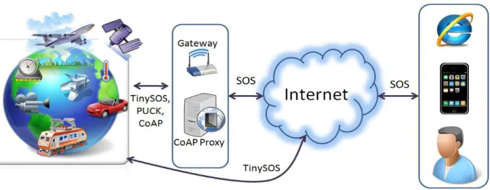
As OGC SOS is a commonly-used web service interface in the Sensor Web, we first connect users to IoT devices based on that protocol. This connection may be established directly through TinySOS protocol [30] which is a compressed implementation of the OGC SOS [25] on the IoT objects. On the other hand, the connection protocol to the device can be modified to OGC PUCK [27] or CoAP [16] which requires intermediary nodes (i.e., proxy, gateway) for protocol conversions (Figure 1.5). The OGC PUCK provides access to the driver code, installation procedures, communication port configuration, and metadata of the device. The CoAP also employs the basic features of HTTP to the constrained network while maintaining a low overhead.
Figure 1.5 The placement of PUCK, TinySOS, and CoAP in the IoT
In addition to using the existing standards for IoT, there is an ongoing effort of defining a standard Web Application Programming Interface (API) for the IoT. This API, namely OGC SensorThings, is built on HTTP protocols and applies the widely-used Representational State Transfer (REST) style to access the system's components.
1.6 Objective and Contributions
The main objective of this research is to address the IoT interoperability issues. To achieve this major goal, we first investigate the current progress on this aspect of the IoT. Then, we implement four standard protocols on a class-1 IoT device including PUCK over Bluetooth, TinySOS, SOS over CoAP, and OGC SensorThings. Finally, we evaluate the four different protocols. To summarize, this thesis makes the following contributions:
We implement the OGC PUCK on a Bluetooth-enabled class-1 IoT object. To make the sensor data available on the Internet, we also integrate the OGC SOS protocol with the PUCK-enabled IoT object.
We implement the heavy-weight OGC SOS and SensorML standards on a resource-constrained sensor (class-1 IoT device). In order to overcome the hardware constraints, we introduce an efficient XML parser algorithm.
To interconnect a CoAP-enabled IoT object with other sensors on the Web, we integrate this protocol to other standards of the WSNs (e.g., OGC SOS) as an interoperable infrastructure for the IoT. Therefore, we implement the commonly-used SOS standard over CoAP on a CoAP proxy which has enough computational resources.
We design a specific RESTful protocol for the Internet of Things called OGC SensorThings API which communicates with IoT objects based on their own defined protocols.
At the end, we complete our contributions by evaluating the performance of the four aforementioned protocols (i.e., PUCK over Bluetooth, TinySOS, SOS over CoAP, and OGC SensorThings) in terms of memory occupation (ROM and RAM), request length, response size and response latency.
The major contribution of this research is to explore the possible approaches to achieve interoperability between class-1 IoT objects. Furthermore, we expect that the direction addressed in this research can be a motive to establish a better infrastructure for the future of IoT.
1.7Development Platform
In this research, we use a sensor compatible Single Board Computer (SBC), namely Netduino Plus. This electronic framework is a low-price (59$) open source hardware platform built by
Secret Labs Company [31]. The board features a 32-bit Atmel microcontroller with 48 MHz speed, 28 Kbytes main memory (i.e., RAM), and 64 Kbytes code storage. In this case, Netduino Plus belongs to the class-1 device category in the framework of Bormann et al. [16].
Furthermore, Netduino Plus supports micro SD memory (up to 4 GB) as a permanent memory to store necessary information such as configuration files, capabilities document, sensor observations, etc. The network connectivity of the board is established by an Ethernet cable, but its mainboard can support other network alternatives (e.g., Wi-Fi, Bluetooth, Zigbee, and GPRS). As shown in Figure 1.6, the mainboard also supports 20 I/O pins (14 digital and 6 analog) where sensors and actuators can be simply attached to. From the software viewpoint, codes developed on this device should be written in C# .Net Micro Framework. Netduino Plus can run the codes directly without any needs for operating systems (OS).
Figure 1.6 Netduino Plus mainboard [31]
1.8 Definition of Terms
For clearer understanding of the terms used in this study, terms and their definitions are as follows:
Actuator- It refers to a transducer that accepts an electrical signal and converts it into a physical
Feature of Interest- This describes a feature (so a representation of a real-world object) that carries the property which is observed. This can be either a domain feature (a.k.a. sampled feature) such as “Mississippi”, or a sampling feature like “water gage X" at Mississippi river. [33]
Gateway- It refers to a device used to connect two different networks, especially a connection to
the Internet [29].
Observation Offering- It groups collection of observations which are somehow similar such as
the observations produced by a specific procedure. [25].
Observed Property- Facet or attribute of an object referenced by a name which is observed by a
procedure [25].
Phenomenon- It is an event in the real world which will be measured. A phenomenon may be a
physical property (such as temperature, length, etc.), a classification (such as species), frequency or count, or an existence indication [34].
Procedure- This involves method, algorithm, instrument, sensor, or system of these which may
be used in making an observation [25].
Proxy server- In computer networks, a proxy server is a server (a computer system or an
application) that acts as an intermediary for requests from clients seeking resources from other servers. A client connects to a proxy server, requesting some services, such as a file, connection, web page, or other resources available from a different server. Then, the proxy server evaluates the request as a way to simplify and control its complexity. Proxies were invented to add structure and encapsulation to distributed systems [35].
Sensor- It is an entity that provides information about an observed property as its output. A
underlying observed property. At the end of the measuring chain, electronic devices produce signals to be processed [25].
Sensor Web Enablement (SWE) - Among the OGC working groups, SWE focuses on
integrating sensors, transducers, and sensor data storages discoverable, accessible and useable via the Web. The OGS SWE standards include: Sensor Observation Service (SOS), Sensor Planning Service (SPS), PUCK, Sensor Model Language (SensorML), and Observations & Measurements (O&M) [36].
1.9Thesis Organization
Chapter 2, 3, 4, and 5 overview PUCK over Bluetooth, TinySOS, SOS over CoAP, and OGC SensorThings API, respectively. Therefore, Chapter 2 to Chapter 5 will independently explain a specific protocol, each of which contains introduction, literature review, architecture, methodology, discussion, and summary sections. Then, Chapter 6 evaluates our implementations by comparing the four protocols in terms of performance analysis. Finally, conclusions and future work are given in Chapter 7.
Chapter Two: PUCK over Bluetooth
2.1Introduction
Among the large scope of OGC standards, we first choose PUCK which is a simple command protocol. The PUCK contains a set of standard commands to access the device memory, read the device metadata, and write data on the memory. The prime purpose of the OGC PUCK is to provide interoperability for devices connected through serial cables or Ethernet. In order to enable sensors to be accessible via wireless connections, we analyze possible radio communication technologies. The choice of the radio highly matters since it influences either energy consumption or software design. Comparing to Zigbee and RF transceiver alternatives applied in WSNs or Sensor Webs, Bluetooth is more popular because it has been widely supported by many daily devices (e.g., cell phone and notebook). In addition, Bluetooth is more energy-efficient in comparison with Wi-Fi. Therefore, we integrate the Bluetooth protocols to the PUCK standard in order to raise the interoperability between various types of sensors and actuators, namely IoT devices.
PUCK standard is efficiently designed to be applied on devices supporting different protocols. It considers two modes: PUCK mode for processing the PUCK commands, and
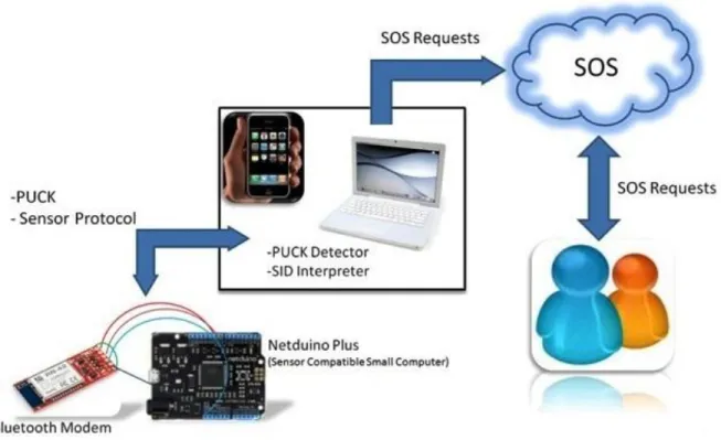
instrument mode for handling instrument-specific operations. Since the PUCK itself has no support for retrieving and publishing the sensor measurements on the Internet, we use other OGC standards, SID and SOS, to provide users the access to the measurements. The workflow is shown in Figure 2.1 and is elaborated in Section 2.4.
Figure 2.1 The overall workflow of accessing to the sensor measurements
To wrap up, the first contribution of this chapter is that we initially enable sensors to be accessible through Bluetooth technology. Then, we integrate Bluetooth protocol and PUCK as an open standard wireless protocol to raise the interoperability of IoT devices.
The remainder of this chapter is organized as follows. In Section 2.2, literature review and related works are stated. Section 2.3 and Section 2.4 present the proposed architecture and implementation, respectively. In Section 2.5, we discuss about the PUCK over Bluetooth idea and its consequent issues. Finally, a summary about this chapter is offered in Section 2.6.
2.2Related Works
Bluetooth has already been utilized in Sensor Web [37] to let sensors upload their readings to a data repository. Leopard et al. [38] achieved this by introducing a tiny Bluetooth stack that allows TinyOS [39] applications to be executed on Bluetooth enabled sensor nodes. While
Leopard et al. [38] focused on the efficient network processing and system architecture design, their research did not consider the interoperability issues between various sensors.
Since the Bluetooth radio range is over a couple of meters [40], the system developed by Leopard et al. [38] does not provide the world wide access to the sensor measurements. To overcome this problem, Ferrari et al. [41] proposed a new architecture for the sensor networks to integrate the Bluetooth-enabled sensors with Internet-connected computers. As a result, these Bluetooth-enabled sensors are essentially connected to the Internet. Although this implementation successfully demonstrated the possibility of combining Bluetooth sensor nodes to the web interfaces, the communication protocol between sensors and computers was proprietary and did not consider the interoperability issues.
Nevertheless, to the best of our knowledge, there is no standard protocol based on the Bluetooth that enables embedded sensors and IoT devices to be connected in an interoperable manner. Therefore, we believe that the integration of Bluetooth and OGC standards for IoT devices that this chapter presents is a pioneer in this field.
2.3Architecture
Here, we briefly introduce the OGC PUCK protocol. Next, we explain the sensor protocol for retrieving sensor observations from the device. Finally, we present the high-level architecture of our proposed system.
2.3.1OGC PUCK
The PUCK protocol provides access to the driver code, installation procedures, communication port configuration, command protocol, and metadata such as OGC SensorML. In general, this standard protocol mainly consists of two parts: PUCK commands, and PUCK memory.
PUCK commands: The protocol has a command-response style in which commands are considered as ASCII strings. Upon successful execution, the device executing PUCK protocol will return the characters: PUCKRDY<CR>. If the PUCK-enabled instrument is unable to execute a command successfully, it will issue a specific error. Table 2.1 shows a summary of the PUCK commands.
Table 2.1 Command set of the OGC PUCK
Command Description
PUCKRM Read from PUCK memory PUCKWM Write to PUCK memory PUCKFM End PUCK write session PUCKEM Erase PUCK memory
PUCKGA Get address of PUCK internal memory pointer PUCKSA Set address of PUCK internal memory pointer PUCKSZ Get the size of PUCK memory
PUCKTY Query PUCK type PUCKVR Get PUCK version string PUCK Null command
PUCKIM Put PUCK into instrument mode PUCKVB Verify baud rate support
PUCK Memory: PUCK memory provides a space for device information, and a memory pointer referring to the memory address that will be read or written by the relevant PUCK commands. Figure 2.2 indicates partitions of the PUCK memory which is mainly divided into two parts: PUCK datasheet and PUCK payload. PUCK datasheet contains a small standard datasheet including a Universally Unique Identifier (UUID), manufacturer ID, PUCK version, header size, and several device related information such as name, version, model ID, and serial number. On the other hand, the optional PUCK payload stores additional information needed to operate the device such as device driver code, SensorML, and so forth.
Figure 2.2 PUCK memory
2.3.2Sensor Protocol
The purpose of sensor protocol is to allow users to simply query sensor capabilities, observations, and presentations of observed features in the instrument mode. As the device we
used in this research does not provide any sensor protocol, we define a protocol based on the concept of OGC SOS [25] to serve the demonstration purpose. Most of the terms used in this part follow the terminology in the OGC SOS. Because of the limited resources in IoT instruments, the command and response formats should be considered as simple as possible. Therefore, unlike the SOS applying XML as the format, this protocol simply defines “separators” (e.g., {#, :, |}) to format requests and responses (Figure 2.3). Similar to the OGC SOS, we define
GETCAPABILITIES operation in order to show the capabilities of the device. The response includes the unique IDs of the sensors attached to the device, the phenomena IDs which are measured by the sensors, and the unit of measurements. Next, the other operation,
GETREADING, can be sent to retrieve sensor readings. Figure 2.3 depicts the procedures of the
2.3.3System Architecture
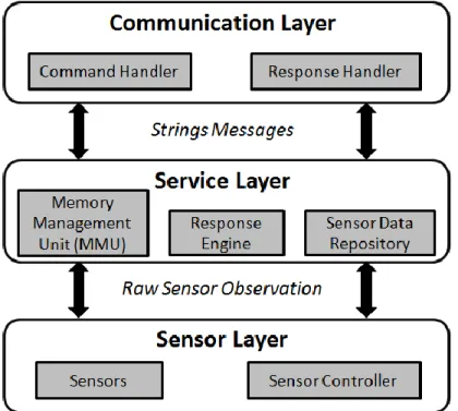
As shown in Figure 2.4, the architecture we proposed for the device follows a layered structure which has three major layers: CommunicationLayer, Service Layer, and Sensor Layer.
Figure 2.4 The system architecture supporting PUCK protocol
Communication Layer: This layer includes the Bluetooth hardware and its protocol. When a request is received, the layer forwards the request string to the service layer for processing. After the service layer finishes processing the request, a response string is returned to the communication layer to send back to the client.
Service Layer: The service layer handles business logic of the system. This layer itself consists of three modules: sensor data repository, response engine, and memory management unit (MMU). More details about the service layer are presented in Section 2.4.
Sensor Layer: The sensor layer consists of the physical sensors and the sensor controller. The sensor controller tasks sensors to collect sensor observations. Next, it sends the retrieved sensor observations to the sensor data repository of the service layer.
2.4Implementation
In this section, we explain the service layer in detail. Then, we introduce the required software components to connect the IoT device to the Internet.
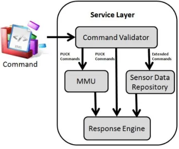
2.4.1Service Layer
In order to parse the commands and compose response messages on the small memory of IoT devices, we propose the response engine. This unit is equipped with a buffering mechanism to handle the large contents. By the way, the maximum memory consumption at any time for reading and writing a document is equal to the buffer size. In our implementation, the buffer size is considered 1 KB which is more than enough for the commands of PUCK and sensor protocol.
The high-level workflow of the service layer is illustrated in Figure 2.5. As the response engine encountered with a carriage return operator, it tries to match the command with the hard-coded commands (i.e., pattern). After pattern matching, the response engine processes the request by retrieving necessary information from the MMU (if the command relates to PUCK memory), or the sensor data repository (if the request contributes to the sensor protocol). Finally, the response engine packages the result in buffers to be sent to the communication layer. The key features in the service layer are the buffering and pattern matching approaches. By these features, we could successively parse and compose large commands (e.g., 100KB) on devices with limited resources (e.g., 25 KB RAM).
Figure 2.5 The high level workflow of the service layer 2.4.2Additional Software Components
As the proposed IoT devices follow the PUCK open standard, users are able to connect to the devices using the PUCK commands. For example, users can develop a PUCK detector
application that establishes Bluetooth connections and sends out PUCK Null command (i.e.,
PUCK<CR>) to discover PUCK-enabled devices. After a successful discovery process, the client can send other PUCK commands to the devices through Bluetooth.
As PUCK provides access to the data in the PUCK memory, PUCK does not support communications in the device protocol. Therefore, we apply another OGC standard, SID, to handle the communications in the device protocol. First, we store a SID file which contains the necessary information about the device protocol, in the PUCK payload for client applications. Then, a client application can use a SID Interpreter [24] to retrieve sensor readings, and upload the observations to an online SOS (Figure 2.1).
2.5Discussion
PUCK over Bluetooth was presented in this chapter as a Bluetooth protocol allowing physical sensors to be interoperable in the Bluetooth established network. Although PUCK protocol was not designed to be hosted on devices with limited resources, we designed and implemented this standard to host on class-1 IoT devices. The developed system has demonstrated that it is feasible to have an interoperable and standard Bluetooth protocol for entire IoT devices. In this case, the Sensor Web can be easily integrated to our daily devices such as mobile phones or notebooks. In spite of popularity of the Bluetooth radio in our daily electronic devices, there are several issues for the aforementioned system.
One issue is that Bluetooth radio has a short frequency range which clearly confines the users to be in proximity to the sensor (e.g., 10m). Although other wireless technologies (e.g., Wi-Fi or RF transceiver) might cover this inconvenience, they lack power conservation, or compatibility with our daily devices.
Moreover, one of the most challenging issues points to the security and privacy concerns. This issue can be solved by considering a passkey on the sensor’s Bluetooth modem which is requested during the pairing process. Also, secure connection can be achieved by leveraging existing standard mechanisms. For example, the current Bluetooth modem uses an encrypted connection to protect the message content's integrity and confidentiality.
2.6Summary
In this chapter, we presented the PUCK over Bluetooth protocol, as a wireless profile of the OGC PUCK for IoT devices. Thereafter, we defined the OGC SOS-like commands to query the capabilities document, and sensor readings. Furthermore, to address the world-wide access to the
sensor readings, we proposed the PUCK detector and SOS service developed on the host, which is able to establish Internet connectivity.
By hosting open standard Bluetooth protocol on the IoT devices, not only the devices become interoperable and easily plugged-and-played, but also the collected observations are accessible via our daily devices as soon as they are measured. In this case, we can easily make sensors available whenever wherever leading to a part of our tomorrow’s daily life.
Chapter Three: TinySOS
3.1Introduction
The basic concept of the IoT is the ubiquitous existence of various things or objects that can communicate and cooperate with each other in order to achieve shared goals [42]. By giving objects the possibility to interact with each other, the IoT is attracting a wide range of applications. For example, Giusto et al. [42] categorized IoT applications into five categories: transportation and logistics, healthcare, smart environments, personal and social, and futuristic applications.
In general, this chapter addresses the issues from the decentralized and heterogeneous
nature of IoT objects and sensors. The main idea is basically inspired by two papers published by Priyantha et al. [43] and Bormann et al. [16]. Priyantha et al. [43] proposed a tiny web service
for sensors and an application-level interface which have three advantages. First, each sensor becomes self-describable and self-contained by providing web interfaces for applications to retrieve sensor's capabilities. Second, some sort of privacy is preserved for device owners by direct connections to their devices. In addition, the sensor deployment and maintenance are easier with interfaces for updating a sensor's metadata. However, in order to achieve the interoperability between sensors and applications, one solution is to use standard-based web service interfaces and widely-used data encodings in information communication. However, Priyantha et al. [43] defined their own ad-hoc interfaces rather than implementing existing standards. On the other hand, Bormann et al. [16] proposed the Constrained Application Protocol (CoAP) as a lightweight transfer protocol for IoT objects. To develop a lightweight protocol, they used User Datagram Protocol (UDP) [28] to simplify the information exchange
which keeps track of packet delivery. In order to enable CoAP with this advantage of TCP, CoAP applies a re-transmission mechanism for lost packets. However, as most web applications are using HTTP, an extra proxy that translates HTTP and CoAP is required for applications to communicate with IoT objects. Chapter 4 thoroughly explains the specification of the CoAP and its contribution to this research.
According to the two above papers, one effective way to make IoT objects self-describable and self-contained is to implement web services on IoT objects. Moreover, the web services and the communication protocols have to be lightweight enough to be executed on objects with limited resources. Both the tiny web service paper [43] and CoAP paper [16] present a concrete idea about how to address the decentralized and heterogeneous issues of IoT and Sensor Web. However, we argue that the only drawback of these two papers is that they do not take advantage of the existing open standards to address the interoperability issues.
The Open Geospatial Consortium (OGC) established Sensor Web Enablement (SWE) as a group of open standards related to sensors, sensor data models, and Sensor Web services [44]. Similar to the W3C standards, the OGC SWE specifications are consensus-based open standards defined by any individual who is willing to participate. In principle, by following the SWE standards, we can achieve interoperability for the Sensor Web. However, the SWE standards are defined under the concept that web services are intermediaries between end-user applications and the sensors, and the SWE web services are based on HTTP and XML data representation. Lightweight Sensor Web services are not in the scope of SWE10. Thus, to the best of our
knowledge, there is no existing work that evaluates the feasibility of constructing a SWE web
10 A new OGC Standards Working Group (SWG) was formed in June 2012 called the Internet of Things REST API
service directly on an object with limited resources. The reason this evaluation is important is that if SWE web services can be hosted on IoT objects, the IoT objects will not only be self-describable and self-contained, but also they will inherit the comprehensive SWE conceptual model directly. In this case, the IoT objects can interoperate with each other as well as the existing OGC SWE applications. Moreover, some sort of privacy might be preserved by removing the gateways in the path between the applications and devices.
Among the SWE specifications, we choose the Sensor Observation Service (SOS)11
which defines a web service interface for accessing sensor observations and metadata [25], to be implemented on a class-1 IoT object. Our implementation of the SOS is termed TinySOS [30] that supports a lightweight profile of OGC SOS suitable for limited resources IoT objects.
Moreover, to address the issue of discovering IoT objects, we implement a sensor registry service that not only allows a sensor to register and advertise itself, but also lets consumers (e.g., other IoT objects, sensors, or end-user applications) to search for available IoT resources.
In summary, this chapter makes the following contributions:
1. We present TinySOS as an open standard Sensor Web service on the IoT devices. With the aim of doing this, TinySOS enables average users to deploy low-cost sensor systems easily.
2. Instead of using the traditional web service container, we develop a tiny web service whose code size is four times smaller than that of the traditional web service container.
3. To parse and compose potential large XML documents on an IoT device, we implement an XML processor unit (XPU) equipped with buffering mechanism to efficiently read and write XML documents. Therefore, the TinySOS allows a highly constrained device to handle very large XML documents.
4. Finally, to address the resource discovery issue, we implement the sensor registry service that acts not only as a catalog service, but also as a proxy to forward requests and responses between clients and TinySOSs with dynamic IP addresses.
The remainder of this chapter is organized as follows. Section 3.2 reviews the OGC SWE and the literature of integrating SWE and IoT. Section 3.3 and Section 3.4 present the proposed architecture and implementation, respectively. This is followed by a discussion about our findings and other issues about the IoT in Section 3.5. Finally, we this chapter provides a summary in Section 3.6.
3.2Related Works
There have been some existing IoT projects applying proprietary protocols, such as Microsoft's HomeOS [45], Xively12
(previously known as Cosm and before that Pachube), MicroStrain's SensorCloud13, and Wovyn14. Many of them provide a web portal for users to manipulate the data
collected by their sensors. We refer to these web portals as the IoT portals. Most of the IoT portals allow users to visualize the time-series data collected by sensors or publish the data with their own Application Programming Interfaces (APIs). However, in this case, IoT objects, that support only one type of proprietary APIs, form a “silo”, and cannot interoperate with objects in other silos. Consequently, the development of various IoT silos obstructs the development of the
12 https://xively.com
13 http://www.sensorcloud.com/ 14 http://www.wovyn.com/
IoT. Therefore, in order to break down these silos and achieve the vision of an open IoT environment, following open standard protocols is necessary.
Sensor Web Enablement (SWE) as an OGC working group defines open standards related to Sensor Web. The prominent standards in the SWE frameworks are Observations & Measurements (O&M) [22], Sensor Model Language (SensorML) [23], Sensor Observation Service (SOS) [25], Sensor Planning Service (SPS) [26] and PUCK Protocol Standard (PUCK) [27]. O&M defines the standard models and XML schema for observations and measurements collected by sensors. The SensorML specification includes the standard models and XML schema for representing the metadata of sensor systems and processes. SOS presents the standard web service interface for requesting, filtering, and retrieving observations and sensor system information. An SOS service is the intermediary between a client and sensor observation repositories. The SPS specification provides the standard web service interface for users to task
sensors to make observations. The PUCK standard which is introduced in Chapter 2 is a low-level protocol to retrieve SensorML documents, sensor driver code, and other information from sensors.
The SOS and SPS are the two SWE specifications defining the standard web service interfaces. For implementing a SWE web service on an IoT object, we choose the SOS in this chapter due to the fact that the SPS service requires customized implementations depending on each sensor's capabilities.
In fact, there have been some initiatives on integrating SWE and IoT. For example, presentations and talks such as “SWE and IoT”15, “Sensor Web Standards and the IoT”16
,
“Bringing IoT to the mass market - what should a standard do?”17, and “Collaborative
development of open standards for expanding GeoWeb to the Internet of Things”18 were given in
workshops and OGC Technical Committee meetings to discuss the possibility of applying SWE standards on the IoT. In addition, a new OGC working group was formed in June 2012 to define open standards for integrating SWE and IoT [46]. Moreover, Broring et al. [47] implemented
SenseBox, which utilizes the O&M standard in their web service API. However, the web service on their SenseBox does not follow SWE standards. Furthermore, Resch et al. [48] did implement SWE standards (including SOS) on an embedded sensing device. However, their sensor hardware has 512 Mbytes RAM and 32 Mbytes flash memory, which even much more powerful than the class-2 device mentioned in Bormann et al. [16]. Therefore, we argue that it is still necessary to evaluate the feasibility of implementing SWE standards on a relatively inexpensive
class-1-like device.
3.3Architecture
In this section, we introduce the lightweight profile of SOS – TinySOS. Next, we present the high-level system architecture of TinySOS for class-1 IoT objects, and finally discuss our proposed sensor registry service for IoT resource discovery.
3.3.1TinySOS
As mentioned earlier, class-1 devices have limited resources. In order to host web services on class-1 devices, the web service needs to be lightweight enough. Therefore, in this
16 “Sensor Web Standards and the IoT,” Scott Fairgrieve, Northrop Grumman, Expanding GeoWeb to IoT workshop
during COM.Geo, 24 May 2011.
17
“Bringing IoT to the Mass Market - What should a standard do?” Ben Pirt, Pachube, IoT Workshop at OGC TC, November 2011.
18 “Collaborative Development of Open Standards for Expanding GeoWeb to the Internet of Things,” George
implementation, we only select the mandatory operations of the SOS (i.e., the core operations) for the TinySOS. There are three mandatory operations in the SOS, namely GetCapabilities, DescribeSensor, and GetObservation.
The GetCapabilities operation provides access to metadata and detailed information about the available capabilities of the service. The GetCapabilities request can be sent either by HTTP GET or POST request type to retrieve the service metadata as an XML file (i.e., the Capabilities document). The XML file contains metadata about this service, such as unique sensor identifiers, logical groupings of sensor observations (i.e., the ObservationOfferings in the SWE terminology), and the URIs of physical phenomena (i.e., the ObservedProperties) that sensors are measuring. Users can use the information in the Capabilities document to retrieve the sensor metadata and the observations with the other two core operations.
The DescribeSensor operation allows users to retrieve sensor metadata with a unique sensor identifier specified in the Capabilities document. If the DescribeSensor request is valid (i.e., the service has sensor matches the unique identifier), the SOS returns the sensor metadata in the SensorML format.
The GetObservation operation provides access to the observations made by the sensors.
Users can use the ObservationOffering and ObservedProperty in the GetObservation request as criteria in querying sensor observations. According to the criteria specified in the request, the SOS returns the sensor observations in the O&M format.
3.3.2System Architecture
As we can see from the previous sub-section, to support the three core operations of SOS, an IoT object needs the functionalities of validating the HTTP request type (i.e., GET, POST), content
functionalities, here we present the proposed system architecture of the TinySOS service. There are three major layers in the TinySOS service (Figure 3.1), including Communication Layer,
Service Layer, and Sensor Layer.
Figure 3.1 The system architecture supporting TinySOS protocol [30]
1) Communication Layer: The communication layer is responsible for managing the HTTP
requests and responses, including the network related protocols and hardware (e.g., Network Interface Card). When a request is received by a TinySOS service, the communication layer forwards the XML request to the service layer for further processing. After the service layer finishes the task, an XML response is returned to the communication layer, and then sent back to the client.
2) Service Layer: The service layer handles the business logic of TinySOS. This layer consists of three modules: XML processor unit (XPU), response engine, and sensor data
of class-1 devices, the TinySOS service needs a new way to parse XML documents. Therefore, unlike the traditional XML parsers that load the whole XML document into memory, we propose the XML processor unit (XPU) which reads and parses XML documents buffer by buffer. The XPU not only extracts the request criteria parameters, but also composes the GetObservation responses. More details about the XPU are presented in Section 3.4. The request criteria extracted by the XPU are forwarded to the response engine. If it is a GetCapabilities request or a DescribeSensor request, the response engine retrieves a predefined XML file (e.g., the Capabilities document and the SensorMLs) from the permanent memory, and forwards it to the communication layer. Otherwise, if the request is a GetObservation operation, the response engine tasks the XPU to compose the GetObservation response according to the criteria, and forwards the response to the communication layer. In addition, as an SOS should have the ability to return the historical observations, the TinySOS stores sensor measurements in a sensor data repository. Depending on the device, the sensor data repository could be located in the main memory (RAM) or the permanent memory (e.g., micro SD card).
3) Sensor Layer:The sensor layer consists of the physical sensors and the sensor controllers. The sensor controllers closely work with sensors. For example, a sensor controller can task sensors to collect sensor observations and send the collected sensor observations to the sensor data repository in the service layer. The sensor controller would play an important role in supporting SPS on IoT objects.
3.3.3Resource Discovery
![Figure 1.2 Technical overview of the IoT [15]](https://thumb-us.123doks.com/thumbv2/123dok_us/335751.2536826/17.918.107.814.221.564/figure-technical-overview-iot.webp)
![Figure 1.6 Netduino Plus mainboard [31]](https://thumb-us.123doks.com/thumbv2/123dok_us/335751.2536826/28.918.295.684.468.747/figure-netduino-plus-mainboard.webp)

![Figure 3.1 The system architecture supporting TinySOS protocol [30]](https://thumb-us.123doks.com/thumbv2/123dok_us/335751.2536826/49.918.246.676.262.645/figure-architecture-supporting-tinysos-protocol.webp)
![Figure 3.3 Code size comparison [30]](https://thumb-us.123doks.com/thumbv2/123dok_us/335751.2536826/53.918.168.755.427.858/figure-code-size-comparison.webp)
