Best Practice Document
Network Management Automation
Produced by the RENATER-led working group on Metropolitan Area Networking
Authors: J. Benoit (Université de Strasbourg/GIP RENATER), S. Boggia (Université de Strasbourg/GIP RENATER), G. Enderle (Université Joseph Fourier/GIP RENATER), A. Mere (GIP RENATER), S. Muyal (GIP RENATER),
© GIP RENATER 2013 © TERENA 2013. All rights reserved. Document No: GN3plus-NA3-T2-R3.5
Version / date: V1.0, 6 December 2013 Original language : French
Original title: “Référentiel et industrialisation de la gestion du réseau” Original version / date: V1.0, 6 December 2013
Contact: [email protected]
RENATER bears responsibility for the content of this document. The work has been carried out by a RENATER-led working group on metropolitan network as part of a joint-venture project within the HE sector in France.
Parts of the report may be freely copied, unaltered, provided that the original source is acknowledged and copyright preserved.
Table of Contents
Executive Summary 1
1 Components required for network management 2
1.1 Network information system 2
1.1.1 Equipment inventory 2
1.1.2 Configuration management tool 3
1.1.3 Communication between management tools 6
1.2 Management networks 7
1.2.1 IN-BAND management network 8
1.2.2 OUT-OF-BAND management network 8
1.3 Access control tools 10
1.4 Network monitoring and measurement tools 10
1.5 Summary 12
2 Equipment life cycle and day-to-day operation 14
2.1 Deploying equipment 15
2.1.1 Purchase of equipment 15
2.1.2 Receiving and storing the equipment 15
2.1.3 Naming scheme 15
2.1.4 DNS declarations and access control 16
2.1.5 Configuration and provisioning 17
2.1.6 Labelling 17
2.1.7 Deployment 18
2.1.8 Integration into Network monitoring and logging system 18
2.2 Decomissionning an equipment 18
2.3 Replacement of an equipment in case of failure 19
2.4 Day-to-day operation 19
2.4.1 Standard configuration changes 19
2.4.2 Equipment maintenance and replacement stock 22
3 Conclusion 24
Table of Figures
Figure 1.1: Example of a configuration file web form 5 Figure 1.2: Configuration generator using CSV file and parameter template 5 Figure 1.3: Example of an automatic configuration using an Inventory tool 7 Figure 1.4: An Out-of-Band network established in parallel to the user network 9 Figure 1.5: Example of two network monitoring templates 11 Figure 2.1: Pre-production steps: DNS configuration and access control 17 Figure 2.2: Example 1 – the proprietary tool Avaya Enterprise Manager 20 Figure 2.3: Example 2 – the free tool: Netmagis and the Topo module 21
Table of Tables
Table 1.1: Comparison of CSV files with an inventory database 3 Table 1.2: In-band management network: advantages and disadvantages 8 Table 1.3: Out-of-band management network: advantages and disadvantages 9
Table 1.4: Summary of tools arranged by function 13
Executive Summary
This document describes a process, based on a network information system, to bring as much automation as possible to the operation of a set of network equipment.
In term of tools, there are two ways to implement network management solutions:
A single platform that integrates a large number of functions, but which is not necessarily suitable for all requirements and may be difficult to configure. These are often proprietary tools supplied by equipment manufacturers.
A large number of different small tools that are easily adaptable. Each tool has a precise function. The tools interact with one another in different ways (scripts, API, etc.).
In the single platform approach, for many years, proprietary tools have been provided by equipment vendors (e.g. Cisco Prime, HP IMC, Juniper Junos Space, etc.). Most of the time, these tools only support the products of the vendors. Some software vendors specialised in network management solutions are selling tools capable of managing multi-vendors environments.
The approach favoured here does not rely on a single tool. Instead it involves assembling software components that all rely on a central reference data store.
In the first section, the different basic components that allow a network to be managed are briefly described, followed by a list of the most important tools, with the pros and cons of each tool and the situations in which their use is appropriate.
In the second section, we will demonstrate the integration of these tools into a consistent set of actions for automating network operations. The second section will primarily cover the network equipment’s “life cycle” management. The interactions between the tools is detailed, together with the benefits they bring in simplifying repetitive and error-prone tasks (which are precisely the ones generating network configuration errors).
1
Components required for network
management
In this section, we will cover the four points that form an effective way to manage a network: A network information system.
Management networks. Access control tools.
Network monitoring and measurement tools.
1.1
Network information system
1.1.1
Equipment inventory
The first important point involves placing the inventory of the equipments in a single reference data store. This reference data store is accessible to and can be changed by all administrators.
The reference data provides the following information about each equipment: The location of an equipment.
The hardware composition (cards, interfaces, etc.). The software version.
Maintenance information (contracts, operations, etc.).
Status of the equipment: in production, in stock, defective, etc.
Depending on time/money avaiblable and the number of items of equipment to manage, the reference data can take various forms, two of which are shown below:
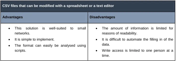
CSV files that can be modified with a spreadsheet or a text editor
Advantages Disadvantages
This solution is well-suited to small networks.
It is simple to implement.
The format can easily be analysed using scripts.
The amount of information is limited for reasons of readability.
It is difficult to automate the filling in of the data.
Write access is limited to one person at a time.
An inventory database (e.g. GLPI, OCS Inventory)
Advantages Disadvantages
These are dedicated equipment inventory tools.
Equipment attributes (serial numbers, MAC addresses, port numbers, etc.) are discovered automatically.
The information is readable.
Complex searches can be made via database queries or with web apps.
Reading from and writing to the database can be easily automated, sometimes via APIs.
Write access is possible for several users at the same time.
The cost of maintaining the software and the data quality is high.
Table 1.1: Comparison of CSV files with an inventory database
1.1.2
Configuration management tool
Keeping track of configuration changes
To supplement the reference data, it is essential to keep track of configuration changes of the network equipments. Logging the changes offers several advantages:
Backing-up configurations after each change allows a configuration to be restored in a previous state very quickly when there is a parameter error or equipment crash,
Changes are traced: it is possible to determine who made a change, when and why it was made. This is especially useful when the operation of the network (NOC) is outsourced,
Corollary: analysing changes allows you to understand malfunctions following one or more configuration errors.
There are multi-vendor configuration management tools such as RANCID [Rancid], an open source program which is fairly easy to implement.
Proprietary solutions also exist, such as the SolarWinds® software suite [SolarWinds], which includes tools to save and manage configurations.
Initial generation of configurations
It is essential to distinguish between the equipement initial configuration, before it is put into production, and the configuration of the equipment during its operation. Configuration deployment is described in the section about the equipment life cycle management (2.).
For equipment deployed on a large scale, such as access switches, it is important to create a standard configuration template. Configurations are then generated automatically based on this template. The use of an initial configuration template has the following advantages:
it reduces configuration errors, as only the parameters change, the configuration is consistent on all equipment,
it is a “bootstrap” process, which enables remote management automation: the templates includes many things related to managing the equipement, such as SSH access configuration, authentication parameters, SNMP agent configuration, log server configuration, etc.
Several methods are possible:
First method: developing your own configuration file generation tools, based on templates.
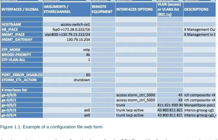
It is possible to organise the template parameters in a CSV file, or to develop a web form containing both the general parameters of an equipment and the configuration of each of its interfaces.
An example is shown below of a CSV that allows a configuration file to be prepared for an equipment to be deployed.
Figure 1.1: Example of a configuration file web form
A script can just generate the configuration by reading the CSV file and feeding the parameter values to the configuration template.
Figure 1.2: Configuration generator using CSV file and parameter template
Vendor-provided software is a complete solution, offering more and more features. They do not require any internal development, but its integration in a multi-vendor environment is difficult, if not impossible.
Checking configuration files integrity
Once the configurations are set up, it is crucial to regularly check that the configuration is consistent with the information system. These verifications can be performed with internally developed tools.
Examples of checks to perform:
Does the equipment exist in the reference data store?
Is a VLAN configured on an interface instantiated on the equipment? Are the VLANs configured on the equipment globally provisioned?
Are network management protocols (SNMP communities, log server)s correctly configured, etc.
The configurations can be analysed after each configuration back-up performed by the configuration management tool (e.g. RANCID).
1.1.3
Communication between management tools
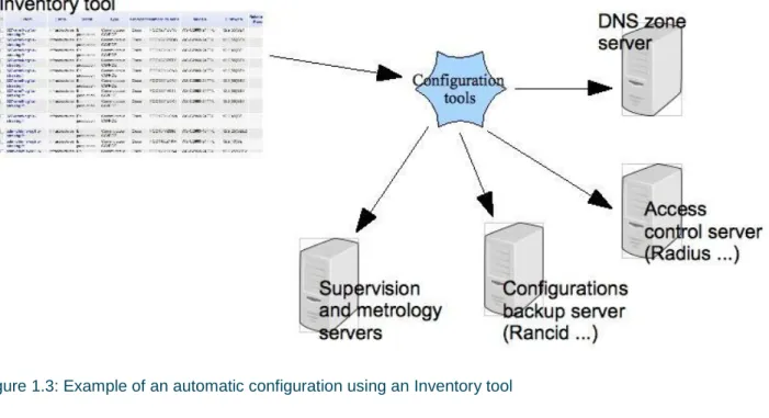
Network administration tools can be configured automatically based on the system inventory. This can be done with APIs or with other tools (either existing tools, such as open source tools or tools that must be developed). For example:
Registering the equipment name in the DNS, associated with its address (whether it’s an internal management address or a public IP addresses).
Configuring the access control to the equipment (Radiusauthentication [Radius]).
Configuring logging: this should be activated only when an item of equipment is put into production (the equipment operational status in the inventory must be polled).
Integrating the equipment into network monitoring and measurement (the same condition applies here: the operational status in the inventory must be “in production”).
Figure 1.3: Example of an automatic configuration using an Inventory tool
It is relatively easy to write the interfaces, provided network administrators can write a few scripts. The scripts are usually relatively simple:
SQL queries or web app tools to extract data from the inventory database.
Generating configuration files from templates (configuration of Radius, Rancid, etc.). Calling configuration APIs (Network monitoring, DNS, etc.).
For example, the Centreon [Centreon]network monitoring solution provides CLAPI [CLAPI], an API that enables network equipment to be integrated into the network monitoring via simple command lines. This solution can easily be used in a script.
Open source tools also exist. Those tools will integrate the network equipments into network management tools, like Nagios [Nagios] or Centreon [Centreon], fetching their name, adresse, SNMP community etc. from inventory databases such as GLPI. Overmon [Overmon] is such a tool.
Another example is the management of software versions on the equipment. A request in the inventory or configuration log collects the system version currently running on the equipment. If the version is lower than the one in production, a script plans and performs the update of the system outside of working hours.
1.2
Management networks
Management access to network equipment can be performed in two different ways: in-band and out-of-band. The opportunity to set up one method or the other depends on several criteria such as the criticality of the equipment, the physical accessibility of the site and the cost. Often, both methods are used on the same
network. The choice of access method has an impact on management automation. This impact is described below for each method.
1.2.1
IN-BAND management network
In-Band management enables access to the equipment configuration interfaces via the standard user network (SSH, Web interface). This is the most appropriate method for collecting information or making (standard) configuration changes, for which there is no risk of loss of management access to the equipment.
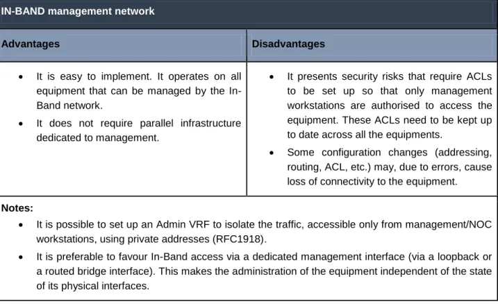
IN-BAND management network
Advantages Disadvantages
It is easy to implement. It operates on all equipment that can be managed by the In-Band network.
It does not require parallel infrastructure dedicated to management.
It presents security risks that require ACLs to be set up so that only management workstations are authorised to access the equipment. These ACLs need to be kept up to date across all the equipments.
Some configuration changes (addressing, routing, ACL, etc.) may, due to errors, cause loss of connectivity to the equipment. Notes:
It is possible to set up an Admin VRF to isolate the traffic, accessible only from management/NOC workstations, using private addresses (RFC1918).
It is preferable to favour In-Band access via a dedicated management interface (via a loopback or a routed bridge interface). This makes the administration of the equipment independent of the state of its physical interfaces.
Table 1.2: In-band management network: advantages and disadvantages
1.2.2
OUT-OF-BAND management network
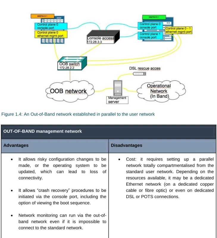
Figure 1.4: An Out-of-Band network established in parallel to the user network
OUT-OF-BAND management network
Advantages Disadvantages
It allows risky configuration changes to be made, or the operating system to be updated, which can lead to loss of connectivity.
It allows “crash recovery” procedures to be initiated via the console port, including the option of viewing the boot sequence.
Network monitoring can run via the out-of-band network even if it is impossible to connect to the standard network.
Cost: it requires setting up a parallel network totally compartmentalised from the standard user network. Depending on the resources available, it may be a dedicated Ethernet network (on a dedicated copper cable or fibre optic) or even on dedicated DSL or POTS connections.
Table 1.3: Out-of-band management network: advantages and disadvantages
The document “Campus Best Practice Network Monitoring and Management Recommendation” [Netmon_Mgmt_BP] contains more information about the Out-of-Band network.
1.3
Access control tools
Access control allows administrators to perform operations on the equipment with their own IDs, which ensures that the connections can be traced in the authentication logs. It also allows user rights management (read-only privileges, read-write privileges, restrictions to run only some commands) to be centralised.
The main reasons for providing access control are:
to simplify configuration. You don’t need to manage a user database on each item of equipment: only one administrator account is needed on the equipment itself. The other user accounts are centralised in the access control server.
to help with diagnostics. If network malfunctions are caused by a configuration change, it is possible to know who accessed the equipment and when, as the authentication logs makes the connections traceable,
to make administrators more responsible, given their actions are monitored.
Centralisation of authentication makes access to the equipment more vulnerable. It is therefore vital to ensure that the access control platform is made secure and reliable, through the deployment of several access control servers, and also keep a local administrator account on the equipment, just in case the access control server is down.
RADIUS [Radius] is the most common access control protocol currently in use. It is the standard protocol with many different implementations, wether commercial or open source, including Free Radius.
TACACS/TACACS+ [TACACS+] is another AAA protocol (Authentication, Authorisation, Accounting). In contrast to Radius, which logs only connections, TACACS allows each command entered on a network equipment to be checked against user permissions and logged in real time. Although the protocol was written by Cisco, it is also available on other vendor’s equipment.
In a highly varied multi-vendor environment, it is recommended to use RADIUS, which is the most common and most widely available protocol.
1.4
Network monitoring and measurement tools
Generic templates: for supervising a function: switch, router, network equipment.
Specific templates: a brand and a specific equipment reference (Cisco C2960G, Juniper MX480 etc.).
For a given network equipment, a generic template can be used, for example the “switch” template, supplemented by a specific template associated with the equipment type.
For example, for the generic “network equipment” template, basic network connectivity is monitored at least for the management interface (Ping, SNMP). This test indicates whether the equipment is still reachable and is therefore remotely manageable. Though the test can be done in-band, it is nonetheless advisable to test the connectivity of the console or Ethernet management interfaces by connecting an interface of the Network monitoring workstation on the Out-of-Band network.
In a specific template, characteristics that are unique to a specific equipment model are taken into account (architecture, availability of information, proprietary MIBs, etc.):
environmental parameters: temperature, power supply, fan, etc.,
performance parameters: CPU, buffers and memory consumption on the equipment components.
In the inventory, the equipment is identified as a “switch” and its brand and part/model number are also present. Based on this informations in the inventory, all the matching templates can be applied.
Thus, network monitoring can be performed automatically by applying templates specific to each type of equipment.
The diagram below shows an example of the application of two network monitoring templates to a network equipment integrated into the network monitoring platform. The first “generic” template will be applied to all network equipment. The second, specific template is only for a Juniper MX480 equipment.
In addition to the application of specific and generic network monitoring templates, additional generic templates can be created for each of the equipment network interface. In this way, the status and statistics of the network interfaces are monitored automatically:
Status (UP/DOWN). Unicast traffic. Broadcast traffic. Error counters.
This implies that a list of all available network interfaces on the equipment is known. This can be based on the inventory, which discovers the equipment interfaces, or on knowledge of the equipment (number of interfaces associated with the equipment type/model, eg. a 24- or 48-port Ethernet switch).
If you want to provide the list of interfaces to be monitored, you could add an attribute to the inventory. Another approach involves placing a comment in the interface description in the equipment configuration. The comment contains a reference to a measurement point (an unique string of character identifying the point). This information will be collected by the configuration management tool and passed on to the inventory. The existence of the measurement point triggers the monitoring of the interface in the networking monitoring tool. Example of interface description with the unique measurement point reference between <...>:
description "interco <M233.local.peer>"
1.5
Summary
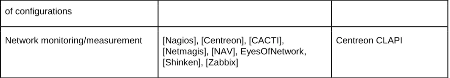
The table below provides a summary of the tools arranged by function. Proprietary network equipment software suites are not covered (we advise you to consult the vendor).
Function Tool API/protocols
Inventory tools GLPI, Fusion Inventory, OCS Inventory GLPI Web Services
IPAM (IP address Management): addresse assignment, DNS records
of configurations
Network monitoring/measurement [Nagios], [Centreon], [CACTI], [Netmagis], [NAV], EyesOfNetwork, [Shinken], [Zabbix]
Centreon CLAPI
2
Equipment life cycle and day-to-day
operation
For optimal operation, the network equipment must be subject to “life cycle” management, which includes the following stages:
Deployment.
Replacement due to failure or developments. Configuration changes.
Decomissionning.
These actions often involve repetitive operations. It is recommanded to automate as many recurrent tasks as possible, such as changing its configuration, or integrating or modifying an equipment in the information system. The life cycle is closely linked to the inventory and must reference the status of each equipment. The status of an equipement can be:
In stock: not deployed; available in stock.
In pre-production: in the process of being configured or deployed on site. In production.
Defective.
Stopped:due to maintenance or changes to network architecture. Removed:decomissioned, end of life cycle.
2.1
Deploying equipment
2.1.1
Purchase of equipment
Following a procedure can help choosing the equipment most suited to your needs.The following aspects need to be taken into consideration:
Type of equipment: router, switch.
Function: backbone, aggregation, access. Critical nature: failure tolerance.
Performance expected. Budget.
The chosen equipment model must meet all the requirements. Supporting only a few models of equipment greatly facilitate management (reduced stock of spare parts, choice of equipment, etc.) and operational aspects (technical competence, simpler configuration, etc.).
2.1.2
Receiving and storing the equipment
The first stage, as soon as the equipment is delivered to you, is to include it in the inventory database:
Entering the serial numbers: it is recommended to automate this process with a barcode scanner. The equipment data is then immediately included in the inventory.
Entering the status into the inventory: in stock or in pre-production if the equipment is to be used immediately.
2.1.3
Naming scheme
The name given to an equipment is particularly important. The name should give an idea of its location and function, and must also be easy to remember. It should suggest something specific.
Thus, a good compromise must be found between quantity of information you want to appear in the name and how easy it is to remember.
It is therefore appropriate to avoid over-long names based on complex naming scheme, those that are difficult to remember, to pronounce or to type on a keyboard. These kinds of names can be a real pain when you need to connect to the equipment in an emergency.
P (Provider) core network equipment CORE (Core) core network switch/router
PE (Provider Edge) provider edge equipment linking sites/buildings
AG (Aggregate) switch/aggregation router for building sites or technical rooms CE (Customer Edge) equipment at the entrance to a building
SW Switch
AS (Access Switch) switch connecting workstations AP (Access point) Wi-Fi access point
A suggested equipment naming scheme is shown below, using the following syntax:
<building or town>-<technical room>-<type of equipment><order number>
Examples:
1st switch located in building 42, technical room (containing the wiring closet) on the 4th floor. bat42-tr04-sw1
2nd core network aggregation router located in Strasbourg. For important (highly visible) core network equipment, it is not necessarily required to specify the room. Its location is generally known as the network administrators routinely connect to the equipment.
sxb-core2
2.1.4
DNS declarations and access control
Before moving on to equipment configuration, one or more (if the access is Out-Of-Band) management addresses must be assigned to it.
The equipment can then move to pre-production. Its name and address are recorded into the DNS and access control is configured. It is of course advisable to perform these tasks automatically using scripts, in order to avoid configuration errors.
Figure 2.1: Pre-production steps: DNS configuration and access control
For routers, adding all interfaces with their associated IP addresses in the DNS is recommended. This will improve visibility when network diagnostics are performed with the traceroute command, for example.
For example: for the gigabitEthernet-1/2/0 interface of the sxb-core2 equipment, the IP associated with this interface is declared as follows:
sxb-core2-ge-1-2-0.provider.example.net
2.1.5
Configuration and provisioning
Depending on the number of equipment items that you manage and if their role is critical or not, the initial configuration can be automated in different ways:
Complete: for equipment deployed on a large scale. The basic parameters are entered into the inventory; configuration templates then allow the configuration to be generated and uploaded to the equipment. The changes carried out afterwards are simple and standard (configuration of an access interface, etc.) and can also be automated.
Partial: for equipment deployed occasionally or with very specific configurations, such as core network equipment, a basic configuration template corresponding to the model deployed is uploaded to the equipment. More complex configuration elements are then added manually.
It is recommended to create a dedicated room or space for the configuration of the equipment. This allow the following possibility:
You can connect the console port to a terminal server, enabling the person who configures the equipment to do so remotely, in a quiet environment,
You can connect the equipment to the Out-of-Band management network, whether through the equipment management Ethernet interface, or, temporarily, through one of its regular network ports, in order to allow the program generating the configurations to upload them to the equipment,
You can connect the equipment to the In-Band management network through one of its regular network ports. This makes it possible to verify, once it has been configured, that the equipment is reachable In-Band, before deploying it in the field.
2.1.6
Labelling
A label must display the name of the equipment as recorded in the DNS in order to know how to connect to it, for example while doing on-site maintenance of the equipment.
If the equipment has an inventory number, it is important that it appears on the label. This allows inventory errors to be avoided when a broken equipment is replaced by another with the same name.
The inventory number is also very useful with stack-type virtual equipment. Although the “hostname” is the same for each member of a stack, they can nonetheless be differentiated by their inventory number.
Finally, for chassis-type equipment, it is recommended to label each card by its inventory number.
2.1.7
Deployment
The equipment is now configured. It has one or more management addresses entered in the DNS. Access control is configured to allow administrators to connect to it.
The equipment is ready to be deployed on site, Its inventory status can be changed to inproduction.
2.1.8
Integration into Network monitoring and logging system
When the equipment status in the inventory moves to in production, this automatically triggers: its integration into the network monitoring system,
its integration into the configuration backup and tracking system.
Deployment is then complete.
2.2
Decomissionning an equipment
Among the possible statuses for an equipment in the inventory, the status “removed” indicates that the equipment is no longer in operation.
2.3
Replacement of an equipment in case of failure
When an equipment experiences a failure, its status in the inventory must be changed to “defective”. Network monitoring is then automatically suspended until the equipment is replaced.
Once the defective equipment has been replaced, the inventory status of the new equipment returns to in production, and takes the IP address and name of the equipment it replaced.
Network monitoring then resumes.
Note: in order to replace an equipment, a maintenance contract or spare stock is recommended. Section 2.4.2 discusses this issue in more detail.
The procedure for replacing a defective equipment with the same model is based on the inventory and the configuration backup system. It includes the following stages:
Taking a replacement equipment from stock or one delivered by your MRO (Maintenance Repair and Overhaul) provider.
Applying the initial configuration with the same parameters (management IP address, etc.) as the failed equipment.
Applying the last known configuration of the failed equipment; the configuration is recovered from the configuration backup system.
When an equipment is to be replaced with a different model, first the decommissioning of the old equipment, then the deployment of the new equipment procedures must be followed.
2.4
Day-to-day operation
2.4.1
Standard configuration changes
Depending on the number of equipment items to be changed, the complexity of the change and the criticality of the equipment, the configuration of the equipment in production can be performed in different ways:
Manual: when the configuration of the equipment changes very little or only in a very specific way, as with core network equipment for example,
Automated: based on a template for standard changes (always identical and very frequent).
Verification after the fact: operators make manual configuration changes to the equipment. Then, a program checks that the configuration is consistent, using the configuration collected by the configuration backup and tracking tool,
A priori generation: configuration elements are generated in a centralised manner, based on parameters and a template, then deployed onto the equipment. It is possible to delegate the configuration management of certain equipment to third-party administrators.
A compromise must be reached between the time taken to develop the templates and the frequency with which they are used.
For example, the most common changes to access equipment are: The activation of an interface.
The addition and deletion of a VLAN. The modification of QoS rules.
The application of an Access-Control List (ACL).
For the generation and upload of configuration elements, the following can be envisaged:
Either in-house development, using RANCID to upload the configurations or even EXPECT scripts [Expect].
The use of manufacturer solutions (e.g. Avaya/Edm).
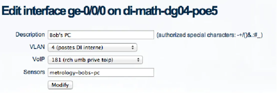
Figure 2.3: Example 2 – the free tool: Netmagis and the Topo module
The configuration parameters above are applied to the interface according to the templates below. The following example uses IOS Cisco Catalyst.
Given the following variables:
%1$s: interface name
%2$s: interface description
%3$s: user VLAN
%4$s: telephony VLAN
Reseting the interface :
interface %1$s no switchport
switchport voice VLAN none switchport
no srr-queue bandwidth share 10 60 10 20 no srr-queue bandwidth shape 10 0 0 0 no service-policy input TOIP-QOS no storm-control broadcast level no storm-control action trap no spanning-tree guard root
Applying workstation-specific configurations :
interface %1$s description %2$s switchport mode access switchport access VLAN %2$s spanning-tree portfast
storm-control broadcast level pps 500 400 storm-control action trap
spanning-tree guard root
Applying telephony-specific configurations : interface %1$s
srr-queue bandwidth share 10 60 10 20 srr-queue bandwidth shape 10 0 0 0 service-policy input TOIP-QOS
2.4.2
Equipment maintenance and replacement stock
The availability of a replacement solution for defective equipment is an essential aspect of network management. Several strategies can thus be implemented, depending on the location and criticality of the equipment.
For critical equipment, such as core equipment, you must minimise the impact of an equipment failure. There are two approaches:
Availability of H+4 maintenance
Advantages Disadvantages
No need to purchase spare equipment. No need to maintain equipment on each site
(e.g. in the context of a remote site).
Sometimes difficult to persuade maintenance service providers to comply with the 4 hour deadline.
High cost.
Availability of replacement equipment, identical to the equipment in production, and of D+1 maintenance (or D+4 depending on the type of equipment)
Advantages Disadvantages
The operations team remains in charge of the replacement (sometimes producing faster results).
Allows the length of the interruption to be reduced.
Requires the purchase of additional equipment.
Requires this equipment to be taken care of (system and configuration updates).
Sometimes requires replacement equipment on remote critical sites.
For example, a maintenance contract offering replacement of equipment within four hours is recommended for critical equipment, if the network covers extensive geographical areas (at a national level). This avoids having to maintain several stocks of spare parts across the country.
A maintenance contract with replacement of equipment within 4-5 days, whatever its type, may be more than sufficient when the network covers limited geographical areas which have spares in stock.
3
Conclusion
Automating the management of network equipment remains a complex and significant undertaking. Nevertheless, the result is worth the effort involved. The upfront investment, which can be only or almost only in terms of HR (or both if you opt for a manufacturer solution), may seem intimidating, but you will improve your efficiency and save time. In each of the best practices presented, we have attempted to offer a range of solutions, thus allowing you to find a solution that is appropriate for your environment. It’s now down to you to make the best of it!
References
[GLP] http://www.glpi-project.org/ [OCS_Inventory] http://www.ocsinventory-ng.org/ [Rancid] http://shrubbery.net/rancid [SolarWinds] http://www.solarwinds.com/ [Radius] http://freeradius.org/ [Centreon] http://www.centreon.com/ [CLAP] https://forge.centreon.com/projects/centreon-clapi [Nagios] http://www.nagios.org/ [Overmon] https://github.com/highfeeling [Netmon_Mgmt_BP] http://www.terena.org/activities/campus-bp/pdf/gn3-na3-t4-abpd101.pdf [TACACS+] http://www.shrubbery.net/tac_plus/ [IPPlan] http://iptrack.sourceforge.net/ [Netdot] https://osl.uoregon.edu/redmine/projects/netdot [Netmagis] http://netmagis.org/ [Cacti] http://www.cacti.net/ [NAV] https://nav.uninett.no/ [Shinken] http://www.shinken-monitoring.org/ [Zabbix] http://www.zabbix.com/ [Expect] http://expect.sourceforge.net