Abstract—Many real-world optimization problems involve multiple conflicting objectives and the use of evolutionary algorithms to solve the problems has attracted much attention recently. This paper investigates the application of multi-objective optimization technique for the design of a Thyristor Controlled Series Compensator (TCSC)-based controller to enhance the performance of a power system. The design objective is to improve both rotor angle stability and system voltage profile. A Genetic Algorithm (GA) based solution technique is applied to generate a Pareto set of global optimal solutions to the given multi-objective optimisation problem. Further, a fuzzy-based membership value assignment method is employed to choose the best compromise solution from the obtained Pareto solution set. Simulation results are presented to show the effectiveness and robustness of the proposed approach.
Keywords—Multi-objective Optimisation, Thyristor Controlled Series Compensator, Power System Stability, Genetic Algorithm, Pareto Solution Set, Fuzzy Ranking.
I. INTRODUCTION
OWER system oscillations and system voltage profile are the two important criteria which define the performance of a power system subjected to a disturbance [1]. There has been much research interest in developing new control methodologies for increasing the performance of the power system. Recent development of power electronics introduces the use of Flexible AC Transmission Systems (FACTS) controllers in power systems. Thyristor Controlled Series Compensator (TCSC) is one of the important members of FACTS family that is increasingly applied with long transmission lines by the utilities in modern power systems [2-8]. The majority of the control methodologies presented in literature concerns improvement of only one type of stability
S. Panda is working as a Professor in the Department of Electrical and Electronics Engineering, NIST, Berhampur, Orissa, India, Pin: 761008. (e-mail: [email protected] ).
S. Swain is working as an Assistant Professor in the Electrical Engineering Department, School of Technology, KIIT University, Bhubaneswar, Orissa, India (e mail:[email protected]).
A.K.Baliarsingh is a Research Scholar in the Electrical Engineering Department, School of Technology, KIIT University, Bhubaneswar, Orissa, India (e-mail:[email protected]).
A. K. Mohanty is an Ex-Professor in N. I. T. Rourkela. now working as a Professor in Electrical Engg. Deptt. at KIIT UNIVERSITY Bhubaneswar
C. Ardil is with National Academy of Aviation, AZ1045, Baku, Azerbaijan, Bina, 25th km, NAA (e-mail: [email protected]).
performance; either improving the oscillatory stability performance (reflected in the deviation in generator speed) or the system voltage profile and minimization of a single objective function is employed to get the desired performance. Multi-objective genetic algorithm approach has been applied to design a TCSC controller [9], where the three objectives are closely related and the voltage deviations are not taken into account. Further, the procedure to obtain the best compromise solution from the obtained Pareto set is not addressed. Obviously, the main purpose of design of any controller is to enable it to improve both oscillatory stability and system voltage profile. Design of such kind of controller is inherently a multi-objective optimisation problem.
There are two general approaches to multiple objective optimisations. One approach to solve multi-objective optimisation problems is by combining the multiple objectives into a scalar cost function, ultimately making the problem single-objective prior to optimisation. However, in practice, it can be very difficult to precisely and accurately select these weights as small perturbations in the weights can lead to very different solutions. Further, if the final solution found cannot be accepted as a good compromise, new runs of the optimiser on modified objective function using different weights may be needed, until a suitable solution is found. These methods also have the disadvantage of requiring new runs of the optimiser every time the preferences or weights of the objectives in the multi-objective function change [10]. The second general approach is to determine an entire Pareto optimal solution set or a representative subset. Pareto optimal solution sets are often preferred to single solutions because they can be practical when considering real-life problems, since the final solution of the decision maker is always a trade-off between crucial parameters [11].
The main motivation for using Genetic Algorithm (GA) to solve multi-objective optimisation problems is because GAs deal simultaneously with a set of possible solutions (the so-called population) which allows the user to find several members of the Pareto optimal set in a single run of the algorithm, instead of having to perform a series of separate runs as in the case of the traditional mathematical programming techniques. The Pareto optimal solutions are ones within the search space whose corresponding objective vector components cannot be improved simultaneously. Additionally, GAs are less susceptible to the shape or continuity of the Pareto front as they can easily deal with
Multi-objective Optimization with Fuzzy Based
Ranking for TCSC Supplementary Controller to
Improve Rotor Angle and Voltage Stability
S. Panda, S. C. Swain, A. K. Baliarsingh, A. K. Mohanty and C. Ardildiscontinuous and concave Pareto fronts, whereas these two issues are known problems with mathematical programming [12].
In this paper, the design problem of a TCSC is formulated as a objective optimisation problem. GA based multi-objective optimisation method is adapted for generating Pareto solutions in designing a TCSC-based controller. The design objective is to improve the oscillatory stability and system voltage profile of a power system following a disturbance. Further a fuzzy based membership function value assignment method is employed to choose the best compromise solution from the obtained Pareto set. Simulation results are presented at various loading conditions to show the effectiveness and robustness of the proposed approach.
The reminder of the paper is organized in five major sections. Power system modeling with the proposed TCSC-based supplementary damping controller is presented in Section II. The proposed design approach and the objective function are presented in section III. In Section IV, an overview of multi-objective optimization gas been presented. The results are presented and discussed in Section V. Finally, in Section VI conclusions are given.
II. MODELING THE POWER SYSTEM WITH TCSC
The single-machine infinite-bus (SMIB) power system installed with a TCSC, shown in Figure 1 is considered in this study. In the figure, XT and XL represent the reactance of the transformer and the transmission line respectively; VT and VB are the generator terminal and infinite bus voltage respectively.
TCSC is one of the most important and best known FACTS devices, which has been in use for many years to increase line power transfer as well as to enhance system stability. Basically, a TCSC consists of three main components: capacitor bank C, bypass inductor L and bidirectional thyristors SCR1 and SCR2. The firing angles of the thyristors are controlled to adjust the TCSC reactance in accordance with a system control algorithm, normally in response to some system parameter variations. According to the variation of the thyristor firing angle or conduction angle, this process can be modeled as a fast switch between corresponding reactance offered to the power system.
1 T 2 T TCSC X T V C X XL B V P X T X C L Generator bus Infinite
Fig. 1 Single machine infinite bus power system with TCSC
A. Non-Linear Equations
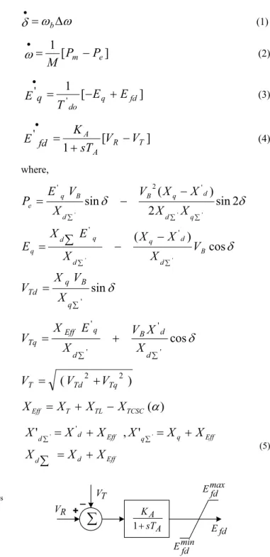
The non-linear differential equations of the SMIB system with TCSC are derived by neglecting the resistances of all components of the system (generator, transformer and transmission lines) and the transients of the transmission lines and transformer. The non-linear differential equations are [13]:
Z
Z
G
x b'
(1)]
[
1
e mP
P
M
xZ
(2)]
[
1
' ' fd q doE
E
T
E
q x (3)]
[
1
' T R A AV
V
sT
K
E
fd x (4) where,G
G
sin
2
2
)
(
sin
' ' ' ' 2 ' ¦ ¦ ¦ q d d q B d B q eX
X
X
X
V
X
V
E
P
G
cos
)
(
' ' ' ' B d d q d q d qV
X
X
X
X
E
X
E
¦ ¦¦
G
sin
' ¦ q B q TdX
V
X
V
G
cos
' ' ' ' ¦ ¦ d d B d q Eff TqX
X
V
X
E
X
V
)
(
Td2 Tq2 TV
V
V
)
(
D
TCSC TL T EffX
X
X
X
Eff d d Eff q q Eff d dX
X
X
X
X
X
X
X
X
¦
¦ ¦',
'
''
' (5) +_¦
T V R V max fd E min fd E fd E A A sT K 1The simplified IEEE Type-ST1A excitation system is considered in this work. The diagram of the IEEE Type-ST1A excitation system is shown in Fig. 2. The inputs to the excitation system are the terminal voltage VT and reference
voltage VR. The gain and time constants of the excitation
system are represented by KA and TA respectively.
B. Linearized Equations
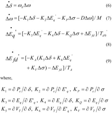
In the design of electromechanical mode damping stabilizer, a linearized incremental model around an operating point is usually employed. The Phillips-Heffron model of the power system with FACTS devices is obtained by linearizing the set of equations (1) – (5) around an operating condition of the power system. The linearized expressions are as follows:
Z
Z
G
'
'
x b (6)M
D
K
E
K
K
q P]
/
[
1G
2 'V
Z
Z
'
'
'
'
'
x (7) ' 0 4 ' 3]
/
[
'
d fd Q qK
K
E
T
E
K
q
E
'
'
'
'
'
xV
G
(8) A fd V q AT
E
K
E
K
K
K
fd
E
/
]
)
(
[
'
' 6 5'
'
'
'
'
xV
G
(9) where,V
G
w
w
w
w
w
w
P
eK
P
eE
qK
PP
eK
1,
2'
,
V
G
w
w
w
w
w
w
E
qE
qK
E
qK
QE
qK
3'
,
4,
V
G
w
w
w
w
w
w
V
TK
V
TE
qK
VV
TK
5,
6'
,
The modified Phillips-Heffron model of the single-machine infinite-bus (SMIB) power system with TCSC-based damping controller is obtained using linearized equations (6)-(9) as shown in Fig. 3. Z ' 'G m P ' + + _ _ _ _ _ _ fd E ' ' Eq ' GTCSC(s) V ' ¦ ¦ ¦ _ _ + 1 K s 0 Z 2 K 4 K 5 K 6 K S V ' D Ms 1 do ' sT K3 1 A A sT K 1 V K Q K P K
Fig. 3 Modified Phillips-Heffron model of SMIB with TCSC-based supplementary damping controller
III. THEPROPOSED APPROACH
A. Structure of Proposed TCSC-based Supplementary Damping Controller
The commonly used lead–lag structure is chosen in this study as TCSC-based supplementary damping controller as shown in Fig. 4. The structure consists of a gain block; a signal washout block and two-stage phase compensation block. The phase compensation block provides the appropriate phase-lead characteristics to compensate for the phase lag between input and the output signals. The signal washout block serves as a high-pass filter which allows signals associated with oscillations in input signal to pass unchanged. Without it steady changes in input would modify the output.
WT WT sT sT 1 2 1 1 1 sT sT 4 3
1
1
sT
sT
T KZ
'
Gain Block Washout Block Two stage lead-lag Block Input Output ) s ( GTCSCV
'
Fig. 4. Structure of the proposed TCSC-based supplementary damping controller
The damping torque contributed by the TCSC can be considered to be in to two parts. The first part KP, which is referred as the direct damping torque, is directly applied to the electromechanical oscillation loop of the generator. The second part KQ and KV, named as the indirect damping torque, applies through the field channel of the generator. The damping torque contributed by TCSC controller to the electromechanical oscillation loop of the generator is:
Z
Z
Z
'
#
'
'
T
DT
D 0K
PK
TK
D (10)The transfer functions of the TCSC controller is:
y
sT
sT
sT
sT
sT
sT
K
u
wT wT T TCSC¸¸
¹
·
¨¨
©
§
¸¸
¹
·
¨¨
©
§
¸¸
¹
·
¨¨
©
§
4 3 2 11
1
1
1
1
(11)Where, uTCSCis the output signal of TCSC controller and y is the input signal. The input signal of the proposed TCSC-based controller is the speed deviation 'Z and the output is the change in conduction angle 'V . During steady state conditions 'V = 0 and so the effective reactance XEff is given by: XEff XT XTL XTCSC(D0). During dynamic conditions the series compensation is modulated for damping system oscillations. The effective reactance in dynamic conditions is given by:XEff XT XTL XTCSC(D), where
V V
V 0' and V 2(SD), D0 and V0 being initial value of firing and conduction angle respectively.
From the viewpoint of the washout function the value of washout time constant is not critical in lead-lag structured
controllers and may be in the range 1 to 20 seconds [1]. In the present study, washout time constant of TWT 10 s is used. The
controller gains KT ; and the time constants T1,T2,T3 and T4
are to be determined.
B. Objective Function
It is worth mentioning that the TCSC controller is designed to damp power system oscillations and improve the system voltage profile after a disturbance. A multi-objective function based on ¨Ȧ and ¨VT is used as an objective function in the present study. The objective can be formulated as the minimisation of function F given by:
F
1,
F
2F
(12) Where,³ '
1 0 1|
|
.
.
tdt
t
F
Z
(13) and³ '
1 0 2|
|
.
.
t Tt
dt
V
F
(14)In the above equations,
|
'
Z
|
and|
'
V
T|
denote the absolute values of rotor speed and terminal voltage deviations following a disturbance and t1 is the time range of the simulation. For the objective function calculation, the time-domain simulation of the power system model is carried out for the simulation period.C. Optimization Problem
In this study, it is aimed to minimize the proposed objective functions F. The problem constraints are the TCSC Controller parameter bounds. Therefore, the design problem can be formulated as the following optimization problem:
Minimize F (15) Subject to max min T T T
K
K
K
d
d
(16) max 1 1 min 1T
T
T
d
d
(17) max 2 2 min 2T
T
T
d
d
(18) max 3 3 min 3T
T
T
d
d
(19) max 4 4 min 4T
T
T
d
d
(20)The proposed approach employs genetic algorithm to solve this optimization problem and search for optimal set of the TCSC Controller parameters.
IV. MULTI-OBJECTIVEOPTIMIZATION
A. Multi-objective optimization
A multi-objective optimization problem (MOP) differs from a single-objective optimization problem because it contains
several objectives that require optimization. In case of single objective optimization problems, the best single design solution is the goal. But for multi-objective problems, with several and possibly conflicting objectives, there is usually no single optimal solution. Therefore, the decision maker is required to select a solution from a finite set by making compromises. A suitable solution should provide for acceptable performance over all objectives.
A general formulation of a MOP consists of a number of objectives with a number of inequality and equality constraints. Mathematically, the problem can be written as [14]: minimise/maximise fi(x) for i =1, 2,…,n. (21) Subject to constraints: gj(x) 0 j = 1, 2, …, J hk(x) 0 k = 1, 2,…, K Where fi(x) = { f1(x),…fn(x)}
n= number of objectives or criteria to be optimized x= {x1, …, xp} is a vector of decision variables
p= number of decision variables
There are two approaches to solve the MOP. One approach is the classical weighted-sum approach where the objective function is formulated as a weighted sum of the objectives. But the problem lies in the correct selection of the weights or utility functions to characterise the decision-makers preferences. In order to solve this problem, the second approach called Pareto-optimal solution can be adapted. The MOPs usually have no unique or perfect solution, but a set of non-dominated, alternative solutions, known as the Pareto-optimal set. Assuming a minimisation problem, dominance is defined as follows:
A vector u = (u1,….,un) is said to dominate v = ( v1,…..,vn) if and only if u is partially less than v ( u p< v),
i
{1,…,n}, uid
vi
i
{1,…,n}; ui < vi (21)A solution xu
U is said to be Pareto-optimal if and only if there is no xv
Ufor which v = f(xv) = (v1,…,vn) dominatesu = f(xu) = ( u1,…,un).
B. Pareto-optimal solutions
Pareto-optimal solutions are also called efficient, non-dominated, and non-inferior solutions. The corresponding objective vectors are simply called non-dominated. The set of all non-dominated vectors is known as the non-dominated set, or the trade-off surface, of the problem. A Pareto optimal set is a set of solutions that are non-dominated with respect to each other. While moving from one Pareto solution to another, there is always a certain amount of sacrifice in one objective to achieve a certain amount of gain in the other. The elements in the Pareto set has the property that it is impossible to further reduce any of the objective functions, without increasing, at least, one of the other objective functions.
Pareto-optimal solutions are also called efficient, non-dominated, and non-inferior solutions. The corresponding objective vectors are simply called non-dominated. The set of all non-dominated vectors is known as the non-dominated set, or the trade-off surface, of the problem. A Pareto optimal set is a set of solutions that are non-dominated with respect to each other. While moving from one Pareto solution to another, there is always a certain amount of sacrifice in one objective to achieve a certain amount of gain in the other. The elements in the Pareto set has the property that it is impossible to further reduce any of the objective functions, without increasing, at least, one of the other objective functions.
C. GA method for generating Pareto solutions
The ability to handle complex problems, involving features such as discontinuities, multimodality, disjoint feasible spaces and noisy function evaluations reinforces the potential effectiveness of GA in optimisation problems. Although, the conventional GA is also suited for some kinds of multi-objective optimisation problems, it is still difficult to solve those multi-objective optimisation problems in which the individual objective functions are in the conflict condition.
Start
Initialize population and Pareto optimal set
Time-domain simulation of power system model
Objective function evaluation
Obtain Pareto solution set
Pareto size > max. size ?
Gen. > max. Gen. ? Apply GA opterators
(selection, crossover and mutation)
Reduce Pareto optimal set size
Stop Gen. = 0
Gen. = Gen. +1 Yes
No
Yes
No
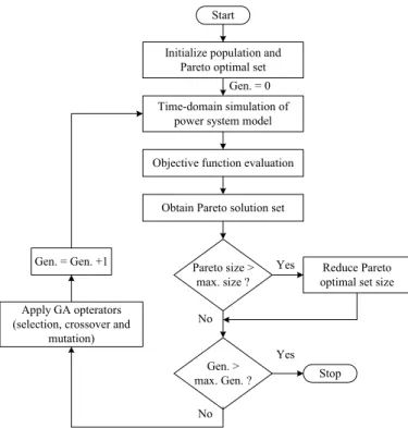
Fig. 5 Flowchart of the multi-objective genetic algorithm optimization algorithm to generate Pareto solutions
Being a population based approach; GA is well suited to solve MOPs. A generic single-objective GA can be easily modified to find a set of multiple non-dominated solutions in a single run. The ability of GA to simultaneously search different regions of a solution space makes it possible to find a diverse set of solutions for difficult problems with non-convex, discontinuous, and multi-modal solutions spaces. The
crossover operator of GA exploits structures of good solutions with respect to different objectives to create new non-dominated solutions in unexplored parts of the Pareto front. In addition, most multi-objective GA does not require the user to prioritise, scale, or weigh objectives. Therefore, GA has been the most popular heuristic approach to multi-objective design and optimization problems.
Pareto-based fitness assignment was first proposed by Goldberg [15], the idea being to assign equal probability of reproduction to all non-dominated individuals in the population. The method consisted of assigning rank 1 to the non-dominated individuals and removing them from contention, then finding a new set of non-dominated individuals, ranked 2, and so forth. In the present study, before finding the Pareto-optimal individuals for the current generation, the Pareto-optimal individuals from the previous generation are added. The computational flow chart of the proposed multi-objective optimization algorithm is shown in Fig. 5.
V. RESULTS AND DISCUSSIONS
A. Application of Genetic Algorithm
The objective function given by equation (12) is evaluated by simulating the system dynamic model considering a 10 % step increase in mechanical power input (¨Pm) at t = 1.0 sec. Optimization is terminated by the prespecified number of generations. While applying GA, a number of parameters are required to be specified. An appropriate choice of the parameters affects the speed of convergence of the algorithm. Table I shows the specified parameters for the GA algorithm. One more important factor that affects the optimal solution more or less is the range for unknowns.
TABLEI PARAMETERS USED IN MULTI-OBJECTIVE GENETIC ALGORITHM
Parameter Value/Type
Maximum generations 100
Population size 50
Mutation rate 0.01
Selection operator Pareto-optimal sorting
Recombination operator Blending
Type of selection Pareto optimal selection
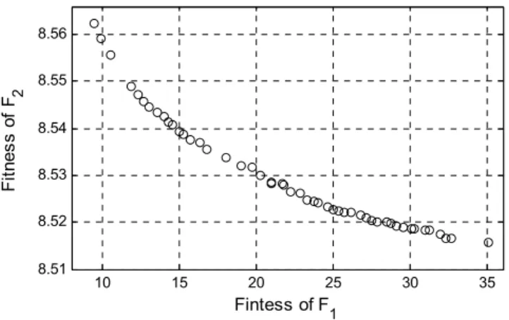
For the very first execution of the program, a wider solution space can be given and after getting the solution one can shorten the solution space nearer to the values obtained in the previous iteration. The final Pareto solution surface is shown in Fig. 6 where the Pareto solutions are shown with the marker ‘o’.
B. Best Compromise Solution
In the present paper, a Fuzzy-based approach is applied to select the best compromise solution from the obtained Pareto set. The j-th objective function of a solution in a Pareto set fj
10 15 20 25 30 35 8.51 8.52 8.53 8.54 8.55 8.56 Fintess of F1 Fi tnes s o f F 2
Fig. 6 Pareto solution surface
is represented by a membership function
P
jdefined as [16]:°
°
¿
°
°
¾
½
°
°
¯
°
°
®
t
d
max max min min max max min,
0
,
,
1
j j j j j j j j j j j jf
f
f
f
f
f
f
f
f
f
f
P
(22)where
f
jmax andf
jminare the maximum and minimum values of the j-th objective function, respectively.For each solution i, the membership function
P
i is calculated as:¦ ¦
¦
m i n j i j n j i j i 1 1 1P
P
P
(23)where, n is the number of objectives functions and m is the number of solutions. The solution having the maximum value of
P
iis the best compromise solution.Using the above approach the best compromise solution is obtained as:
KT=55.8577, T1= 0.1684 s, T2= 0.0637 s, T3= 0.3126 s and T4= 0.3126 s
C. Eigenvalue Analysis
To assess the effectiveness and robustness of the proposed stabilizers, three different loading conditions given in Table II are considered. The system electromechanical mode eigenvalues without and with the proposed controllers are shown in Table III. Table III also shows the system electromechanical eigenvalues without optimized TCSC controller parameters. In this case the values are randomly chosen as:
KT =40, T1=0.2 s, T2=0.05 s, T3=0.25 s and T4 =0.05 s.
It is clear from Table III that the open loop system is unstable at all the loading conditions because of negative damping of electromechanical mode (s = 0.2655, 0.0278, 0.4864 for nominal, light and heavy loading respectively). Without optimized TCSC controller parameters the system stability is maintained as the electromechanical mode eigenvalue shift to the left of the line in splane (s = 0.0081, -1.1828, -0.0088 for nominal, light and heavy loading respectively) for all loading conditions. It is also clear that MOGA optimized TCSC controller shifts substantially the electromechanical mode eigenvalue to the left of the line (s = -3.6835, -3.8535, -2.3982 for nominal, light and heavy loading respectively) in the s-plane, which enhances the system stability and improves the damping characteristics of electromechanical mode.
TABLEII LOADING CONDITIONS CONSIDERED Loading conditions P (pu) Q (pu) į0 (deg.) Nominal loading 0.9 0.4652 68.51 Light loading 0.4 0.1286 30.06 Heavy loading 1.1 0.777 87.81
TABLEIII SYSTEM ELECTROMECHANICAL MODE EIGENVALUES Loading Conditions Without control Without optimized TCSC With MOGA optimized TCSC Nominal loading 0.2655r 4.9846i -0.0081r 0.0283i -3.6835r 1.8176i Light loading 0.0278r 5.5445i -1.1828r 4.1526i -3.8535r 3.3751i Heavy loading 0.4864r 3.9793i -0.0088r 0.0209i -2.3982r 1.5389i D. Simulation Results
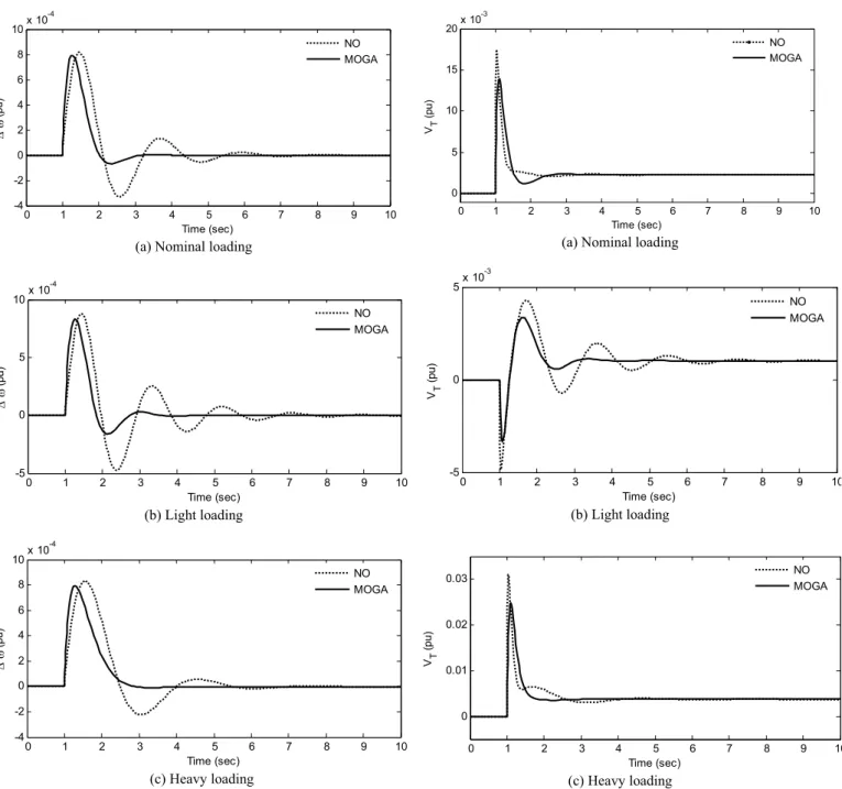
In order to verify the effectiveness of the proposed approach, the performance of the MOGA optimized TCSC controller is tested for different loading conditions and compared with the case where the TCSC-based controller parameters are not optimized (i.e. using the randomly chosen values as the TCSC-based controller parameters). A 10 % step increase in mechanical power input at t =1.0 sec is considered. The response with TCSC without optimization are shown in dotted lines (with legend NO); and the responses with MOGA optimized TCSC controllers are shown with solid lines (with legend MOGA). The system is unstable without control for the above contingency and the responses are not shown in figures. The system speed deviation and terminal voltage response for the above contingency at all the loading condition are shown in Figs. 7 and 8 respectively. These simulation results illustrate the effectiveness and robustness of proposed design approach. It is clear that the proposed TCSC controller has good damping characteristics to low frequency oscillations and stabilizes the system quickly for all loading conditions.
0 1 2 3 4 5 6 7 8 9 10 -4 -2 0 2 4 6 8 10x 10 -4 Time (sec) 'Z (pu) NO MOGA
(a) Nominal loading
0 1 2 3 4 5 6 7 8 9 10 -5 0 5 10x 10 -4 Time (sec) 'Z (pu ) NO MOGA (b) Light loading 0 1 2 3 4 5 6 7 8 9 10 -4 -2 0 2 4 6 8 10x 10 -4 Time (sec) 'Z (pu) NO MOGA (c) Heavy loading
Fig. 7 Speed deviation responses for a 10 % step increase in mechanical power input (a) nominal loading (b) light loading (c) heavy loading.
VI. CONCLUSIONS
In this study, the performance improvement of a power system by optimal design of a TCSC-based controller is presented and discussed. The design objective is to improve both rotor angle stability and system voltage profile. A Genetic Algorithm (GA) based solution technique is applied to generate a Pareto set of global optimal solutions to the given multi-objective optimisation problem. Further, a fuzzy-based membership value assignment method is employed to choose the best compromise solution from the obtained Pareto solution set. Eigenvalue analysis and simulation results are
0 1 2 3 4 5 6 7 8 9 10 0 5 10 15 20x 10 -3 Time (sec) VT (pu ) NO MOGA
(a) Nominal loading
0 1 2 3 4 5 6 7 8 9 10 -5 0 5x 10 -3 Time (sec) VT (pu) NO MOGA (b) Light loading 0 1 2 3 4 5 6 7 8 9 10 0 0.01 0.02 0.03 Time (sec) VT (pu) NO MOGA (c) Heavy loading
Fig. 8 Terminal voltage responses for a 10 % step increase in mechanical power input (a) nominal loading (b) light loading (c) heavy loading.
presented under various loading conditions to show the effectiveness and robustness of the proposed approach.The proposed method is valuable for the design of the interactive decision making. The decision makers can choose from the solutions in the Pareto-optimal set to find out the best solution according to the requirement and needs as the desired parameters of their controllers. The results show that evolutionary algorithms are effective tools for handling multi-objective optimization where multiple Pareto-optimal solutions can be found in one simulation run.
REFERENCES
[1] P. Kundur, Power System Stability and Control, McGraw-Hill, 1994 [2] A. D Del Rosso, C. A Canizares and V.M. Dona, “A study of TCSC
controller design for power system stability improvement,” IEEE Trans. Power Systs., vol-18, pp. 1487-1496. 2003.
[3] S. Panda, N. P. Padhy, R. N. Patel “Modeling, simulation and optimal tuning of TCSC controller”, International Journal ofSimulation Modelling. Vol. 6, No. 1, pp. 7-48, 2007.
[4] S. Panda, and N. P. Padhy “Comparison of Particle Swarm Optimization and Genetic Algorithm for FACTS-based Controller Design”, Applied Soft Computing. Vol. 8, pp. 1418-1427, 2008.
[5] S. Panda, S. C. Swain, A. K. Baliarsingh, C. Ardil, “Optimal Supplementary Damping Controller Design for TCSC Employing RCGA”,International Journal of Computational Intelligence, Vol. 5, No. 1, pp. 36-45, 2009.
[6] Sidhartha Panda and Narayana Prasad Padhy, “Application of Genetic Algorithm for PSS and FACTS based Controller Design”, International Journal of Computational Methods, Vol. 5, Issue 4, pp. 607-620, 2008. [7] S. Panda and R.N.Patel, “Damping Power System Oscillations by
Genetically Optimized PSS and TCSC Controller” International Journal of Energy Technology and Policy, Vol. 5, No. 4, pp. 457-474, 2007. [8] S. Panda, N.P.Padhy and R.N.Patel, “Robust Coordinated Design of PSS
and TCSC using PSO Technique for Power System Stability Enhancement”, Journal of Electrical Systems, Vol. 3, No. 2, pp. 109-123, 2007.
[9] Sidhartha Panda, N.P.Padhy, “Thyristor Controlled Series Compensator-based Controller Design Employing Genetic algorithm: A Comparative Study” International Journal of Electronics, Circuits and Systems, Vol. 1, No. 1, pp. 38-47, 2007.
[10] C. A .C. Coello, “A comprehensive survey of evolutionary-based multiobjective optimization techniques”, Knowledge and Information Systems, Vol. 1, No. 3, pp. 269-308. , 1999.
[11] V. Chankong and Y. Haimes, Multiobjective Decision Making Theory and Methodology, New York: North-Holland. 1983.
[12] C. M Fonseca, and P. J. Fleming, ‘Genetic algorithms for multiobjective optimization: formulation, discussion and generalization, Proceedings of the Fifth International Conference on Genetic Algorithms, San Mateo California. pp. 416-423, 1993.
[13] H. F. Wang, F. J. Swift, A Unified Model of FACTS Devices in Damping Power System Oscillations Part-1: Single-machine Infinite-bus Power Systems, IEEE Trans. Power Delivery, Vol. 12, No. 2, pp. 941-946, 1997.
[14] S. S. Rao, Optimization Theory and Application,New Delhi: Wiley Eastern Limited, 1991.
[15] D. E. Goldberg, Genetic Algorithms in Search, Optimization, and Machine Learning, Addison-Wesley, 1989.
[16] Sidhartha Panda “Multi-objective evolutionary algorithm for SSSC-based controller design”, Electric Power System Research., Vol. 79, Issue 6, pp. 937-944, 2009.
Sidhartha Panda is a Professor at National Institute of Science and Technology, Berhampur, Orissa, India. He received the Ph.D. degree from Indian Institute of Technology, Roorkee, India in 2008, M.E. degree in Power Systems Engineering in 2001 and B.E. degree in Electrical Engineering in 1991. Earlier he worked as Associate Professor in KIIT University, Bhubaneswar, India and VITAM College of Engineering, Andhra Pradesh, India and Lecturer in the Department of Electrical Engineering, SMIT, Orissa, India.His areas of research include power system transient stability, power system dynamic stability, FACTS, optimization techniques, distributed generation and wind energy.
S. C. Swain received his M.E. degree from UCE Burla in 2001. Presently he is working as an Assistant Professor in the Department of Electrical Engineering, School of technology, KIIT,University, Bhubaneswar, Orissa, India. He is working towards his PhD in KIIT
University in the area of Application of Computational Intelligent Techniques to Power System.
A. K. Baliarsingh is working as an Assistant Professor in the Department of Electrical Engineering, Orissa Engineering College, Bhubaneswar, Orissa,
India. He is working towards his PhD in KIIT University in the area of Application of Computational Intelligent Techniques to Power System Stability Problems and Flexible AC Transmission Systems controller design.
Dr. A. K. Mohanty is an Ex-Professor in N.I.T.Rourkela.Now he is working as a Professor in Electrical Engg. Deptt. at KIIT UNIVERSITY Bhubaneswar.
Cemal Ardil is with National Academy of Aviation, AZ1045, Baku, Azerbaijan, Bina, 25th km, NAA