Politecnico di Torino
Porto Institutional Repository
[Article] On the Selective Laser Melting (SLM) of the AlSi10Mg Alloy:
Process, Microstructure, and Mechanical Properties
Original Citation:
Francesco Trevisan; Calignano, Flaviana; Lorusso, Massimo; Pakkanen, Jukka; Aversa, Alberta;
Ambrosio, Elisa Paola; Lombardi, Mariangela; Fino, Paolo; Diego, Manfredi (2017).
On the Selective
Laser Melting (SLM) of the AlSi10Mg Alloy: Process, Microstructure, and Mechanical Properties.
In:
MATERIALS
, vol. 10 n. 76, pp. 1-23. - ISSN 1996-1944
Availability:
This version is available at :
http://porto.polito.it/2666241/
since: March 2017
Publisher:
MDPI
Published version:
DOI:
10.3390/ma10010076
Terms of use:
This article is made available under terms and conditions applicable to Open Access Policy Article
("Attribuzione 3.0 Italia") , as described at
http://porto.polito.it/terms_and_conditions.html
Porto, the institutional repository of the Politecnico di Torino, is provided by the University Library
and the IT-Services. The aim is to enable open access to all the world. Please
share with us
how
this access benefits you. Your story matters.
Review
On the Selective Laser Melting (SLM) of the
AlSi10Mg Alloy: Process, Microstructure,
and Mechanical Properties
Francesco Trevisan1,2, Flaviana Calignano2, Massimo Lorusso2, Jukka Pakkanen1,2, Alberta Aversa1, Elisa Paola Ambrosio2, Mariangela Lombardi1, Paolo Fino1,2 and Diego Manfredi2,*
1 DISAT, Department of Applied Science and Technology, Politecnico di Torino,
Corso Duca degli Abruzzi 24, 10129 Torino, Italy; [email protected] (F.T.);
[email protected] (J.P.); [email protected] (A.A.); [email protected] (M.L.); [email protected] (P.F.)
2 Centre for Sustainable Future Technologies @PoliTo, Istituto Italiano di Tecnologia,
Corso Trento 21, 10129 Torino, Italy; [email protected] (F.C.); [email protected] (M.L.); [email protected] (E.P.A.)
* Correspondence: [email protected]; Tel.: +39-011-050-91930 Academic Editor: Guillermo Requena
Received: 21 October 2016; Accepted: 12 January 2017; Published: 18 January 2017
Abstract:The aim of this review is to analyze and to summarize the state of the art of the processing of aluminum alloys, and in particular of the AlSi10Mg alloy, obtained by means of the Additive Manufacturing (AM) technique known as Selective Laser Melting (SLM). This process is gaining interest worldwide, thanks to the possibility of obtaining a freeform fabrication coupled with high mechanical properties related to a very fine microstructure. However, SLM is very complex, from a physical point of view, due to the interaction between a concentrated laser source and metallic powders, and to the extremely rapid melting and the subsequent fast solidification. The effects of the main process variables on the properties of the final parts are analyzed in this review: from the starting powder properties, such as shape and powder size distribution, to the main process parameters, such as laser power and speed, layer thickness, and scanning strategy. Furthermore, a detailed overview on the microstructure of the AlSi10Mg material, with the related tensile and fatigue properties of the final SLM parts, in some cases after different heat treatments, is presented.
Keywords:Additive Manufacturing (AM); Selective Laser Melting (SLM); AlSi10Mg; microstructure; mechanical properties
1. Introduction
Additive Manufacturing (AM) technologies, combined with the development of new materials and the already available processes, have the potential of revolutionizing the way of perceiving the manufacturing of products. Generally speaking, the term AM refers to metals, while the term 3D printing refers to polymers. At the end of the 80s, industrial designers began to use 3D printing technologies to make prototypes of their projects in order to evaluate problems related to their form, fit, and functions, as well as their usability. In the late 90s and at the beginning of 2000s, 3D printing and AM technologies started to be employed in the production of final components, thanks to improved reliability and reproducibility of the processes, and in the case of metallic materials, thanks to the employment of powerful energy sources that were able to consolidate these materials. Today, AM has substituted certain conventional metal manufacturing processes, such as casting and forging, in some specific production routes, particularly in the aerospace and motor racing application fields. In fact,
Materials2017,10, 76 2 of 23
in these application fields its main benefits, such as the absence of constraints in the manufacturing design, shape freedom, high complexity of the components, combination of multiple parts into one part, production of functionally graded materials, reduced tooling requirements, and the possibility of production on demand, have been exploited [1–3].
In particular, over the last decade, an impressive development of the AM technology for metals named Selective Laser Melting (SLM) has taken place in order to produce complex shaped components in several structural alloys to meet the high demand requirements for applications in different fields, such as the aerospace, automotive, and biomedical sectors [4,5]. Moreover, it has been demonstrated, in recent literature, that SLM can also be used to fabricate metal matrix composites (MMCs) [6–8]. This goal can in part be reached through the development of new materials, with better properties than the same ones obtained by means of conventional processes, and in part through improvements in the control, accuracy, and reliability of the SLM process.
The SLM process, which has recently been defined as the laser powder bed fusion process, according to ISO/ASTM 52900 [9], and which is also known by the trade names Direct Metal Laser Sintering (DMLS) or LaserCUSING, directly produces homogenous metal objects, layer by layer, from 3D CAD data, by selectively melting fine layers of metal powder with a laser beam [10]. As SLM is an additive manufacturing technique, it allows structural parts to be built with the required strength and stiffness, but with considerably lighter weight than their conventionally manufactured counterparts [10–13]. For example, Jurg et al. [14] applied the SLM technology to the fabrication of a micro-lattice structure, adopted for the coolant jacket wall of a rocket engine, obtaining a net reduction of the overall dry mass of the engine, compared to previous designs. All these structures could be used to further reduce the airframe structure weight, guaranteeing at the same time the strength in resisting aerodynamic forces [15]. As observed by Klahn et al. [16], as far as SLM is concerned, only a few limitations to the design remain, and further development could be focused on improvements in the design to obtain a better performance. The development of specific application design guidelines should be taken into account to describe the best practices in order to resolve certain mechanical challenges [17–19].
As far as the lightweight materials that are currently available for SLM processing are concerned, the most frequently explored are titanium and aluminum alloys. The former ones, such as commercially pure Ti (CP-Ti) and Ti-6Al-4V (Ti64), have been in particular developed for biomedical applications, due to their high corrosion resistance and fatigue properties at room temperature [20,21]. On the other hand, the most frequently investigated Al alloys are Al–Si alloys, which represent 80% of aluminum casting alloys, thanks to their high fluidity, high weldability, good corrosion resistance, and low coefficient of thermal expansion. The binary Al-Si system is a eutectic system with about 12 wt % Si, as the eutectic composition is at 577◦C [22,23]. Al-Si alloys are defined as eutectic alloys when the Si is in the range 11–13 wt %, as hypoeutectic alloys when the Si is less than 11 wt % and as hypereutectic alloys when the Si is more than 13 wt % [24]. The strengthening of these alloys is generally possible, through the addition of other alloying elements, such as Mg and Cu, which make the Al-Si alloys hardenable either by means of a heat treatment, or by using rapid solidification techniques, in which the cooling rate is higher than 102K·s−1, such as melt spinning, which leads to a refinement of the microstructure [25]. However it is only possible to obtain ribbons or rods with melt spinning. In the SLM process, the interaction between the focused laser beam and the powders leads to an extremely high temperature gradient, with very high heating and cooling rates, as estimated in previous studies [26,27], thus a strong refinement is obtained in the eutectic Si phase and consequently a greater hardness and strength is measured for the final parts. Li et al. [27] performed a systematic investigation on the influence of the solution heat treatment on the eutectic microstructure and on the strength and ductility of an Al-12Si alloy produced by means of SLM. The results show that the size of the eutectic Si particles increases as the solution treatment time is increased. On the basis of a detailed Transmission Electron Microscopy (TEM) study, it was found that spherical Si particles, with a diameter of less than 100 nm, formed at the Al grain boundaries as a result of the extremely high cooling rate
that is reached during SLM. Other interesting studies on Al–Si alloys have been summarized in a very comprehensive review by Olakanmi and co-workers [28]: the effects of the powders and the effect of the processing parameters on the densification mechanism and microstructural evolution in laser obtained samples have in particular been deeply analyzed.
As already stated, there is currently a great demand for Al–Si–Mg alloys for many applications, such as for motor racing, the automotive industry, and for aerospace and heat exchanger products, due to their high mechanical properties, like hardness and strength, in the heat treated state [29]. These alloys were traditionally used for lightweight and thin walled casting parts, and for any components with a complex geometry subjected to high loads [30]. Among these alloys, as reported by Sercombe in his review on Al and Al composites by SLM, the most frequently investigated is the AlSi10Mg alloy, which is similar to A360. Many studies have been performed on these alloys, considering such aspects as the starting powders up to the possible final applications of lightweight lattice structures [7,20,31,32]. The aim of the present review is to focus the attention on this Al hardenable alloy trying to draw up a comprehensive state-of-the-art portrait, and to correlate the effects of the main variables of the SLM process on the microstructural and mechanical characteristics of the alloy. Finally, this review also aspires to resume post process heat treatments developed for conventionally manufactured materials and applied on SLM materials, in order to analyze what effect these treatments would have on the overall mechanical behavior.
2. SLM Process
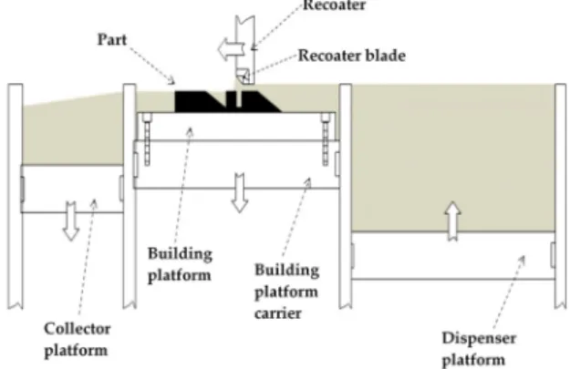
The SLM process belongs to the class of powder bed fusion technologies known as selective laser sintering (SLS) and electron beam melting (EBM). The SLM process is schematically represented in Figure1: a layer of powder (generally 20–60µm thick) is spread over the building area, using a powder spreading system, which is commonly known as a recoater blade. Once the layer of powder is deposited on the building platform, which can be pre-heated, a laser source is directed onto the powder bed, and selectively fuses the material. The entire region of material subjected to the impinging heat energy is melted to a greater depth than the layer thickness. This type of consolidation is very effective in creating well-bonded, high density structures [33,34]. After completing a layer, the build platform is lowered by one layer of thickness, and a new layer of powder is laid, levelled, and melted. The process is repeated until a complete part is built.
Materials 2017, 10, 76 3 of 23
[28]: the effects of the powders and the effect of the processing parameters on the densification mechanism and microstructural evolution in laser obtained samples have in particular been deeply analyzed.
As already stated, there is currently a great demand for Al–Si–Mg alloys for many applications, such as for motor racing, the automotive industry, and for aerospace and heat exchanger products, due to their high mechanical properties, like hardness and strength, in the heat treated state [29]. These alloys were traditionally used for lightweight and thin walled casting parts, and for any components with a complex geometry subjected to high loads [30]. Among these alloys, as reported by Sercombe in his review on Al and Al composites by SLM, the most frequently investigated is the AlSi10Mg alloy, which is similar to A360. Many studies have been performed on these alloys, considering such aspects as the starting powders up to the possible final applications of lightweight lattice structures [7,20,31,32]. The aim of the present review is to focus the attention on this Al hardenable alloy trying to draw up a comprehensive state-of-the-art portrait, and to correlate the effects of the main variables of the SLM process on the microstructural and mechanical characteristics of the alloy. Finally, this review also aspires to resume post process heat treatments developed for conventionally manufactured materials and applied on SLM materials, in order to analyze what effect these treatments would have on the overall mechanical behavior.
2. SLM Process
The SLM process belongs to the class of powder bed fusion technologies known as selective laser sintering (SLS) and electron beam melting (EBM). The SLM process is schematically represented in
Figure 1: a layer of powder (generally 20–60 μm thick) is spread over the building area, using a
powder spreading system, which is commonly known as a recoater blade. Once the layer of powder is deposited on the building platform, which can be pre-heated, a laser source is directed onto the powder bed, and selectively fuses the material. The entire region of material subjected to the impinging heat energy is melted to a greater depth than the layer thickness. This type of consolidation is very effective in creating well-bonded, high density structures [33,34]. After completing a layer, the build platform is lowered by one layer of thickness, and a new layer of powder is laid, levelled, and melted. The process is repeated until a complete part is built.
Figure 1. Schematic representation of the Selective Laser Melting (SLM) process.
The SLM process involves a great variety of factors and variables that determine the final properties of the components, which are summarized in Table 1: they can be divided into two main categories: powder properties and process parameters. Each factor has a direct influence on the densification, microstructure, and mechanical properties of the final parts [7,35–38].
Figure 1.Schematic representation of the Selective Laser Melting (SLM) process.
The SLM process involves a great variety of factors and variables that determine the final properties of the components, which are summarized in Table 1: they can be divided into two main categories: powder properties and process parameters. Each factor has a direct influence on the densification, microstructure, and mechanical properties of the final parts [7,35–38].
Materials2017,10, 76 4 of 23
Table 1.Selective Laser Melting (SLM) variables.
Powder Properties Process Parameters
Particle shape Laser power Layer thickness Particle size and distribution Scanning speed Scanning strategy
Chemical composition Hatching distance Building orientation Thermal conductivity Protective atmosphere Gas flow
Melting temperature Laser beam radius Bed temperature Absorptivity/reflectivity Laser type
-2.1. Effects of the Principal Powder Properties on SLM Parts
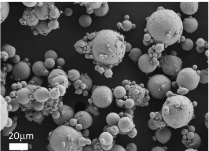
SLM is based on the processing of metallic powders, and the properties of the fabricated parts therefore depend above all on the starting material that is used. Among the possible shapes that are suitable for metallic powders, the spherical one is preferred: it in fact allows a good flowability and high bed density. An example of a typical Al powder for an SLM process is shown in Figure2: gas atomized powders are generally preferred for AM processes, because of their spherical shape. Water atomizing produces cheaper powders than gas atomizing, but they have a more irregular shape, and as a consequence, the flow time and packing density are reduced [39]. A good powder flowability is required to achieve constant thickness powder layers, that assure a uniform laser beam absorption in the building area [40]. Thicker regions of the powder bed may lead to insufficient re-melting depths in the previous layer, as well as favoring melt track instability effects [41].
Materials 2017, 10, 76 4 of 23
Table 1. Selective Laser Melting (SLM) variables.
Powder Properties Process Parameters
Particle shape Laser power Layer thickness
Particle size and distribution Scanning speed Scanning strategy
Chemical composition Hatching distance Building orientation
Thermal conductivity Protective atmosphere Gas flow
Melting temperature Laser beam radius Bed temperature
Absorptivity/reflectivity Laser type -
2.1. Effects of the Principal Powder Properties on SLM Parts
SLM is based on the processing of metallic powders, and the properties of the fabricated parts therefore depend above all on the starting material that is used. Among the possible shapes that are suitable for metallic powders, the spherical one is preferred: it in fact allows a good flowability and high bed density. An example of a typical Al powder for an SLM process is shown in Figure 2: gas atomized powders are generally preferred for AM processes, because of their spherical shape. Water atomizing produces cheaper powders than gas atomizing, but they have a more irregular shape, and as a consequence, the flow time and packing density are reduced [39]. A good powder flowability is required to achieve constant thickness powder layers, that assure a uniform laser beam absorption in the building area [40]. Thicker regions of the powder bed may lead to insufficient re-melting depths in the previous layer, as well as favoring melt track instability effects [41].
Figure 2. Field Emission Scanning Electron Microscopy (FESEM) image of gas atomized aluminum powders: the particles are spherical and their size varies between 1 and 30 μm.
Sercombe et al. [7] explored some of the inherent difficulties of working with aluminum alloys. They highlighted how the laser melting of aluminum poses several challenges for the production of high density components, because of the characteristics of the powder, which include stability of the oxide layer, poor flowability, high reflectivity, and high thermal conductivity. Spierings et al. [42] compared the densification and the mechanical strength of three stainless steel powders with different particle size distributions. They demonstrated how a certain amount of fine particles is needed in SLM processes in order to optimize the part properties (e.g., density, mechanical strength, surface roughness), while large particles determine the minimum layer thickness value, and are beneficial for the elongation at break of the final part. The size of the powder particles also influences the physical interactions between the powder and the laser beam. Fine powder particles in fact have a high surface energy, which in turn leads to superior densification kinetics, while large particles require higher incident laser density to be melted correctly [43]. As observed by Liu et al. [40], a possible direct correlation exists between the powder bed density and the part density: powders with
Figure 2.Field Emission Scanning Electron Microscopy (FESEM) image of gas atomized aluminum powders: the particles are spherical and their size varies between 1 and 30µm.
Sercombe et al. [7] explored some of the inherent difficulties of working with aluminum alloys. They highlighted how the laser melting of aluminum poses several challenges for the production of high density components, because of the characteristics of the powder, which include stability of the oxide layer, poor flowability, high reflectivity, and high thermal conductivity. Spierings et al. [42] compared the densification and the mechanical strength of three stainless steel powders with different particle size distributions. They demonstrated how a certain amount of fine particles is needed in SLM processes in order to optimize the part properties (e.g., density, mechanical strength, surface roughness), while large particles determine the minimum layer thickness value, and are beneficial for the elongation at break of the final part. The size of the powder particles also influences the physical interactions between the powder and the laser beam. Fine powder particles in fact have a high surface
energy, which in turn leads to superior densification kinetics, while large particles require higher incident laser density to be melted correctly [43]. As observed by Liu et al. [40], a possible direct correlation exists between the powder bed density and the part density: powders with a wider range of particle sizes providing a higher powder bed density and generating higher density parts under low laser energy intensities.
Another fundamental aspect is the chemical composition of the powders. They often have a high degree of contamination, which can be caused by moisture, organics, adsorbed gases, and oxide films that are present on the particle surface, due to their high surface area per unit volume: these contaminants not only inhibit the successful densification of the material, but also degrade the mechanical properties of the consolidated products [37,39,44]. Li et al. [45] investigated the chemical composition of the surface of A1-12Si alloy particles, before and after a drying treatment at 100◦C for 1 h. From the results, it appeared that adopting a drying treatment enabled the fabricated material density to be increased by more than 99%. Furthermore, through X-ray Photoelectron Spectroscopy (XPS) analysis, they found that the as-received powder surface contained Al metal and carbonate hydroxide (Al–O–CHxO). After drying, the presence of carbonate hydroxide decreased, while the amount of Al metal increased: the reduction in Al–O–CHxO was probably caused by the loss of moisture (H2O) from the powder surface. Finally, it is important to point out that Al reacts with moisture to produce Al oxide at temperatures of between 500 and 800◦C, while Al hydroxide is produced at temperatures over 800◦C. Both are known to form significantly during the SLM process, thus hindering the densification mechanism and favoring pore formation in the fabricated parts [37,43].
2.2. Effects of the Main Process Parameters on SLM Parts
As stated before, in the SLM process, a laser source is directed onto the powder bed, transferring heat energy to it and melting the material. In order to define the correct amount of energy that needs to be delivered to the powder bed, Simchi et al. [43] analyzed the combinations of parameters that influence the energy input during SLM. Assuming the material properties as fixed, the amount of energy transferred to the powder bed, during the laser irradiation-material interaction period, depends on the number of exposures and time between each exposure. The process parameters that have the most influence on the intensity and on the method adopted to deliver energy to a single layer of powder are: laser power (P), scanning speed (v), scan line spacing or hatching distance (h), and layer thickness (t). In order to evaluate the combined effect of these parameters, a factor called energy density (ψ) [46] was defined, with a Joule/millimetre3(J/mm3) unit, according to Equation (1):
ψ=P/(v×h×t) (1)
Many authors have used this approach to study the SLM process of different materials [30,32,47]. For example, Meier et al. [47] focused on the processing map of 316 L stainless steel powders. Varying the process parameters, they found that the energy density range that was suitable to achieve an optimal combination of material density and surface quality was between 40 and 90 J/mm3, while an excessive delivery of the energy density resulted in melt pool instability and complications, such as balling. This phenomenon can be described as the sphereodization of the liquid melt pool during laser interaction with the powder bed [33,48].
On the other hand, taking into account that many commercial SLM machines keep the layer thickness value fixed, other authors [49–51] have not considered it for the process parameter optimization. As a result, they considered a surface energy density approach. Olakanmi et al. [39], for instance, studied the processing map for Al, Al-Mg, and Al-Si powders, investigating the different behavior of aluminum alloys on the basis of the energy inputs during SLM. The processing window was investigated by employing a laser power of between 20 and 240 W, and scanning speeds of between 20 and 250 mm/s, with a constant hatching distance of 0.1 mm. Four regions of densification behavior were identified for all the powders, and the findings can be summarized as follows:
Materials2017,10, 76 6 of 23
• the region labelled “no marking” was related to a very low energy density (lower than 3.2 J/mm2), which did not permit an inter-particulate bonding between the particles;
• the “partial marking” region was characterized by an agglomerate network with a large amount of small, open and deep porosities, and can be related to the low energy density value that was used (between 3.3 and 10 J/mm2). The low energy input was not in fact able to generate an adequate liquid phase amount that would enable the full inter-bonding of the particles;
• dense parts (60%–80% density) were found in the “good consolidation” region, and were ascribed to the adoption of higher energy densities of between 12 and 30 J/mm2. The enhanced density was probably related to the higher powder bed temperature and lower viscosity of the melt pool of the processed powders, which facilitated the formation of an adequate amount of liquid phase, and this in turn promoted full melting;
• the occurrence of an “excessive balling” region was due to the high energy densities that were used to fabricate the parts (above 30 J/mm2), which favored the generation of an excessive liquid phase, and this in turn resulted in melt track instability and balling.
The hatching distance value has not been considered in the calculation of the energy density amount delivered to the powder bed in other studies [48,52–56]. In this way, the process window for the part processing was evaluated in terms of linear energy density. Starting from the consideration that the properties of manufactured parts depend to a great extent on each single laser-melted track and each single layer, Yadroitsev et al. [52], studied the effects of the scanning speed and laser power on the formation of single tracks for 316 L stainless steel, tool steel H13, copper alloy CuNi10, and superalloy Inconel 625. The results showed that the process has a stability zone where the track is continuous and an instability zone for low scanning speeds. The range of the optimal scanning speed is larger for higher laser power, and it narrows for high thermal conductivity materials.
The final SLM components showed different hardness and tensile properties from cast or wrought parts in similar alloys, and this was primarily due to the ultrafine microstructure, with its complex crystal growth directions, and to residual thermal stresses [45,57,58]. SLM parts generally present higher tensile strength, with anisotropy that depends on the building direction, than their cast counterparts [26]. The superior strength values that as-built components have are usually explained by adopting the Hall-Petch equation [59] reported in Equation (2):
σ0=σi+k/d1/2 (2)
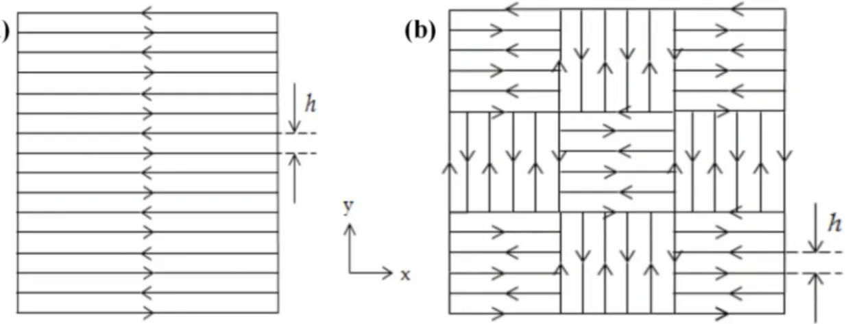
The equation highlights that the strength of the material (σ0) is given by the sum of the frictional stress (σi) and a factor (k) times the inverse of the square root of the grain size (d). The local heating and cooling rates, during the melting of the powders, are very high (103–108K·s−1) [45,60], and this leads to a non-equilibrium solidification process, with the development of ultrafine microstructures [61], extended solid solubility, and the possible formation of non-equilibrium phases. The relationship between the residual stress and the interfacial microstructure in a selective laser melted Al12Si/SiC composite was studied using confocal Raman microscopy by Li et al. [45]. The tensile stress in the SiC was found to be higher in the build direction (Z) than in the (X–Z) direction perpendicular to the build direction, while no such difference was observed in Si. The underlying reason for this difference was ascribed to the Gaussian distribution of the laser energy density and to stress relief through the interfacial reaction. Furthermore, the complex heat transfer conditions in the melt pool cause the preferential growth of grains, and this leads to a heterogeneous microstructure [26,59–63]. The presence of columnar grains, which are characteristic of some SLM materials, modifies the mechanical behavior of the material during the stress application, and thus generates anisotropy in the mechanical response. The scanning strategy, which is the geometrical pattern that the laser beam follows during the hatching to melt and consolidate a section onto a layer, also influences the porosity and microstructure in SLM materials to a great extent [49,64–66]. Figure3shows two main scanning strategies. Moreover, adopting the correct scanning strategy helps to create final parts that are free from distortions, warping,
porosities, and anisotropy. Guan et al. [67] studied the tensile properties of SLM 304 stainless steel, varying the hatch angle over 90◦, 105◦, 120◦, 135◦, and 150◦, while keeping the other process parameters constant. From the results, they found that samples fabricated at the maximum interval number of layers, the test pieces fabricated at the hatch angle of 105◦, have excellent yield strength and ultimate tensile strength due to a reduction in the residual stresses and anisotropy. Cheng et al. [68] developed a 3D sequentially-coupled finite element (FE) model to investigate the thermomechanical responses in the SLM process. The model was applied to different scanning strategies, and their effects on part temperature, stress, and deformation were evaluated. It was observed that the 45◦line scanning case had the smallest deformation. Lu et al. [69] investigated the island size effect on the residual stress of SLM Inconel 718 parts. The results showed that a 5×5 mm2island size sample had a lower residual stress than a sample with 7×7 mm2or 3×3 mm2island sizes. Su et al. [66] studied three different types of track overlapping regimes (intra-layer, inter-layer and mixed overlapping regimes) in order to select the best approach to improve fabrication efficiency as well as the relative density of the SLM process using 316 stainless steel (Figure4). The results showed that an inter-layer overlapping regime could be reached when the track space was below 0.2 mm and the other parameters were kept constant; parts with the highest relative density were thus obtained.
Materials 2017, 10, 76 7 of 23
investigate the thermomechanical responses in the SLM process. The model was applied to different scanning strategies, and their effects on part temperature, stress, and deformation were evaluated. It was observed that the 45° line scanning case had the smallest deformation. Lu et al. [69] investigated the island size effect on the residual stress of SLM Inconel 718 parts. The results showed that a
5 × 5 mm2 island size sample had a lower residual stress than a sample with 7 × 7 mm2 or 3 × 3 mm2
island sizes. Su et al. [66] studied three different types of track overlapping regimes (intra-layer, inter-layer and mixed overlapping regimes) in order to select the best approach to improve fabrication efficiency as well as the relative density of the SLM process using 316 stainless steel (Figure 4). The results showed that an inter-layer overlapping regime could be reached when the track space was below 0.2 mm and the other parameters were kept constant; parts with the highest relative density were thus obtained.
Figure 3. (a) Parallel scan line method; and (b) chessboard or island scanning strategy.
Figure 4. Three types of overlapping regimes under inter-layer stagger scanning strategy: (a) intra-layer; (b) inter-layer; and (c) mixed overlapping regime
Another very influential and deeply investigated factor that affects the microstructure as well as the hardness values and tensile strengths of SLM materials is the building orientation of the part, which is graphically explained in Figure 5. The orientation can modify the microstructural evolution of the material, and can introduce anisotropy and defects [30,32,70,71]. Yadroitsev et al. [71] studied how the tensile properties of a specimen produced in Inconel 625 varied according to the different building orientations, underlining how the vertical specimens had a lower elastic modulus than the horizontal ones. The reason for this anisotropy was correlated to the higher number of defects, which were caused by a higher concentration of residual stresses, as was also observed in other studies [61].
Figure 3.(a) Parallel scan line method; and (b) chessboard or island scanning strategy.
Materials 2017, 10, 76 7 of 23
investigate the thermomechanical responses in the SLM process. The model was applied to different scanning strategies, and their effects on part temperature, stress, and deformation were evaluated. It was observed that the 45° line scanning case had the smallest deformation. Lu et al. [69] investigated the island size effect on the residual stress of SLM Inconel 718 parts. The results showed that a
5 × 5 mm2 island size sample had a lower residual stress than a sample with 7 × 7 mm2 or 3 × 3 mm2
island sizes. Su et al. [66] studied three different types of track overlapping regimes (intra-layer, inter-layer and mixed overlapping regimes) in order to select the best approach to improve fabrication efficiency as well as the relative density of the SLM process using 316 stainless steel (Figure 4). The results showed that an inter-layer overlapping regime could be reached when the track space was below 0.2 mm and the other parameters were kept constant; parts with the highest relative density were thus obtained.
Figure 3. (a) Parallel scan line method; and (b) chessboard or island scanning strategy.
Figure 4. Three types of overlapping regimes under inter-layer stagger scanning strategy: (a) intra-layer; (b) inter-layer; and (c) mixed overlapping regime
Another very influential and deeply investigated factor that affects the microstructure as well as the hardness values and tensile strengths of SLM materials is the building orientation of the part, which is graphically explained in Figure 5. The orientation can modify the microstructural evolution of the material, and can introduce anisotropy and defects [30,32,70,71]. Yadroitsev et al. [71] studied how the tensile properties of a specimen produced in Inconel 625 varied according to the different building orientations, underlining how the vertical specimens had a lower elastic modulus than the horizontal ones. The reason for this anisotropy was correlated to the higher number of defects, which were caused by a higher concentration of residual stresses, as was also observed in other studies [61].
Figure 4.Three types of overlapping regimes under inter-layer stagger scanning strategy: (a) intra-layer; (b) inter-layer; and (c) mixed overlapping regime
Another very influential and deeply investigated factor that affects the microstructure as well as the hardness values and tensile strengths of SLM materials is the building orientation of the part, which is graphically explained in Figure5. The orientation can modify the microstructural evolution of the material, and can introduce anisotropy and defects [30,32,70,71]. Yadroitsev et al. [71] studied how the tensile properties of a specimen produced in Inconel 625 varied according to the different building orientations, underlining how the vertical specimens had a lower elastic modulus than the horizontal ones. The reason for this anisotropy was correlated to the higher number of defects, which were caused by a higher concentration of residual stresses, as was also observed in other studies [61].
Materials2017,10, 76 8 of 23
Materials 2017, 10, 76 8 of 23
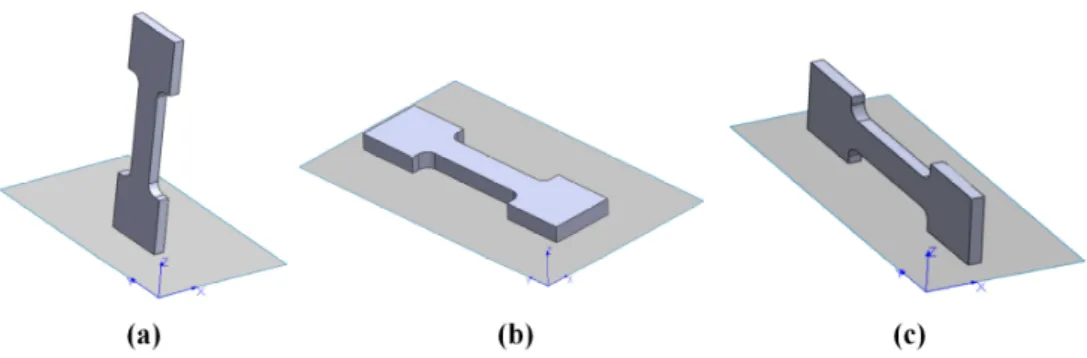
Figure 5. Examples of building orientations: (a) main direction parallel to the xz-plane; (b) main
direction parallel to the xy-plane; and (c) main direction parallel to the zx-plane. The z axis in the picture indicates the building direction, while the x and y axes identify the building platform plane.
However, the anisotropy in tensile properties found in the SLM parts has also been ascribed to the microstructural anisotropy caused by the local heat transfer condition, which can be determined by means of the scanning strategy [70]. Shifeng et al. [72] studied the influence of molten pool boundaries (MPBs) on the tensile properties of 316 L stainless steel SLM parts, built with different orientations. They identified two different MPB types in the component microstructure (Figure 6): “layer-layer” MPBs and “track-track” MPBs, generated by multi-layer and multi-track melt pool overlapping during the process, respectively. It was observed, from mechanical tests, that samples built along the z axis seemed to have lower tensile strength values and higher ductility than those built parallel to the xy-plane. The higher ductility could be related to the fact that the vertical samples have a larger number of slipping surfaces than the horizontal ones. In fact, when the vertical samples were loaded, slipping occurred simultaneously along both the “layer-layer” and “track-track” MPB surfaces, while in the case of horizontal samples, it only occurred along the “track-track” surfaces.
Figure 6. Schematic representation of different types of molten pool boundaries (MPBs): (a) single
MPB; (b) “layer-layer” MPB; and (c) “track-track” MPB
Chlebus et al. [73] observed that the microstructural anisotropy of Inconel 718 influenced the fracture modes and the tensile properties, due to the different orientations of the columnar grains in relation to the different loading directions. The direction of the columnar grains depended on the heat flow that developed during the process, which is closely correlated to the building strategy that is adopted.
The process atmosphere during SLM is another factor able to influence the amount and type of defects inside the material and therefore the mechanical behavior [28,37,74–77]. Fine metal powders are very sensitive to oxygen, due to their elevated surface areas, and the formation of an oxide layer alters the stability of the melt track during laser scanning, favoring balling phenomenon [28]. Moreover, when reactive powders, such as Al and Ti alloys, are considered, the O2 content should
always be kept below 0.1% to avoid dangerous reactions. Wang et al. [74] investigated the influence of three different inert atmospheres, using high purity argon (Ar), nitrogen (N2), and helium (He), on
the density and mechanical properties of Al-Si12 alloy parts. It appeared, from the results, that none of the different atmospheres significantly influenced the densification of the material. Only a slight
Figure 5. Examples of building orientations: (a) main direction parallel to thexz-plane; (b) main direction parallel to thexy-plane; and (c) main direction parallel to thezx-plane. Thezaxis in the picture indicates the building direction, while thexandyaxes identify the building platform plane.
However, the anisotropy in tensile properties found in the SLM parts has also been ascribed to the microstructural anisotropy caused by the local heat transfer condition, which can be determined by means of the scanning strategy [70]. Shifeng et al. [72] studied the influence of molten pool boundaries (MPBs) on the tensile properties of 316 L stainless steel SLM parts, built with different orientations. They identified two different MPB types in the component microstructure (Figure6): “layer-layer” MPBs and “track-track” MPBs, generated by multi-layer and multi-track melt pool overlapping during the process, respectively. It was observed, from mechanical tests, that samples built along thezaxis seemed to have lower tensile strength values and higher ductility than those built parallel to the
xy-plane. The higher ductility could be related to the fact that the vertical samples have a larger number of slipping surfaces than the horizontal ones. In fact, when the vertical samples were loaded, slipping occurred simultaneously along both the “layer-layer” and “track-track” MPB surfaces, while in the case of horizontal samples, it only occurred along the “track-track” surfaces.
Materials 2017, 10, 76 8 of 23
Figure 5. Examples of building orientations: (a) main direction parallel to the xz-plane; (b) main
direction parallel to the xy-plane; and (c) main direction parallel to the zx-plane. The z axis in the picture indicates the building direction, while the x and y axes identify the building platform plane.
However, the anisotropy in tensile properties found in the SLM parts has also been ascribed to the microstructural anisotropy caused by the local heat transfer condition, which can be determined by means of the scanning strategy [70]. Shifeng et al. [72] studied the influence of molten pool boundaries (MPBs) on the tensile properties of 316 L stainless steel SLM parts, built with different orientations. They identified two different MPB types in the component microstructure (Figure 6): “layer-layer” MPBs and “track-track” MPBs, generated by multi-layer and multi-track melt pool overlapping during the process, respectively. It was observed, from mechanical tests, that samples built along the z axis seemed to have lower tensile strength values and higher ductility than those built parallel to the xy-plane. The higher ductility could be related to the fact that the vertical samples have a larger number of slipping surfaces than the horizontal ones. In fact, when the vertical samples were loaded, slipping occurred simultaneously along both the “layer-layer” and “track-track” MPB surfaces, while in the case of horizontal samples, it only occurred along the “track-track” surfaces.
Figure 6. Schematic representation of different types of molten pool boundaries (MPBs): (a) single
MPB; (b) “layer-layer” MPB; and (c) “track-track” MPB
Chlebus et al. [73] observed that the microstructural anisotropy of Inconel 718 influenced the fracture modes and the tensile properties, due to the different orientations of the columnar grains in relation to the different loading directions. The direction of the columnar grains depended on the heat flow that developed during the process, which is closely correlated to the building strategy that is adopted.
The process atmosphere during SLM is another factor able to influence the amount and type of defects inside the material and therefore the mechanical behavior [28,37,74–77]. Fine metal powders are very sensitive to oxygen, due to their elevated surface areas, and the formation of an oxide layer alters the stability of the melt track during laser scanning, favoring balling phenomenon [28]. Moreover, when reactive powders, such as Al and Ti alloys, are considered, the O2 content should
always be kept below 0.1% to avoid dangerous reactions. Wang et al. [74] investigated the influence of three different inert atmospheres, using high purity argon (Ar), nitrogen (N2), and helium (He), on
the density and mechanical properties of Al-Si12 alloy parts. It appeared, from the results, that none of the different atmospheres significantly influenced the densification of the material. Only a slight
Figure 6.Schematic representation of different types of molten pool boundaries (MPBs): (a) single MPB; (b) “layer-layer” MPB; and (c) “track-track” MPB
Chlebus et al. [73] observed that the microstructural anisotropy of Inconel 718 influenced the fracture modes and the tensile properties, due to the different orientations of the columnar grains in relation to the different loading directions. The direction of the columnar grains depended on the heat flow that developed during the process, which is closely correlated to the building strategy that is adopted.
The process atmosphere during SLM is another factor able to influence the amount and type of defects inside the material and therefore the mechanical behavior [28,37,74–77]. Fine metal powders are very sensitive to oxygen, due to their elevated surface areas, and the formation of an oxide layer alters the stability of the melt track during laser scanning, favoring balling phenomenon [28]. Moreover, when reactive powders, such as Al and Ti alloys, are considered, the O2content should always be kept below 0.1% to avoid dangerous reactions. Wang et al. [74] investigated the influence of three different inert atmospheres, using high purity argon (Ar), nitrogen (N2), and helium (He), on the density and mechanical properties of Al-Si12 alloy parts. It appeared, from the results, that none of the
different atmospheres significantly influenced the densification of the material. Only a slight difference was observed in the microstructure of parts produced with He: high porosity regions, composed of 50µm diameter pores, were found in isolated areas. It appeared that the size of these areas did not affect the density measurement, but did influence the part ductility. Similar results were found in the study by Zhang et al. [78], who investigated how these three different protective atmospheres and hydrogen (H2), as a/the deoxidizer, mixed in different modes, influenced the porosity level of 316 L material. It was possible to note, from the results, that neither Ar nor N2influenced the porosity amount when used in pure form, instead, when He or H2was employed, the porosity increased by more than 10%. This phenomenon can be explained considering the different interactions between gases and the laser source, that is, in plasma conditions. The plasma generated from He or H2is located at a higher position, with respect to the melt pool, than that generated by Ar or N2, because of the specific low gravity and different ionization energies. Once the plasma plume is far from the melted metal, the energy transport from the laser source can be obstructed, favoring the formation of porosities in the as-built SLM parts. Ferrar et al. [76] investigated the effect of an inert gas flow on the repeatability of the SLM process, and showed how this factor directly influenced the densification mechanism and the compression resistance of porous parts. The gas flow permitted the condensate material produced during laser melting to be removed, and this had a deleterious effect on the amount of energy absorbed during laser exposure. Masmoudi et al. [79] recently formulated a model to study the interaction between powder, laser and atmosphere during the SLM process: this model makes it possible to investigate how the argon gas pressure inside the process chamber could influence the melt metal behavior. It was found that lowering the overall pressure from 995 to 1 mbar, the solid laser track became less continuous and tended to disappear, leaving signs of a slight re-melting of the solid surface. The amount of evaporated material increased in a rarefied atmosphere (100 mbar), and the generated vapor expanded significantly in the atmosphere, in comparison to higher pressure conditions. In fact, an argon gas atmosphere permits oxidation to be reduced and evaporated material to be constrained on the surface of the material.
3. AlSi10Mg Alloy
In recent years, numerous papers investigated the correlations between the SLM process parameters of AlSi10Mg and the related microstructures, corrosion resistance, residual porosity, hardness, tensile strength, yield strength, and elongation at break, in some cases after different heat treatments [32,49,80–93]. Table2summarizes some of these studies, highlighting the principal aims and the main findings.
In a traditional AlSi10Mg casting process, the solid solution of silicon in aluminum breaks down easily during slow cooling, and silicon precipitates in the form of relatively coarse particles, as shown in Figure7: a continuous eutectic structure of Al and Si is generally obtained, along with dispersed primaryα-Al. The SLM process, as previously stated, instead creates a unique micro- and macro-structure in the AlSi10Mg components, due to the repeated extremely fast melting and subsequent rapid cooling of the material. As described by Lam et al. [90], two different microstructures can be observed: a cellular-dendritic structure ofα-Al and a network of the eutectic Si phase along the boundary surrounding theα-Al phase. The dimensions of the Al cellular dendrites, measured through TEM analysis, corresponded to 500–1000 nm, that is, much lower values than the ones of the cast parts. In a similar way, even though for another Al–Si alloy, Prashanth et al. [26] observed that the SLM process kinetically favored the solidification ofα-Al into a cellular morphology, and the extended solubility of Si into Al. The residual amount of Si was preferentially located at the cellular boundaries, which had a thickness of about 200 nm. The overall macrostructure of the AlSi10Mg samples obtained by means of SLM, which was constituted by the overlapping of subsequent scan tracks, depended on the scanning strategy and process parameters that were adopted. Figures8and9 show examples of different macrostructures produced by means of different scanning strategies using a DMLS machine [80,93].
Materials2017,10, 76 10 of 23
Table 2.The main recent studies focused on AlSi10Mg alloy processed by SLM.
Principal/Main Aims of
the Research Findings Ref.
Microstructure
Fine microstructure with submicron-sized cells
[20] High hardness (127±3 Hv0.5).
Morphological and crystallographic texture. Porosity, tensile and
creep responses
Better strength and elongation properties than die cast
Al-alloys of similar composition. [32] Creep results showed better rupture life than cast alloy
Hydrogen porosity
The moisture on the powder particle surface and the dissolved hydrogen in the powder materials lead to nucleation and the growth of hydrogen pores in the melt pool
that can be reduced by drying the powder. The hydrogen pores can be affected during the process by different parameters, such as the time between the melting and the
solidification.
[44]
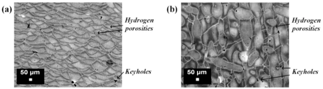
Porosity A compromise between the process parameters and scan
strategies can produce parts with a density of 99.8% [49]
Microstructure, high cycle fatigue, fracture
High fatigue resistance.
[85] The combination of 300◦C platform heating and
peak-hardening (T6) increases the fatigue resistance and neutralizes the differences in fatigue life for the 0◦, 45◦and
90◦directions
Heat treatment
The tensile strength decreases from 434.25±10.7 MPa for the as-built samples to 168.11±2.4 MPa, while the elongation at break increases remarkably from 5.3%±0.22% to 23.7%±
0.84% when the as-built sample is solution-treated at 550◦C for 2 h.
[87]
Precipitation hardening
The duration of the SHT (Solution Heat Treatment) influences the ageing response. A fine microstructure requires a longer
SHT to stabilize the microstructure and enhance the mechanical response, with and without ageing.
[89]
Phase analysis, microstructure characterization
A certain amount of Si dissolved in the Al matrix to form cellular-dendriticα-Al phase (cells of about 500 nm). An Mg2Si dispersoid hardening phase formed during the
SLM process. The network features along the boundary of the Al phase were identified to be a eutectic Al/Si phase. Very
fine grainy features of a nanometric scale were observed within this phase, with dimensions of less than 5 nm.
[90]
Microstructure, heat treatments, hardness, and tensile properties
A fine microstructure with submicron-sized cells
[80,93] High hardness, Yield, and Ultimate tensile strength
Effects of T2, T4, and T6 heat treatments
Corrosion resistance
Preferential dissolution ofα-Al at the border of the laser scan tracks
[81,83,84] Modification of the surface, by means of shot peening or
polishing, increases the pitting potential and reduces the corrosion rate
Figure 7. Optical micrographs of an AlSi10Mg alloy microstructure produced by means of casting (process,) at (a) low and (b) high magnifications: the white particles are composed of a α primary phase, while the matrix is composed of a eutectic α + Si phase (from the authors’ own unpublished work).
Figure 8. Optical micrographs of AlSi10Mg samples produced by means of Direct Metal Laser
Sintering (DMLS) using a unidirectional scanning strategy (along the x axis). This strategy produces parallel scan tracks inside the material, and melt pools with an almost half cylindrical shape can be detected in a cross section parallel to the zy plane.
Figure 9. Optical micrographs of AlSi10Mg samples obtained by means of DMLS, built using a rotated
scanning strategy (67° of rotation between subsequent layers), at different magnifications: (a,b) describe a vertical section of the part along the building direction (z axis), while (c,d) show the section parallel to the building plane (xy-plane).
Figure 7.Optical micrographs of an AlSi10Mg alloy microstructure produced by means of casting (process,) at (a) low and (b) high magnifications: the white particles are composed of aαprimary phase, while the matrix is composed of a eutecticα+ Si phase (from the authors’ own unpublished work).
Figure 7. Optical micrographs of an AlSi10Mg alloy microstructure produced by means of casting
(process,) at (a) low and (b) high magnifications: the white particles are composed of a α primary phase, while the matrix is composed of a eutectic α + Si phase (from the authors’ own unpublished work).
Figure 8. Optical micrographs of AlSi10Mg samples produced by means of Direct Metal Laser
Sintering (DMLS) using a unidirectional scanning strategy (along the x axis). This strategy produces parallel scan tracks inside the material, and melt pools with an almost half cylindrical shape can be detected in a cross section parallel to the zy plane.
Figure 9. Optical micrographs of AlSi10Mg samples obtained by means of DMLS, built using a rotated
scanning strategy (67° of rotation between subsequent layers), at different magnifications: (a,b) describe a vertical section of the part along the building direction (z axis), while (c,d) show the section parallel to the building plane (xy-plane).
Figure 8.Optical micrographs of AlSi10Mg samples produced by means of Direct Metal Laser Sintering (DMLS) using a unidirectional scanning strategy (along thexaxis). This strategy produces parallel scan tracks inside the material, and melt pools with an almost half cylindrical shape can be detected in a cross section parallel to thezyplane.
Materials 2017, 10, 76 11 of 23
Figure 7. Optical micrographs of an AlSi10Mg alloy microstructure produced by means of casting
(process,) at (a) low and (b) high magnifications: the white particles are composed of a α primary phase, while the matrix is composed of a eutectic α + Si phase (from the authors’ own unpublished work).
Figure 8. Optical micrographs of AlSi10Mg samples produced by means of Direct Metal Laser
Sintering (DMLS) using a unidirectional scanning strategy (along the x axis). This strategy produces parallel scan tracks inside the material, and melt pools with an almost half cylindrical shape can be detected in a cross section parallel to the zy plane.
Figure 9. Optical micrographs of AlSi10Mg samples obtained by means of DMLS, built using a rotated
scanning strategy (67° of rotation between subsequent layers), at different magnifications: (a,b) describe a vertical section of the part along the building direction (z axis), while (c,d) show the section parallel to the building plane (xy-plane).
Figure 9.Optical micrographs of AlSi10Mg samples obtained by means of DMLS, built using a rotated scanning strategy (67◦of rotation between subsequent layers), at different magnifications: (a,b) describe a vertical section of the part along the building direction (zaxis); while (c,d) show the section parallel to the building plane (xy-plane).
Materials2017,10, 76 12 of 23
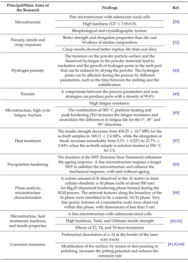
Another two important aspects involved in the melting process are directional cooling and rapid solidification, both of which have a profound influence on the microstructure of SLM parts. Manfredi et al. [80,93] investigated the AlSi10Mg microstructure, considering high magnifications, as illustrated in the FESEM micrograph of Figure10. The area labelled as 2 and 3 corresponds to the heat affected zone of the adjacent melt pools: what is worth noting is the fine cellular-dendritic structure inside the melt pool (area 1), and the different size of the same structures due to thermal gradients (area 4).
Materials 2017, 10, 76 12 of 23
Another two important aspects involved in the melting process are directional cooling and rapid solidification, both of which have a profound influence on the microstructure of SLM parts. Manfredi et al. [80,93] investigated the AlSi10Mg microstructure, considering high magnifications, as illustrated in the FESEM micrograph of Figure 10. The area labelled as 2 and 3 corresponds to the heat affected zone of the adjacent melt pools: what is worth noting is the fine cellular-dendritic structure inside the melt pool (area 1), and the different size of the same structures due to thermal gradients (area 4).
Figure 10. FESEM image of an AlSi10Mg alloy produced by means of the DMLS process in an as-built
condition after etching with a Keller reagent: it is possible to observe the different sizes of the cellular-dendritic structures.
As described by Rosenthal et al. [88], the solidification in the SLM processing of an AlSi10Mg alloy depends on the thermal gradient (G) in the melt pool and on the growth rate (R). The growth rate could be modulated by changing the scanning speed and the angle among the direction of laser scan track and the growth direction of the solidified material. Lowering the R value at constant G values contributed to obtaining a stable planar consolidation front, while an increase in the growth rate induced the formation of cellular, and finally dendrite solidification morphologies. Multiplying G by R gives the cooling rate of the system: the higher the product, the finer the microstructure. Both the thermal gradient and the growth rate are at a maximum in the middle of the melt pool, and decrease slightly going towards the border: the growth rate reaches a zero value at the corner of the laser scan, where the laser path is perpendicular to the heat transfer [20]. As a consequence of modifying the G and R values, the fineness of the grains also varies.
Another effect of the directional solidification in the melt pool is the formation of a crystallographic texture inside the material. Thijs et al. [20] investigated the overall texture of AlSi10Mg parts produced by means of SLM, and the effects of different scanning strategies on the parts. It was evinced that when the cellular solidification mode was active, the preferential growth direction of the cells was along the 〈100〉 crystal direction, going towards the centreline of the melt pool. The thus obtained face centered cubic aluminum cells are decorated with a diamond-like silicon phase. This fine distribution leads to a high hardness of the SLM parts, of about 127 Hv0.5. Moreover, the fineness of the cells is seen to change from below 0.7 μm, at the melt pool border, to 0.4 μm in the middle of the scan track. Furthermore, on the basis of this study, it could be stated that a more anisotropic or isotropic part can be obtained according to which scanning strategy is applied.
In conventional manufacturing, the AlSi10Mg alloy is commonly strengthened through precipitation hardening [22], which consists of a solution heat treatment followed by quenching and artificial ageing. Adopting such a heat treatment on SLM materials modifies the microstructure to a
Figure 10. FESEM image of an AlSi10Mg alloy produced by means of the DMLS process in an as-built condition after etching with a Keller reagent: it is possible to observe the different sizes of the cellular-dendritic structures.
As described by Rosenthal et al. [88], the solidification in the SLM processing of an AlSi10Mg alloy depends on the thermal gradient (G) in the melt pool and on the growth rate (R). The growth rate could be modulated by changing the scanning speed and the angle among the direction of laser scan track and the growth direction of the solidified material. Lowering the R value at constant G values contributed to obtaining a stable planar consolidation front, while an increase in the growth rate induced the formation of cellular, and finally dendrite solidification morphologies. Multiplying G by R gives the cooling rate of the system: the higher the product, the finer the microstructure. Both the thermal gradient and the growth rate are at a maximum in the middle of the melt pool, and decrease slightly going towards the border: the growth rate reaches a zero value at the corner of the laser scan, where the laser path is perpendicular to the heat transfer [20]. As a consequence of modifying the G and R values, the fineness of the grains also varies.
Another effect of the directional solidification in the melt pool is the formation of a crystallographic texture inside the material. Thijs et al. [20] investigated the overall texture of AlSi10Mg parts produced by means of SLM, and the effects of different scanning strategies on the parts. It was evinced that when the cellular solidification mode was active, the preferential growth direction of the cells was along theh100icrystal direction, going towards the centreline of the melt pool. The thus obtained face centered cubic aluminum cells are decorated with a diamond-like silicon phase. This fine distribution leads to a high hardness of the SLM parts, of about 127 Hv0.5. Moreover, the fineness of the cells is seen to change from below 0.7µm, at the melt pool border, to 0.4µm in the middle of the scan track. Furthermore, on the basis of this study, it could be stated that a more anisotropic or isotropic part can be obtained according to which scanning strategy is applied.
In conventional manufacturing, the AlSi10Mg alloy is commonly strengthened through precipitation hardening [22], which consists of a solution heat treatment followed by quenching
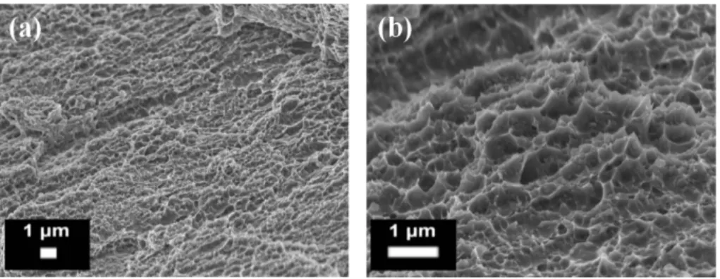
and artificial ageing. Adopting such a heat treatment on SLM materials modifies the microstructure to a great extent, as pointed out by Brandl et al. [85]. In their study, they showed how the as-built microstructure, constituted by cellularα-Al dendrites and interdendritic Si particles, was modified by a heat treatment, and that eutectic globular Si particles, homogeneously distributed inside theα-Al matrix, were obtained: all the microstructural differences, such as different grain size, heat affected zone, and melt pools, were eliminated. Li et al. [87] investigated the effect of different treatments, and highlighted how the microstructure became coarser when the solution temperature was increased from 450 to 550◦C, and in particular after artificial ageing (at 180◦C for 12 h). It was observed that when as-built SLM AlSi10Mg specimens were solution heat treated at 450◦C for 2 h, the mean Si particle size was less than 1µm. When a 550◦C solution temperature was adopted, it rose to 4µm, instead, when a subsequent artificial ageing was applied, the particles again became coarser, reaching a mean dimension of 5µm. During the solution heat treatment and artificial ageing, the supersaturated Al phase rejected Si, which started to agglomerate in small particles. Aboulkhair et al. [89] recently established to what extent the SLM microstructure requires a different solution treatment duration from that of the casting materials. The fine microstructure of SLM AlSi10Mg required longer times than the cast one to be fully stabilized and homogenized: the precipitation behavior was completely different in a coarse microstructure from that of an ultrafine grained one.
The process and the adopted scanning strategy can deeply modify the microstructure and texture of the material [20,88], and they also have an important influence on the consolidation of the parts: the complexity of the melting and creation of defects inside the material has required a great deal of attention from both industry and research to study the correct process parameter window for SLM. One of the main aspects so far investigated is the extent of the porosity inside SLM materials, as this is a detrimental feature as far as the mechanical properties and fatigue life of aerospace components are concerned, since it compromises structural integrity and can favor premature and unexpected structural failure of the parts [61]. Kempen et al. [59] conducted an in-depth investigation of the correct choice of laser power and scanning speed with the aim of obtaining fully dense materials. Varying the laser power from 170 to 200 W and the scanning speed between 200 and 1400 mm/s, they were able to investigate the melting behavior of the powders adopting a laser energy per unit length approach. From the results, they established a process window in which it was possible to obtain 99% dense materials, while keeping the other process parameters fixed. The correct amount of energy in fact made it possible to avoid the entrapment of gases and an insufficient overlapping of the tracks, and consequently reduced the amount of porosity inside the material.
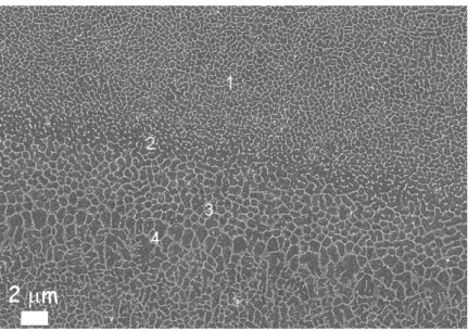
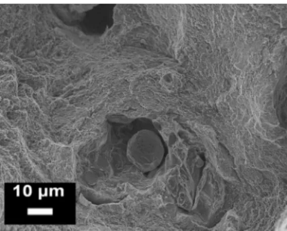
Considering hydrogen porosity, Weingarten et al. [44] investigated the formation of these pores in detail (Figure11) during AlSi10Mg processing. The effect of a pre-drying treatment of the powder on the densification mechanism and porosity formation was studied, and it was established that a heat treatment of the powder bed at 200◦C, before the melting process, led to a reduction in hydrogen porosity of approximately 50%. The drying treatment in fact reduced the amount of moisture on the powder surface, an aspect that is related directly to the porosity formation during melting [43,45].
Materials 2017, 10, 76 13 of 23
great extent, as pointed out by Brandl et al. [85]. In their study, they showed how the as-built microstructure, constituted by cellular α-Al dendrites and interdendritic Si particles, was modified by a heat treatment, and that eutectic globular Si particles, homogeneously distributed inside the α -Al matrix, were obtained: all the microstructural differences, such as different grain size, heat affected zone, and melt pools, were eliminated. Li et al. [87] investigated the effect of different treatments, and highlighted how the microstructure became coarser when the solution temperature was increased from 450 to 550 °C, and in particular after artificial ageing (at 180 °C for 12 h). It was observed that when as-built SLM AlSi10Mg specimens were solution heat treated at 450 °C for 2 h, the mean Si particle size was less than 1 μm. When a 550 °C solution temperature was adopted, it rose to 4 μm, instead, when a subsequent artificial ageing was applied, the particles again became coarser, reaching a mean dimension of 5 μm. During the solution heat treatment and artificial ageing, the supersaturated Al phase rejected Si, which started to agglomerate in small particles. Aboulkhair et al. [89] recently established to what extent the SLM microstructure requires a different solution treatment duration from that of the casting materials. The fine microstructure of SLM AlSi10Mg required longer times than the cast one to be fully stabilized and homogenized: the precipitation behavior was completely different in a coarse microstructure from that of an ultrafine grained one.
The process and the adopted scanning strategy can deeply modify the microstructure and texture of the material [20,88], and they also have an important influence on the consolidation of the parts: the complexity of the melting and creation of defects inside the material has required a great deal of attention from both industry and research to study the correct process parameter window for SLM. One of the main aspects so far investigated is the extent of the porosity inside SLM materials, as this is a detrimental feature as far as the mechanical properties and fatigue life of aerospace components are concerned, since it compromises structural integrity and can favor premature and unexpected structural failure of the parts [61]. Kempen et al. [59] conducted an in-depth investigation of the correct choice of laser power and scanning speed with the aim of obtaining fully dense materials. Varying the laser power from 170 to 200 W and the scanning speed between 200 and 1400 mm/s, they were able to investigate the melting behavior of the powders adopting a laser energy per unit length approach. From the results, they established a process window in which it was possible to obtain 99% dense materials, while keeping the other process parameters fixed. The correct amount of energy in fact made it possible to avoid the entrapment of gases and an insufficient overlapping of the tracks, and consequently reduced the amount of porosity inside the material.
Considering hydrogen porosity, Weingarten et al. [44] investigated the formation of these pores in detail (Figure 11) during AlSi10Mg processing. The effect of a pre-drying treatment of the powder on the densification mechanism and porosity formation was studied, and it was established that a heat treatment of the powder bed at 200 °C, before the melting process, led to a reduction in hydrogen porosity of approximately 50%. The drying treatment in fact reduced the amount of moisture on the powder surface, an aspect that is related directly to the porosity formation during melting [43,45].
Figure 11. Optical images of an AlSi10Mg microstructure after Keller’s etching: (a) vertical section;
(b) horizontal section. The metallurgical pores (hydrogen porosities) and the keyhole defects are indicated in the micrographs.
In another study, Aboulkhair et al. [49] investigated the effects of different process parameters on the formation of defects inside the microstructure of AlSi10Mg samples. The metallurgical pores
Figure 11.Optical images of an AlSi10Mg microstructure after Keller’s etching: (a) vertical section; (b) horizontal section. The metallurgical pores (hydrogen porosities) and the keyhole defects are indicated in the micrographs.