Reorienting MHD Colliding Flows:
A Shock Physics Mechanism for Generating Filaments
Normal to Magnetic Fields
Erica Fogerty
1?, Jonathan Carroll-Nellenback
1, Adam Frank
1, Fabian Heitsch
2,
Andy Pon
31 206 Bausch & Lomb Hall, Department of Physics & Astronomy, University of Rochester, Rochester, New York, 14627, USA 2 3255 Phillips Hall, Department of Physics & Astronomy, University of North Carolina, Chapel Hill, North Carolina, 27599, USA 3 Department of Physics & Astronomy, University of Western Ontario, London, Ontario, N6A 3K7, Canada
Submitted 2016 September
ABSTRACT
We present numerical simulations of reorienting oblique shocks that form in the collision layer between magnetized colliding flows. Reorientation aligns post-shock filaments normal to the background magnetic field. We find that reorientation begins with pressure gradients between the collision region and the ambient medium. This drives a lateral expansion of post-shock gas, which reorients the growing filament from the outside-in (i.e. from the flow/ambient boundary, toward the colliding flows axis). The final structures of our simulations resemble polarization observations of filaments in Taurus and Serpens South, as well as the integral-shaped filament in Orion A. Given the ubiquity of colliding flows in the interstellar medium, shock reorientation may be relevant to the formation of filaments normal to magnetic fields.
Key words: magnetohydrodynamics(MHD) – ISM: kinematics and dynamics – ISM: structure – ISM: clouds – stars: formation
1 INTRODUCTION
Colliding gas flows and filaments are commonly found in star forming regions. Converging flows have been detected surrounding molecular gas in Taurus (Ballesteros-Paredes, Hartmann & V´azquez-Semadeni 1999), the Sh 156 and NGC 7538 molecular clouds (Brunt 2003), and star forming fila-ments in Serpens South (Kirk et al. 2013; Fern´andez-L´opez et al. 2014). On the largest scales, they can arise from su-pernovae, energetic winds surrounding young stars and clus-ters, and the motion of galactic spiral arms through the intragalactic medium. On smaller scales, converging flows can take the form of accretion flows. Similarly, filaments are ubiquitous in star forming regions. Many have been found to contain young protostellar cores (Andr´e et al. 2010; Arzou-manian et al. 2011; Polychroni 2012; Lee et al. 2014), and thus, are considered some of the earliest structures of star formation.
Observations of filaments indicate that they might be tied to colliding flows. Measurements of velocity gradients perpendicular to filaments (Kirk et al. 2013; Fern´
andez-? E-mail:[email protected]
L´opez et al. 2014) have been interpreted as arising from in-fall onto the filaments (i.e. converging accretion flows). Dust polarization maps show that the plane-of-sky component of the surrounding magnetic field also lies perpendicular to fil-aments (Goodman et al. 1992; Chapman et al. 2011; Planck Collaboration et al. 2016). That both of these quantities also are aligned with low density ‘striations’ suggests that gas is converging onto filaments, along magnetic fields (Palmeirim et al. 2013). Interestingly, fluid motions seem to change di-rectioninside of filaments, so that the gas flowsalong fila-ments, internally (Kirk et al. 2013; Fern´andez-L´opez et al. 2014). Given that the uncertainty of dust polarization mea-surements increases with density (Goodman et al. 1992), the field might actually change direction to become parallel in-side of filaments as well. Indeed, if the internal fielddid not become more or less parallel to the filament, external field lines would be bent away from normal due to drag between internal fluid motions and the field (as shown in panel 4A, Fig. 1).
The gas motions and accompanying magnetic field ge-ometry associated with filaments have primarily been at-tributed to magneto-gravitational instability. In this concep-tualization, an over-dense region within a molecular cloud
first becomes Jeans unstable (panel 1A, Fig. 1). Collapse is triggered and proceedsalong magnetic field lines, as the gas is not yet magnetically supercritical (panel 2A). Once enough mass accumulates for the region to become mag-netically supercritical, gas can begin to fall in perpendicu-lar to the field, as well. For magnetically supercritical fil-aments, this means collapse would then proceedalong the filament (panel 3A; Pon, Johnstone & Heitsch (2011); Pon et al. (2012); Toal´a, V´azquez-Semadeni & G´omez (2012)). At this point, the field would become distorted as it is dragged down into the collapsing gas (panel 4A). That the magnetic field strength increases with density in collapsed gas (i.e. B∝n, n >1000cm−3; Troland & Heiles (1986); Crutcher (1999); Crutcher et al. (2010); Tritsis et al. (2015)) has com-monly been cited as evidence for this scenario.
An alternative explanation that does not require be-ginning with a Jeans unstable mass is the reorientation of oblique magnetized shocks, which is the focus of the present paper. This model begins with the collision of marginally supersonic gas along magnetic field lines (i.e. the path of least resistance). In the most general case, where the flows meet at a non-normal interface, it has recently been found that the central shock layer readjusts so that it becomes nor-mal to the upstream field (and oncoming flows). This effect, which has been reported by K¨ortgen & Banerjee (2015) and Fogerty et al. (2016), is also consistent with observed fila-ment gas motions and field morphology (i.e. perpendicular external fluid motions and field lines, as well as parallel in-ternal fluid motions). Moreover, distortion of field lines by passage through colliding flows shocks (cf. Chen & Ostriker (2014)) also produces a power law relationship of the mag-netic field strength with density (Heitsch et al. 2007; Hen-nebelle et al. 2008; Banerjee et al. 2009), consistent with the observations described above.
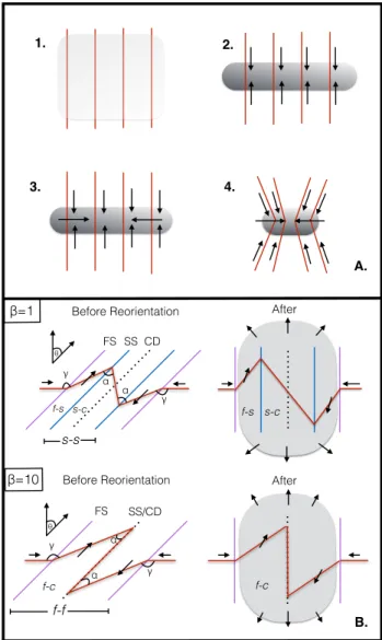
To orient the reader, a schematic of the reorientation process is illustrated in the bottom panel of Figure 1. For the moderately magnetized cases of this paper (those runs that have aβ= 1, whereβis the ratio of the thermal to mag-netic pressure), supersonic inflows that meet at an oblique angle (θ) generate both an MHD fast shock (F S) and slow shock (SS) on either side of a contact discontinuity (CD; Fig. 1B, top/left). Between theF S andSS(region f−s), gas that moves parallel to the shock front (note the flow direction is given by the black arrows) drags magnetic field linesaway from the shock normal, whereas in regions−s, field lines bendtowardthe normal as they connect across the CD. Over time, the entire post-shock region reorients (right panel), where the grey-shaded region represents the growing filament. As we will show, this process depends heavily on the lateral ejection of material away from the growing fila-ment into the ambient medium (represented by the outward directed arrows, right hand column), which occurs due to pressure gradients between the post-shock gas and the am-bient medium. The result is similar when the magnetic field is weakened (β= 10, Fig. 1B, bottom), notwithstanding the slight changes to the shock structure. That is, reorientation produces a post-shock flow and field that has parallel com-ponents to the filament, internally (in regionsf−sandf−c, in the β= 1 andβ = 10 cases, respectively), and perpen-dicular components, externally. This MHD shock process is the topic of the present paper.
We present a suite of 2D magnetized, colliding flows
1. 2.
3. 4.
FS SS CD
f-s s-c FS SS/CD α α γ γ f-c B. A. β=1 β=10 f-s s-c s-s f-c f-f
Before Reorientation After
Before Reorientation After
α γ α γ θ θ
Figure 1.Mechanisms for generating filaments normal to mag-netic field lines.Top Panel.Magneto-gravitational collapse. Jeans unstable gas will initially collapse along field lines (1-2). Once enough mass accumulates in the resultant filament, mass can flow along the filament and drag magnetic field lines inward (3-4). Bot-tom Panel.Reorientation of magnetized oblique shocks. Upper-case letters denote wave modes, and lowerUpper-case letters give regions (see text). Flow direction is given by the black arrows, and a rep-resentative magnetic field line is shown in red. The left and right panels give the initial and reoriented structures, respectively. The top and bottom rows give the moderate (β = 1) and weak field (β= 10) cases of this paper. The grey shaded region represents the growing filament.
simulations that test the effects of varying the magnetic field strength and the inclination angle of the collision in-terface on reorientation. We find that reorientation is pos-sible in all but the strongest magnetic field cases, resulting in post-shock filaments1 that approach a normal
tion with respect to the upstream velocity and magnetic field. In addition, we show that fluid motions are highly parallel to the filament within the shock bounded gas, and that oblique, magnetized colliding flows naturally assume an s-shaped structure, reminiscent of the integral-shaped fila-ment (Bally et al. 1987; Johnstone & Bally 1999). Our paper is organized as follows. We begin with a description of our numerical methods and model (Section 2). We then discuss 1D shock solutions relevant to our work (Section 3) and our key results (Section 4). We finish with a discussion of our findings in Section 5 and present a resolution study of our results in the appendix.
2 METHODS
Our simulations were performed using AstroBEAR2 (Cun-ningham et al. 2009; Carroll-Nellenback et al. 2013). As-troBEAR is a massively parallelized, adaptive mesh refine-ment code designed for astrophysical contexts. The numeri-cal code solves the conservative equations of hydrodynamics and magnetohydrodynamics, and includes a wide-range of multiphysics solvers. A sampling of these solvers include self-gravity, sink particles, various heating and cooling processes, magnetic resistivity, and radiative transfer. The AstroBEAR code is well tested (see, for example, Poludnenko, Frank & Blackman (2002); Cunningham et al. (2009); Kaminski et al. (2014)), under active development, and fully documented by the University of Rochester’s computational astrophysics group.
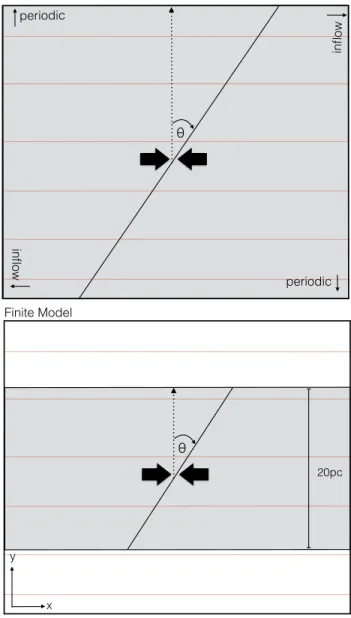
The present suite of simulations consists of two sets of runs. The first was a pair of shock models that reviewed the wave solutions acrossinfinitehydrodynamic (hydro) and magnetohydrodynamic oblique shocks, using an exact Rie-mann solver and HLLD solver, respectively. The shocks were generated by marginally supersonic flows (M = 1.5, where M is the mach number) that collided at an oblique inter-face, following Haig et al. (2012) and Fogerty et al. (2016). These flows were injected along the x boundaries of a 2D grid so that they completely filled the domain (Fig. 2, top panel). Boundary conditions inywere set to periodic. The obliquity of the collision interface was given by the inclina-tion angle, θ, and was fixed at θ = 30◦. While these runs were performed on a 2D mesh, the fluid variables varied only along the x−dimension. Thus, these runs provide the wave solutions across 1D oblique shocks. The second set of runs was a parameter study of 2Dfinitemagnetized colliding flows. In these runs, the flows were embedded in a stationary ambient medium of the same density and pressure (Fig. 2, bottom panel). The flows were again marginally supersonic (M = 1.5), and collided at an oblique interface, given by the inclination angle θ. The inclination angle of the finite runs varied betweenθ= 30◦and 60◦. The complete suite of simulations is given in Table 1.
Self-gravity was not included in the present suite of simulations. Consequently, the simulations neglected gravi-tational collapse along filaments. The runs instead tracked the formation and early evolution of filaments, while illus-trating the basic mechanism of reorientation. Cooling was
2 https://astrobear.pas.rochester.edu
θ
20pc
periodic
Finite Model
x y
inflow
inflow
periodic
θ
Infinite Model
Figure 2. Model diagrams. Top panel. Setup for the infinite cases. Incoming flows meet at an effectively infinite oblique shock, defined by the angleθ. Boundary conditions of the different box sides are labeled. Magnetic field lines are represented by the red lines, and the flow is uniform everywhere along the collision in-terface, in the direction given by the thick black arrows.Bottom panel. Setup for the finite cases. The colliding flows are now em-bedded in a stationary ambient medium of the same density and pressure. The flows are 20pcin diameter and collide at an oblique collision interface, given byθ. The uniform magnetic field is again given by the red lines, and runs everywhere parallel to the flows.
included in all of the finite colliding flows runs, following a modified Inoue & Inutsuka (2008) cooling curve. The mod-ification allowed the gas to cool toT = 10K, appropriate for ISM conditions (Ryan & Heitsch, in prep). The infinite cases did not include cooling, but instead used an adiabatic equation of state withγ= 5/3.
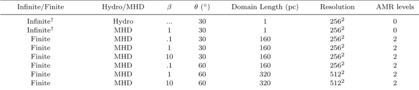
Table 1.Suite of simulations.
Infinite/Finite Hydro/MHD β θ(◦) Domain Length (pc) Resolution AMR levels
Infinite† Hydro ... 30 1 2562 0
Infinite† MHD 1 30 1 2562 0
Finite MHD .1 30 160 2562 2
Finite MHD 1 30 160 2562 2
Finite MHD 10 30 160 2562 2
Finite MHD .1 60 160 2562 2
Finite MHD 1 60 320 5122 2
Finite MHD 10 60 320 5122 2
†Did not include cooling
thermal equilibrium (for those runs that included cooling). The speed of each inflow wasv= 11km s−1. For those runs that included a magnetic field (cf. Table 1), the field was uniform throughout the simulation domain and ran parallel to the flows. The strength of the field was set byβ. In the 1D MHD case,β= 1. For the finite colliding flows runs,β ranged between β = 10−.1. This is equivalent to a field strength ofB= 1.6−16µG, in line with current measure-ments of the global mean field of the ISM (B ≈1−10µG, Beck (2001); Heiles & Troland (2005)).
The infinite colliding flows runs had periodic boundary conditions in y and inflow boundary conditions inx. The length of the square 2D domain was 1pcon a side. The mesh was a fixed-grid at a resolution of 2562and had a cell size of 4x=.0039pc. For the finite colliding flows runs, the size of the square domain was chosen to be large enough so that no gas or magnetic field lines left the box over the course of the simulation (cf. Table 1). However, the effective resolution was held constant at a finest cell size of4xmin=.15625pc. Boundary conditions were set to inflow where the flows were injected, and extrapolating everywhere else. The radius of the finite colliding flows wasr= 10pc. The final simulation time for the finite runs was tsim = 12 M yr. The infinite cases were shorter attsim= 1M yr, the time it took for the shocks to reach the edge of the simulation domain.
3 INFINITE ADIABATIC OBLIQUE SHOCKS
Before we present the simulations of reorienting MHD col-liding flows, we briefly discuss the hydro and MHD shocks that are generated by infinite, adiabatic colliding flows. The results of this section provide a framework for evaluating the shocks that are formed between finite, cooling colliding flows. Given this section is just a review of 1D oblique shock solutions, the reader can feel free to jump ahead to our main results in Section 4.
3.1 Hydro Case
The hydro Riemann problem relevant to the present paper consists of a constant density and pressure fluid that is sepa-rated by a discontinuous jump in velocity. In particular, the velocity field converges on the central Riemann interface at an oblique incidence. Note, the inclination angle of the in-terface for both the infinite hydro and MHD run (discussed
below) was chosen to beθ= 30◦, to match the finiteθ= 30◦ runs of Section 4.
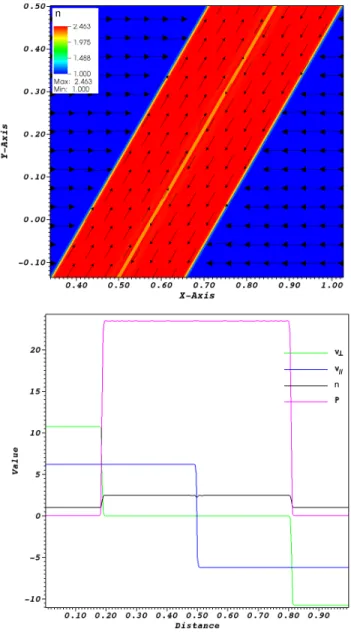
As can be seen in Figure 3, this Riemann problem gen-erates two oblique shocks that are separated by a contact discontinuity. In addition to the characteristic density in-crease across each shock front, the top panel of Figure 3 shows that velocity vectors bend away from the shock nor-mal across each shock. This occurs because only perpendic-ular components of upstream velocity vectors (v⊥) change across shocks. This leads to v⊥ → 0 in the downstream gas. Note, ifv⊥6= 0 in the post-shock gas, additional waves would be generated behind the shocks, which would violate the three-wave solution family of hydrodynamic Riemann problems. Thus, post-shock gas flowsexactlyparallel to each shock front. In other words,oblique shocks generate shear. The various fluid variables across the wave modes are given in the bottom panel of Figure 3.
3.2 MHD Case
//
n
n
n
Figure 3. The fluid variables across hydrodynamic, oblique shocks. Top panel shows number density of the infinite hydro-dynamic Riemann problem described in text. Velocity vectors are overlaid and scaled by magnitude. Bottom panel gives the various fluid variables across the waves. Perpendicular and par-allel components of velocity (v⊥ and v//, respectively) are in
units ofkm s−1, number density incm−3, and pressure (P) in
K cm−3. Note, pressure has been scaled to fit on the y−axis, whereP= (P−4931)×10−3.
4 FINITE OBLIQUE SHOCKS, WITH COOLING
We now turn to our finite magnetized colliding flows runs to address the issue of reorientation of oblique shocks. Note, this section differs from the last in that now the flows are embedded in a stationary ambient medium. We begin by discussing the effects of varying β and θ on the morphol-ogy of reoriented flows. We then move on to discussing the temporal evolution of each of the cases, again focusing on morphological changes over the course of the simulations.
n
n
n
Figure 4.The fluid variables across MHD, oblique shocks.Top panelshows number density of the infinite MHD Riemann prob-lem described in text. Field lines increase in strength from white to red, and velocity vectors are scaled by magnitude. Bottom panel gives the fluid variables across the waves. Units are the same as in Figure 3, with the addition of the perpendicular and parallel magnetic field components (B⊥andB//, respectively),
given inµG.
4.1 The Effects of Varyingβ and θ on Reorientation
Plots of number density show that whenβ=.1, for inclina-tion angles of eitherθ= 30◦or 60◦, magnetic field lines are strong enough to resist ejection of material from the collision region (Fig. 5, top panel). Any material that does manage to escape the collision region travels parallel to the colliding flows, along the field lines, and is deposited in what we call the ‘trailing arms’ of the filament – a prominent feature of finite, oblique, magnetized colliding flows (see red circles in Fig. 5, top-left panel). Indeed, the field is so strong in these cases that a post-shock shear flow is also inhibited, as the field effectively resists motion perpendicular to it. Instead, post-shock material is delivered directly onto the growing filament, where it continues to collect, cool, and compress over the course of the simulation. This results in a smooth and flat filament, as turbulent sub-structure (induced from the thermal instability, e.g.) is also effectively inhibited.
The behavior begins to change as the magnetic field is weakened. When β is increased to 1, theθ = 30◦ case ex-hibits a large-scale reorientation. This is illustrated in Figure 5 (middle row, left panel), where we see an initially inclined filament has reoriented to become more or less normal to the oncoming flows. As in the infinite version of this case, an outer shock layer forms that diverts incoming flows ei-ther diagonally ‘up’ or ‘down’, depending on the upstream interface orientation (cf. Section 3.2). However, across the second, inner shock (region s−s), gas is falling onto the long axis of the filament, along magnetic field lines. This is in contrast to the infinite case, where fluid motions were ab-sent in this region, and thus, these motions are arising from cooling. The result is the formation of a post-shock flow that has parallel components to the filament in both the f−s ands−cregions.
Near the top and bottom of the filament (i.e. near the flow/ambient boundary), and across the CD, the velocity vectors become aligned so that they are pointing alongy, out into the ambient medium. That is, the flow switches from being a shear flow across theF S, to being directed outwards into the ambient medium in the entire f−f region (near the flow/ambient boundary). This is due to pressure gradi-ents between the collision region and the ambient medium. The ejection of material from the over-pressurized collision region into the ambient medium drives arcs in the magnetic field, whose tension impedes further lateral flow and traps the ejected gas (see Fogerty et al. (2016) for an analytical description of this process). This trapped gas travels along the magnetic field line arcs, as shown by the corresponding velocity vectors in Figure 5, where it collects in the trailing arms. This three-step process, namely, 1) post-shock ejec-tion from the collision region into the ambient medium, 2) the bending of the magnetic field lines into arcs, and 3) the redirection of incoming flows along the arcs to collect in the trailing arms of the filament, produces an ‘s-shaped’ filamentary structure.
As the inclination angle is steepened to 60◦ for the β = 1 case, the same trends develop. Namely, material is deflected away from the shock normal across theF S, ejected from the collision region into the ambient medium, and an s-shaped filament forms with a similar degree of reorienta-tion by t= 12 M yr. While the higher obliquity shocks of this run produce weaker post-shock compression and thus a widerf−s region, changing the inclination angle does not
appear to drastically alter the degree of reorientation for the moderate field,β= 1 cases.
As the field is weakened further in the β = 10 runs, the 30◦ case reorients to a similar degree, but reorienta-tion is enhanced in the 60◦ case (Fig. 5, bottom row). We also see that slightly different filamentary structures form, as there are no longer slow shocks present in the filaments. This means that byβ= 10, the shock solutions have effec-tively approached the 1D hydro solutions (away from the flow/ambient boundary), as they must, in the limit of weak magnetic field. Furthermore, there are no longer s−s re-gions (marked by a stagnate velocity field), where material can expand away from the collision region due to pressure gradients alone. Instead, incoming gas is quickly shunted away from the collision region as it passes through the sin-gle oblique shock on either side of theCD. As this material leaves the collision region, it drags magnetic field lines away with it. As the plots show, the weaker field is dragged to further distances, and thus the trailing arms extend farther away into the ambient medium from the main filament body (beyond the plot boundaries).
4.2 Temporal Evolution of the Flows
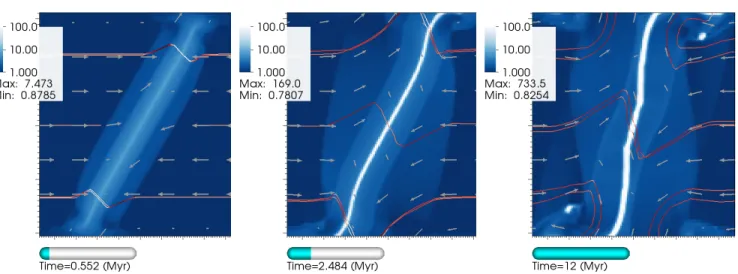
We now turn to the temporal evolution of the flows. We will again be focusing on density plots with overlaid velocity vec-tors and magnetic field lines, beginning with the stronger field (β = 1) cases. Figure 6 shows the evolution of the β = 1, θ = 30◦ case. As can be seen in thet =.55 M yr panel, the bulk properties of the flow are similar to the in-finite MHD case (Section 3.2), at early times. That is, a shear flow is established across the outer,F S, and negligi-ble fluid motions occur inside of regions−s. Over time, post-shock cooling triggers inflow along the field lines onto theCD of the forming filament (t= 2.5M yr). Addition-ally, this time panel shows that the fast shocks stall (near the top flow/ambient boundary for the rightF S, and near the bottom for the leftF S). This is due to a decrease in thermal pressure support behind the shocks as material es-capes into the lower pressure ambient medium. The result of these stalled shock fronts is the reorientation of the outer shock layers, as those regions that are not stalled continue to propagate away from the collision region. This leads to the outer shock layers becoming normal to the oncoming flows. As can be seen in the figure (and even better in the animations online3), reorientation of the inner shock layer (i.e. region s−s) also begins with the lateral ejection of material from the collision region. That is, reorientation oc-curs from theoutside-in – beginning near the flow/ambient boundary and moving toward the colliding flows axis by t= 12M yr. This occurs as material is delivered along the ‘z-shaped’ magnetic field lines near the colliding-flows axis nearly vertically onto the long axis of the filament. When the inclination angle is steepened to θ = 60◦ for the same value ofβ = 1, the evolution is qualitatively similar (Fig. 7).
As the field is weakened toβ= 10, the largest difference
3 See the following youtube
β
=0.1,
θ
=30
β
=1,
θ
=30
β
=10,
θ
=30
β
=0.1,
θ
=60
β
=1,
θ
=60
β
=10,
θ
=60
θ
initθ
initθ
initθ
initθ
initθ
initFigure 5.Density plots of the six finite colliding flows runs, with overlaid velocity vectors and magnetic field lines. Each plot shows the flows at the final simulation time of 12M yr. The legend gives number density in units ofcm−3. Vectors are scaled by magnitude, and field lines increase in strength from white to dark red. The initial inclination angle of the collision interface is given byθinit. The
Figure 6.Temporal evolution of theβ= 1, θ= 30◦case. All units are the same as in Figure 5.
Figure 7.Temporal evolution of theβ= 1, θ= 60◦case. All units are the same as in Figure 5.
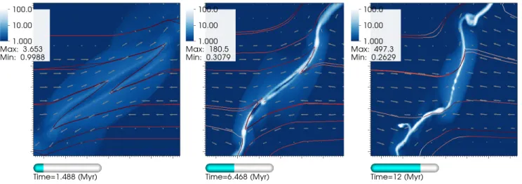
Figure 9.Temporal evolution of theβ= 10, θ= 60◦case. All units are the same as in Figure 5.
that occurs in the evolution is the appearance of a vacated inner region along the filament’s long axis (FLA) as mate-rial preferentially collects around the top and bottom of the filament (i.e. near the flow/ambient boundary), as well as just exterior to the FLA (see Figures 8 and 9, middle pan-els). This arises from the extreme amplification of the field along theCD as field lines are stretched by the shear flow (recall, the color of the field lines increases from white to dark red with increasing field strength). By the last time panel, in both theθ = 30◦and 60◦ cases, gas has success-fully collapsed onto the FLA, and the internal high density regions of the filament have begun to reorient, again from the outside-in. Within the regionf−f, the flow and the field are highly parallel to the filament, and the entire structure (filament+trailing arms) has assumed an s-shaped geometry. While this overall evolution is the same between the two β = 10 cases, the external flow field in the θ = 60◦ case att= 12M yr is unlike any of the other runs. Velocity vectors show that material entering from the left is directed downwards as it approaches the filament, and that material entering from the right is directed upwards. Note, this is the oppositeflow pattern that the oblique shocks establish alone (see earlier time panels), indicating that the flow is traveling along bowed magnetic field lines. Such an asymmetric flow is necessary to generate a torque on the filament. This could explain why the β= 10, θ= 60◦ case reorients more than theβ= 1, θ= 60◦case (see also Fig. 11).
5 DISCUSSION
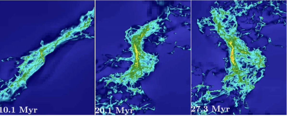
We have presented an MHD shock mechanism capable of re-orienting filaments formed via colliding flows. This process was identified previously in fully 3D simulations of magne-tized colliding flows that included turbulence, self-gravity, cooling, and oblique shocks at the collision interface (Fogerty et al. 2016). In that work, large-scale reorientation of molec-ular gas had occurred for a highly oblique run (Fig. 10). Reorientation of the collision interface of 3D, magnetized, oblique colliding flows was also recently reported by K¨ortgen & Banerjee (2015). By running the simulations in 2D,
with-out gravity, we have shown that the mechanism of reorienta-tion is robust. Moreover, that hydro simulareorienta-tions of oblique colliding flows do not exhibit reorientation (both in 2D, as well as 3D, Haig et al. (2012), Haig & Heitsch, in prep), indi-cates that magnetic fields play a crucial role in the process.
As we have shown, reorientation begins with the lateral ejection of material away from the post-shock collision re-gion between colliding flows. Without magnetic fields, ejecta would continue to push out into the ambient medium until its ram pressure came into balance with the thermal pres-sure of the environment. With magnetic fields, this mate-rial is funneled back down along bowed magnetic field lines, toward the colliding flows surface. This produces what we have called, ‘trailing arms’ of the filament. Additionally, es-caped gas from the collision region into the ambient medium translates into a loss of post-shock pressure support, result-ing in stalled outer shocks. This led to the reorientation of the outer shocks, whichisalso seen in hydro. The difference lies in the reorientation of the densest regions of the filament (i.e. along theCDof the collision region), which doesnot oc-cur without the magnetic field. Instead, the shear flow setup across hydro oblique shocks generates instabilities (i.e. KH modes) along the interface. These instabilities in turn pro-duce a ‘stair-casing’ structure, but not a coherent filament that reorients (Haig et al. 2012). Hennebelle (2013) showed that in order to build a coherent filament in a shear flow, a magnetic field must be present.
Figure 10.Evolution of the 3Dβ= 10, θ= 60◦case, with self-gravity. Image taken from Fogerty et al. (2016). The colors represent column density, and increase from blue to red. See Fogerty et al. (2016) for details.
and this coincided with a large-scale asymmetric flow onto the filament. The mismatch in incoming x-momenta onto the filament can be seen in the right-hand panel of Figure 11, which illustrates the effect for the smaller inclination angle case,β= 10, θ= 30◦. As the figure shows, there is an asymmetric loss of material from the collision region across theCDin the weak field cases (yellow circles), which could lead to a net torque being generated by the bounded flow that remains (red arrows).
Lastly, we have demonstrated that reorientation pro-duces structures that are reminiscent of those found in nearby star-forming regions. Namely, we have shown that under realistic ISM magnetic field strengths, reorientation generates filaments perpendicular to their background mag-netic fields, as well as exhibit velocity motions that switch from being perpendicular externally to parallel internally. These features are consistent with observations of star-forming filaments (Kirk et al. 2013; Palmeirim et al. 2013; Fern´andez-L´opez et al. 2014; Planck Collaboration et al. 2016). Additionally, we have shown that filaments formed via finite, magnetized oblique shocks naturally assume an s-shaped geometry.
6 APPENDIX: RESOLUTION STUDY
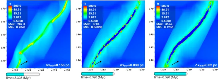
We conducted a short resolution study of the β = 10, θ = 60◦ case, which shows that increasing the resolution to a minimum cell size of 0.02 pc (3 additional AMR lev-els),does not change the reorientation behavior of the MHD oblique shock layer. As Figure 12 shows, however, a cou-ple of differences are present at higher resolution. First, the internal structure of the filament appears to not be fully re-solved in the present paper: a low-density, internal layer of the filament is present at higher resolution (Fig. 12, middle and right panels). Note, this structure is present early-on, at lower resolution (c.f. leftmost panels of Figures 8 & 9). This suggests that numerical diffusion diminishes magnetic pressure in this region in the lower resolution runs, thereby allowing material to cool and condense onto the axis. Indeed, as the resolution increases, the total magnetic energy in the simulations continues to increase as well (fort >2.4M yr,
Fig. 13), as post-shock compressions result in magnetic field amplification.
Second, the small-scale structure that develops in the post-shock flow has not converged at the resolution of the present paper. These results are consistent with Koyama & Inutsuka (2004), who show that thermal instability-induced fragmentation converges (in 1D) only when 1) the Field Length, λF = (κT /ρ2Λ)1/2, where κ is the coefficient of thermal conductivity and Λ is the cooling rate of thermally unstable gas (Field 1965), is resolved by at least 3 zones, and 2) thermal conduction is included in the simulations. Along the collision interface, and away from the flow boundaries, the present suite of finite simulations are effectively 1D (at early times). However, since thermal conduction is ignored in the present work, we expect to see artificial growth of small-scale modes of the TI, seeded by numerical noise on the grid scale. This explains the formation of increasingly smaller-scale clumplets in the post-shock flow with increas-ing resolution.
Taken together, a direct comparison of the simulation results to filaments in the ISM is not possible. However, our intention in this paper was to shed light on a poten-tial MHD shock mechanism associated with oblique collid-ing flows, rather than investigate the detailed characteristics of filaments formed by this mechanism. Moreover, since the present suite of runs are 2D, the detailed structure of the filaments are artificially idealized from the outset (clearly evident when comparing the rightmost panel in Fig. 12 with its 3D counterpart: Fig. 10). The results of this resolution study support that the reorientation mechanism is a large-scale phenomenon (which we argue is driven by post-shock pressure gradients), and that it is sufficiently resolved in the present paper.
ACKNOWLEDGMENTS
β
=10
β
=1
Figure 11.Potential reorientation mechanisms for finite, oblique, MHD colliding flows.Left panel shows the dominant mechanism of reorientation for theβ= 1 cases. Bowed field lines near the flow/ambient boundaries (e.g. yellow box) deliver material away from the collision region onto the trailing arms, whereas ‘z-shaped’ field lines nearer the colliding flows axis (red box) deliver material directly onto the filament. This differential delivery results in an outside-in reorientation of the filament.Right panel shows that in the weaker field cases, material escapes from the collision region asymmetrically across theCD. In regions marked by yellow circles, the post-shock shear flow isenhancedas material flows out of the collision region along the flow/ambient pressure gradient. In contrast, for oppositely directed material across the shock layer, this pressure gradient nowcounteractsthe shear flow. The result is a mismatch of incoming
x−momentum onto the filament (red, barred arrows) and a torque in the direction of reorientation.
Δxmin=0.039 pc
Δxmin=0.156 pc Δxmin=0.02 pc
n n n
Figure 12.Resolution study of theβ= 10, θ= 60◦case. The three panels show a zoom-in of the collision region of this finite case at 8.3M yrfor three test resolutions: ∆Xmin= 0.156, 0.039,and 0.02pc. The leftmost panel is the resolution of the current paper. The
color legend corresponds to number density (cm−3), and the black arrow shows the initial orientation of the shock layer.
provided by the Canadian Institute for Theoretical Astro-physics (CITA) National Fellowship.
REFERENCES
Andr´e P. et al., 2010, A&A, 518, L102 Arzoumanian D. et al., 2011, A&A, 529, L6
Ballesteros-Paredes J., Hartmann L., V´azquez-Semadeni E., 1999, ApJ, 527, 285
Bally J., Langer W. D., Stark A. A., Wilson R. W., 1987, ApJl, 312, L45
Banerjee R., V´azquez-Semadeni E., Hennebelle P., Klessen R. S., 2009, MNRAS, 398, 1082
Beck R., 2001, SSRv, 99, 243 Brunt C. M., 2003, ApJ, 583, 280
Carroll-Nellenback J. J., Shroyer B., Frank A., Ding C., 2013, Journal of Computational Physics, 236, 461 Chapman N. L., Goldsmith P. F., Pineda J. L., Clemens
D. P., Li D., Krˇco M., 2011, ApJ, 741, 21 Chen C.-Y., Ostriker E. C., 2014, ApJ, 785, 69 Crutcher R. M., 1999, ApJ, 520, 706
Crutcher R. M., Wandelt B., Heiles C., Falgarone E., Troland T. H., 2010, ApJ, 725, 466
Δxmin=0.156 pc
Δxmin=0.039 pc
Δxmin=0.02 pc
7.2 6 4.8 3.6 2.4 1.2
t (Myr)
T
o
ta
l
Ma
g
n
e
ti
c
En
e
rg
y
(x
1
0
6)
Figure 13.Total scaled magnetic energy over time for three dif-ferent resolutions. Note that at higher resolutions, the amplifi-cation of the field by post-shock compression continues beyond
t >2.4M yr, where it tapers off at the resolution of the present paper.
2009, ApJS, 182, 519
Fern´andez-L´opez M. et al., 2014, ApJL, 790, L19 Field G. B., 1965, ApJ, 142, 531
Fogerty E., Frank A., Heitsch F., Carroll-Nellenback J., Haig C., Adams M., 2016, MNRAS, 460, 2110
Goodman A. A., Jones T. J., Lada E. A., Myers P. C., 1992, ApJ, 399, 108
Haig C. M., Heitsch F., Carroll J., Frank A., 2012, in Amer-ican Astronomical Society Meeting Abstracts, Vol. 219, American Astronomical Society Meeting Abstracts #219, p. 349.02
Heiles C., Troland T. H., 2005, ApJ, 624, 773
Heitsch F., Slyz A. D., Devriendt J. E. G., Hartmann L. W., Burkert A., 2007, ApJ, 665, 445
Hennebelle P., 2013, A&A, 556, A153
Hennebelle P., Banerjee R., V´azquez-Semadeni E., Klessen R. S., Audit E., 2008, A&A, 486, L43
Inoue T., Inutsuka S.-i., 2008, ApJ, 687, 303 Johnstone D., Bally J., 1999, ApJl, 510, L49
Kaminski E., Frank A., Carroll J., Myers P., 2014, ApJ, 790, 70
Kirk H., Myers P. C., Bourke T. L., Gutermuth R. A., Hedden A., Wilson G. W., 2013, ApJ, 766, 115
K¨ortgen B., Banerjee R., 2015, MNRAS, 451, 3340 Koyama H., Inutsuka S.-i., 2004, ApJL, 602, L25 Lee K. I. et al., 2014, ApJ, 797, 76
Palmeirim P. et al., 2013, A&A, 550, A38
Planck Collaboration et al., 2016, A&A, 586, A136 Poludnenko A. Y., Frank A., Blackman E. G., 2002, ApJ,
576, 832
Polychroni D., 2012, in 10th Hellenic Astronomical Confer-ence, Papadakis I., Anastasiadis A., eds., pp. 24–24 Pon A., Johnstone D., Heitsch F., 2011, ApJ, 740, 88 Pon A., Toal´a J. A., Johnstone D., V´azquez-Semadeni E.,
Heitsch F., G´omez G. C., 2012, ApJ, 756, 145
Toal´a J. A., V´azquez-Semadeni E., G´omez G. C., 2012, ApJ, 744, 190
Tritsis A., Panopoulou G. V., Mouschovias T. C., Tassis K., Pavlidou V., 2015, MNRAS, 451, 4384