Abstract
David J. Crow. The Remedial Action Assessment System-Automated Decision Support for the CERCLA RI/FS Process.
Acknowledgements
I would like to thank Dr. Donald Fox, Dr. Deborah Amaral and I>r. Dennis Naugle
for their guidance and encouragement on this project. Their suggestions were very helpful
in focusing my research and recommendations.
I would also like to thank Mr. Jim Buelt of Battelle Pacific Northwest Laboratories
for opportunity to be involved with the RAAS project Additional thanks are due to Dr.
Rod Skeen and Mr. James Freeman of Battelle for their time and efforts.
Finally, this project would not have been possible without the support of Colonel
Table nf Contents
Acknowledgements...iii
Table of Contents...iv
List of Tables...v
List of Figures...vi
Abbreviations...vii
I. Introduction...1
II. Background...4
A. CERCLA Process...4
B. Expert System Software...8
1. Expert System Paradigm...8
2. Expert System Advantages and Disadvantages...12
3. Issues in Expert System Development...16
4. Beyond Expert Systems...22
C. RAAS...24
1. Objective...24
2. Implementation Approach...26
3. RAAS as an Expert System...31
4. Summary/Need for Further Development...32
III. Technology Modules...34
A. General...,...34
B. In-Situ Surfactant Flushing...38
C. In-Situ Stabilization/Solidification...47
D. Fluidized Bed Incineration...56
IV. Applicable or Relevant and Appropriate Requirements...65
A. ARARs in Remedy Selection...66
B. Decision Rules to Address ARARs...77
C. Decision Rules to Address ARARs Waivers...84
V. Technology Screening...88
A. Screening Guidelines...88
B. Knowledge for Effectiveness and Implementability...96
VL Proposed Validation Method for the RAAS Model...105
A. Critical Issues in Validation...106
B. RAAS Validation Method...112
VII. Discussion and Recommendations...119
VIIL Conclusions...126
References ...127
Appendix A-In-Situ Surfactant Soil Rushing...133
Appendix B~Solidification/Stabilization...142
Appendix C—Fluidized Bed Incineration...147
List of Tables
Table 1. Characteristics that Suggest the Use of Expert Systems...10
Table 2. Advantages of Expert Systems...13
Table 3. Problems with Expert Systems...14
Table 4. Uncertainty Management...18
Table 5. Contaminated Media Alternatives...35
Table 6. Contaminant Categories...35
Table 7. Contaminant Database Properties...35
Table 8. Medium Properties...36
Table 9. Applicability Constraints--In-Situ Surfactant Flushing...42
Table 10. Applicability Constraints-Solidification/Stabilization...52
Table 11. Applicability Constraints-Ruidized Bed Incineration...61
Table 12. Potential Sources of ARARs...68
Table 13. Analysis of ARARs Waivers...84
Table 14. Levels of Expert System Validation...107
Table 15. Nine States in Expert System Development...109
Table 16. Pitfalls in Expert System Validation...112
Table 17. Medium Properties-Carolina Transformer Site...116
Table 18. Contaminant Properties-Carolina Transformer Site...116
Table 19. Initial Process Options Screened-Carolina Transformer
Site-Groundwater...117
Table 20. Initial Process Options Screened-Carolina Transformer
Site-Soils...118
List of Figures
Figure 1. Seven Step CERCLA Process...4
Figure 2. Remedial Investigation/Feasibility Study Process...5
Figure 3. Criteria for Detail Analysis of Alternatives...7
Figure 4. Components of An Expert System...11
Figure 5. RAAS Object-Oriented Structure...27
Figure 6. RAAS Qualitative Evaluation for Applicability...28
Figure 7. RAAS Qualitative Evaluation for Effectiveness...29
Figure 8. RAAS Technology Screening Process...30
Figure 9. Mass Balance-Soil Venting...37
Figure 10. In-Situ Surfactant Flushing...39
Figure 11, Mass Balance. In-Situ Surfactant Flushing...43
Figure 12, Performance of In-Situ Surfactant Flushing...46
Figure 13. Mass Balance Solidification/Stabilization...54
Figure 14. Incineration System Schematic...57
Figure 15. Fluidized Bed Incinerator...59
Figure 16. Mass Balance-Fluidized Bed Incinerator...63
Figure 17. ARARs in tiie CERCLA Process...71
Figure 18. Summary of ARARs Waivers...83
Figure 19. Screening Alternatives-Process Flow Chart...90
Figure 20. Screening Criteria...94
Figure 21. Analysis Factors for Screening Criteria...99
Figure A-1. Flow diagram for the Siufactant Soil Flushing Technology...134
Figure B-1. Flow diagram for the Solidification/Stabilization Technology...143
Figure C-1. Flow diagram for the Fluidized Bed Incineration Technology...148
Figure D-1. Analysis Factors for Screening Criteria...156
Figure D-2. EPA Guidance for Screening Based on Technical Criteria...157
Figure D-3. EPA Guidance for Screening Based on Effectiveness,
Implementability and Cost...158
Figure D-4, Screening Criteria-Carolina Transformer Site...159
Figure D-5. Technology Screening—Carolina Transformer Site...160
Figure D-6. Screening Based on Effectiveness, Implementability and
Cost-Carolina Transformer Site...161
Figure D-7. Screening Criteria—Martin Scrap Recycling Site...162
Figure D-8. Screening Based on Effectiveness, Implementability and Cost—Martin
Scrap Recycling Site...163
Figure D-9. Screening Criteria-Jadco Hughes Site...163
Figure D-10. Screening Based on Effectiveness, Implementability and
Cost-Jadco-Hughes Site...164
Abbreviations ARARs ARARs Assist CAA CELDS CERCLA CFR CORA CWA EPA FFA FR FS FWQC GRA lAG MCL MEPAS NAAQS NCP NESHAPs NPDES NPL PA PCB POHC POTW RAAS RACER RCRA RI ROD S/S SARA SDWA SI SITE TCE TSAR TSCA use VOC
Applicable and Relevant or Appropriate Requirements
ARARs Assistant Qean Air Act
Computerized Environmental Legislative Database System
Comprehensive Environmental Response, Compensation and
Liability Act
Code of Federal Regulations
Cost of Remedial Action System
Qean Water Act
Environmental Protection Agency
Federal Facility Agreement
Federal RegisterFeasibility Study
Federal Water Quality Criteria
General Response Action
Inter-agency Agreement
Maximum Contaminant Level
Multimedia Environmental Pollutant Assessment System
National Ambient Ari Quality Standards
National Contingency Plan
National Emissions Standards for Hazardous Air Pollutants
National Pollution Discharge Elimination System
National Priority List
Preliminary Assessment
Poly-chlorinated Bi-phenol
Primary Organic Hazardous Constituent
Publicly Owned Treatment Works
Remedial Action Assessment System
Remedial Action Cost Estimating Routine
Resource Conservation and Recovery Act
Remedial Investigation
Record of Decision Solidification/Stabilization
Superfund Amendments and Reauthorization Act
Safe Drinking Water Act
Site InspectionSuperfund Innovative Technology Evaluation
Trichloroethylene
Technology Selection of Alternative Remedies
Toxic Substances Control Act
United States Code
I. Introduction
The Comprehensive Environmental Response Compensation and Liability Act
(CERCLA) was passed in 1980 to force companies and governments to clean up
uncontrolled hazardous waste sites to standards which are protective of human health and
the environment. ^ Although the original law provided strong language to compel
companies to remediate these sites, it provided little guidance on how the final clean up
remedy for the site would be selected Those who drafted the law had envisioned that
negotiations between the regulatory agency and the site owner would result in a satisfactory
remediation plan.
Unfortunately, the drafters did not foresee that tens of thousands of sites would be
identified by 1985 nor did they envision the diversity of contaminant types and site
conditions that would fall under the CERCLA umbrella. The National Contingency Plan
(NCP) is the regulatory framework which codifies the CERCLA legislation.^ The NCP
was developed pursuant to CERCLA and provided basic guidance on the proper course of
action once an uncontrolled hazardous waste site is discovered Because the process of site
characterization and remedy selection was inadequately defined in the original version of
CERCLA, the Superfund Amendments and Reauthorization Act (SARA) of 1986 required
that the NCP be revised. Section 121 of SARA directed that a comprehensive strategy for
identification and selection ofremedies be developed. The revised NCP, which
incorporated the SARA requirements, was published as a final regulation in March, 1990.^
The database which the U.S. Environmental Protection Agency (EPA) uses to track
the status of all potential and active Superfund sites contains about 30,000 entries. 1,211
of these sites are on the National Priorities List (NPL) and are actively being remediated."^
Because a huge number of sites must be investigated under the highly structured
U2 use 9625. 240 CFR 300. 355FR8666.
regulations of the NCP, the process of remedy selection is an obvious candidate for the use
of computer-based decision support systems. These systems, often called expert systems,
combine a rule-based decision structure with a domain-specific database in an attempt to
automate the process used by experts to reach complicated decisions.
Purpose. This paper presents one such expert system currently under
development to support the CERCLA remedy selection process. The Remedial Action
Assessment System (RAAS) is being developed at Battelle Pacific Northwest Laboratories
for use at Department of Energy facilities. It will also be available to other government
agencies and will be available to private consultants who purchase a license from Battelle.
At the time of this writing, RAAS is being fielded for its first operational tests.
RAAS focuses on automating the process of screening technologies for their
applicability at a particular hazardous waste site. Depending on the contaminant and the
medium in which the contaminant is bound, one or more treatment processes may be
combined to develop a treatment scheme which can effectively clean up the site. The
RAAS database contains over 90 different waste remediation technologies. Using a mass
balance model to examine effectiveness and using inference rules to determine applicability,
RAAS searches its database and develops a list of potential remediation scenarios for a site.
RAAS was conceived to provide the benefits of expert systems to Superfund
decision makers. The benefits normally ascribed to expert systems are speed,
comprehensiveness and an auditable decision trail. Because RAAS is currenfly under
development, this paper pursues two goals. First, the paper will present work done to
support development of RAAS. This work includes defining additional technologies for
the RAAS database and detailing portions of the formal CERCLA decision process for
inclusion in the RAAS inference mechanism. Second, the paper will propose a method to
validate RAAS output against remedy selections made for existing Superfund sites. From
these two elements, recommendations for improvements to the RAAS program are
The paper is divided into six sections. Section U provides baclcground information
on the CERCLA process, expert system software and RAAS itself. Section in describes
three technology modules prepared for RAAS. Sections IV and V address two critical
CERCLA considerations: 1) the legal requirements for site cleanups, often known as
appUcable or relevant and appropriate requirements or ARARs, and 2) the formal process
for technology screening prescribed by CERCLA. Both sections propose decision rules
for RAAS to implement these issues. Section VI presents the proposed validation method
IT. Backeround A. CERCLA Process
The detailed CERCLA process begins with discovery of a contaminated waste site
and concludes with declaration that the site has been cleaned up to the satisfaction of the
appropriate regulatory officials. This process is codified in the NCP and documented in
numerous EPA publications, for example (EPA, 1988e). For this discussion, the process
can be represented by the seven-step methodology shown in Figure 1. The diagram is
further divided into what can be considered the study phase and the action phase.
Site Discovery &
EPA Notificatioii
1
Prelimiiuuy Assessment & Site Inspection
i
Remedial Investigatica
Feasibility Study
Hazard Ranking System
Scoring
A Listing on the National
I^orities List
Study Phase
Remedy Selection A
Recoid of Decision
Action Phase
Remedial Design
& Remedial Action
Operations and Maintaanoe &
Deletion from NPL
Figure 1. Seven Step CERCLA Process.
threat is discovered in the PA/SI, the site is listed on the National Priorities List (NPL). All
NPL sites are scheduled for a remedial investigation (RI) to elaborate on the findings in the
SI. Closely coupled to the RI is the feasibility study (FS) which is used to screen and
ultimately select the remedy that is implemented in the action phase of the process.
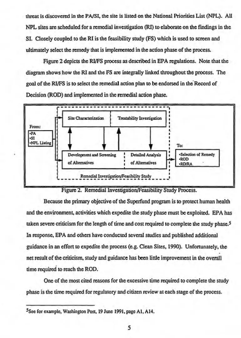
Figure 2 depicts the RI/FS process as described in EPA regulations. Note that the
diagram shows how the RI and the FS arc integrally linked throughout the process. The
goal of the RI/FS is to select the remedial action plan to be endorsed in the Record of
Decision (ROD) and implemented in the remedial action phase.
n
From:
>PA •SI
>NPL Listing
Site Characterization
I
Treatability Investigation
To:
Development and Screening
of Alternatives
Detailed Analysis
of Alternatives
•Selection of Remedy
•ROD
•RD/RA
Remedial Investigation/Feasibility Study
Figure 2. Remedial Investigation/Feasibility Study Process.
Because the primary objective of the Superfund program is to protect human health
and the environment, activities which expedite the study phase must be exploited. EPA has
taken severe criticism for the length of time and cost required to complete the study phase.^
In response, EPA and others have conducted several studies and published additional
guidance in an effort to expedite the process (e.g. Clean Sites, 1990). Unfortunately, the
net result of the criticism, study and guidance has been little improvement in the overall
time required to reach the ROD.
One of the most cited reasons for the excessive time required to complete the study
phase is the time required for regulatory and citizen review at each stage of the process.
The underlying problem with this issue has been understaffed agencies unable to meet
realistic review schedules. In order to alleviate this pressure, agencies are focusing on
providing adequate trained staff to perform the reviews in reasonable time. At present,
none of the players in Superfund is considering changing the time allowed for review.
Another commonly cited reason for the delay is the time required to adequately
investigate the site and document the nature and extent of contamination. This the heart of
the RI process. In order to expedite this phase, EPA recommends collecting and analyzing
a minimum number of samples at each stage of the study. Of course, identifying a
minimum number of samples is an artistic process rather than a scientific one. An iterative
process has been adapted fixjm geotechnical engineering and is now used by some
consulting firms (Myers, 1989). By collecting only the necessary data for each step in the
decision, this "observational approach" can avoid excessive time and cost for analytical data
collection.Another cumbersome process often cited as time consuming in the RI/FS process is
the screen and selection of the final remedy (Qean Sites, 1990). Because many potential
technological options may be applicable, each one must be considered in a cursory manner
during screening. While many environmental professionals have developed their own
rules-of-thumb to perform this exercise, no comprehensive EPA guidance on the subject
has been developed. Thus, the remedy selection process is conducted on a case-by-case
basis and rarely yields consistent results.
RAAS attempts to automate this screening process. By modeling the remediation
technologies in mass balance terms and describing the critical PS steps in decision logic,
RAAS develops a list of potentially applicable technologies from the broad range available.
Finally, the determination of the "applicable or relevant and appropriate
are determined. Section IV below will discuss the details of the ARARs identification
process and suggest ways that RAAS can capture its critical features.
Once a set of potential remediation alternatives is identified, the final step in the
feasibility study is the detailed analysis of the alternatives (see Figure 2). SARA provided a
detailed list of nine evaluation criteria to be used to compare the alternatives. Figure 3 lists
these nine criteria. Under the revised NCP, the detailed analysis of alternatives must
objectively discuss each of the alternatives based on each criteria The analysis is done to
determine the relative performance of each alternative and to identify the major trade-offs
among them (EPA, 1990c).
Overall Protection of Human Health and
Environment
Compliance with ARARs
Threshold Criteria
Long Term Effectiveness and
Pemianence
Reduction of Toxicity, Mobility and Volume tiirough Treatment
Short Term Effectiveness
Implementability
Balancing Criteria
Cost
State Acceptance Community Acceptance Modifying Criteria
Figure 3. Criteria for Detail Analysis of Alternatives.
The NCP distinguishes the detailed analysis of the alternatives from the final
No remedy failing the two threshold criteria may be considered in the final selection. The
balancing criteria arc used to trade off between the altematives and to determine the
alternative which is most "cost effective and utilizes permanent solutions and alternate
treatment technologies or resource recovery technologies to the maximum extent
practicable" (EPA, 1990c). Finally, comments from the state and community may be used
to modify the altemative selected or choose another alternative.
The cuknination of the study phase is the signing of the Record of Decision (ROD).
By signing the ROD, the site owner and the various regulatory agencies agree to implement
the selected remedy. With the ROD in place, the action phase can be implemented. While
the NCP provides the EPA a course of action to remediate a life threatening site prior to the
ROD (the removal action in 40 CFR 415), all sites selected for the NPL must be studied via
an RI/FS before a ROD is signed and the final remedial action is implemented.
This paper discusses RAAS as a method to expedite and standardize the study
phase of the CERCLA process. It should be noted that to date, EPA has signed over 700
RODS (EPA, 1991a). Thus, many sites now have activities underway in the action phase
(Figure 1) of the remediation process. A majority of theses sites are under design or
construction. Relatively few have operational clean-ups in progress. Because EPA has
only completed remediation at approximately 60 sites, emphasis is still required to provide
the means to cut the time required to select the remedy and sign the ROD. In the future, as
more of the sites move into the action phase, EPA will certainly be challenged to expedite
the action phase as well.
B. Expert System Software
1. Expert System Paradigm
Expert systems are "computer programs that perform sophisticated tasks once
thought possible only for human experts." (Benfer, 1991) Expert systems are
spreadsheets or statistical packages, by their use of programming methods such as
symbolic representation of knowledge and heuristic reasoning (Hushon, 1990; Benfer,
1991). Today, the term expert system defines a specific type of software that represents
the knowledge of an expert in a narrow domain and provides that knowledge to less
sophisticated users. These programs are also often called knowledge-based systems.
Expert systems are a product of artificial intelligence (AI) research. When
computers were first developed, some envisioned systems that would be able to reason like
the human mind. While AI research has continued with more realistic projects such as
speech and visual recognition, expert systems development spun off as its own field.
Expert system developers create practical applications using AI tools (Holtzman, 1989).
The first well-documented expert system was called MYCIN. The MYCIN system was
developed to aid doctors in identifying antibiotic therapies for infectious blood diseases.
MYCIN captures the diagnostic heuristics of doctors in a program which elicits conditions
about the patient and suggests potential remedies. Another early expert system, called
PROSPECTOR, assisted geophysicists in exploring for mineral deposits. Like MYCIN,
PROSPECTOR encoded the decision rules used by experts and allowed rapid, consistent
application of the rules in various settings.
Today , knowledge-based expert systems are ubiquitous. In a 1986 book.
Waterman identified 181 different systems (Waterman, 1986). Hushon found 69 systems
fielded or under development in the environmental field in a 1990 review (Hushon, 1990).
While environmental expert systems are relatively new, knowledge-based systems are
especially prevalent in the financial world doing everything from stock trading to screening
loan applications. With the development of more powerful computers, the term
knowledge-based system is evolving to include powerful systems which integrate visual
recognition and domain expert knowledge. As an example, researchers at Camegie-Mellon
have fielded a prototype autonomous vehicle which can "see" and interpret roadway signs
flipJW.W.
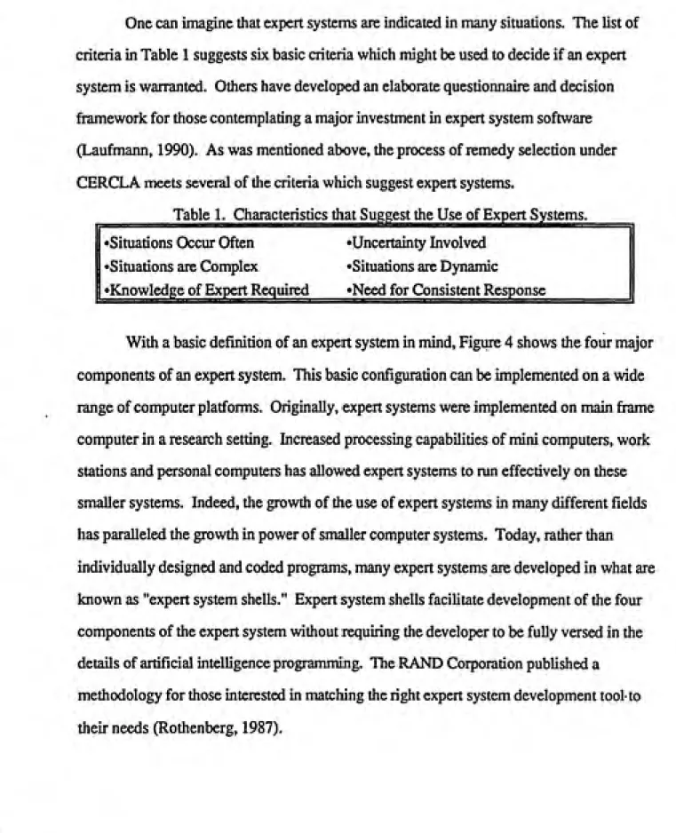
One can imagine that expert systems are indicated in many situations. The list of
criteria in Table 1 suggests six basic criteria which might be used to decide if an expert
system is warranted. Others have developed an elaborate questionnaire and decision
framework for those contemplating a major investment in expert system software
(Laufmann, 1990). As was mentioned above, the process of remedy selection under
CERCLA meets several of the criteria which suggest expert systems.
Table 1. Characteristics that Suggest the Use of Expert Systems.
Situations Occur Often 'Uncertainty Involved
Situations are Complex 'Situations are Dynamic
•Knowledge of Expert Required »Need for Consistent Response
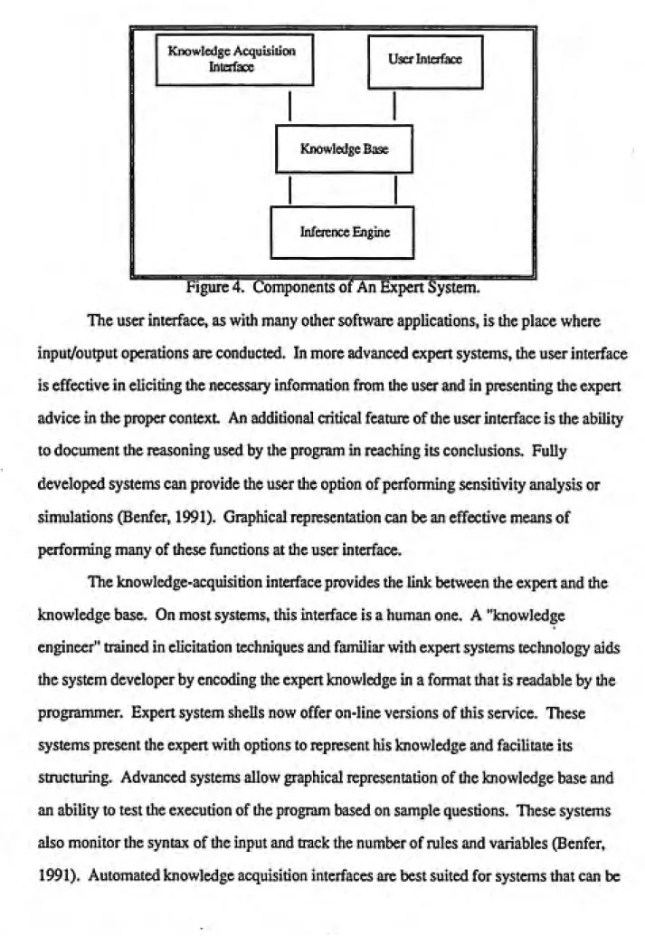
With a basic definition of an expert system in mind. Figure 4 shows the four major
components of an expert system. This basic configuration can be implemented on a wide
range of computer platforms. Originally, expert systems were implemented on main frame
computer in a research setting. Increased processing capabilities of mini computers, work
stations and personal computers has allowed expert systems to run effectively on these
smaller systems. Indeed, the growth of the use of expert systems in many different fields
has paralleled the growth in power of smaller computer systems. Today, rather than
individually designed and coded programs, many expert systems are developed in what are
known as "expert system shells." Expert system shells facilitate development of the four
components of the expert system without requiring the developer to be fully versed in the
details of artificial intelligence programming. The RAND Corporation published a
•
Knowledge Acquisition
Interface User Intoface
Knowledge Base
Inference Engine
Figure 4. Components of An Expert System.
The user interface, as with many other software applications, is the place where
input/output operations are conducted. In more advanced expert systems, the user interface
is effective in eliciting the necessary information from the user and in presenting the expert
advice in the proper context An additional critical feature of the user interface is the ability
to document the reasoning used by the program in reaching its conclusions. Fully
developed systems can provide the user the option of performing sensitivity analysis or
simulations (Benfer, 1991). Graphical representation can be an effective means of
performing many of these functions at the user interface.
The knowledge-acquisition interface provides the link between the expert and the
knowledge base. On most systems, this interface is a human one. A "knowledge
engineer" trained in eUcitation techniques and familiar with expert systems technology aids
the system developer by encoding the expert knowledge in a format that is readable by the
programmer. Expert system shells now offer on-line versions of this service. These
systems present the expert with options to represent his knowledge and facilitate its
structuring. Advanced systems allow graphical representation of the knowledge base and
an ability to test the execution of the program based on sample questions. These systems
also monitor the syntax of the input and track the number of rules and variables (Benfer,
fully expressed in terms of a deductive reasoning "if-then" format. Systems that integrate
numerical functions will require programming efforts beyond the scope of the shell.
The heart of the expert system is the knowledge base and the inference engine. The
knowledge base is like other databases in that it stores information about a specific domain.
In addition, the knowledge base represents domain information with if-then rules and other
methods such as "frames." Frames represent associations among concepts as nodes with
arcs between them (Hushon, 1990). These deductive and symbolic structures allow for a
much richer representation of the problem. The knowledge base can represent more than a
static database because of its link to the inference engine. Through inference, implicit
conclusions can be drawn that extend the database beyond its structured representation of
information.
The inference engine provides the mechanism to query the knowledge base and
develop additional conclusions. It provides a means of interpreting the symbolisms in the
knowledge base and deducing unstated results. Often the reasoning utilizes mathematical
formulas to develop additional information from the input data and infer subsequent results.
In addition, inference engines can accommodate the concepts of probability or
rules-of-thumb to capture the subjective nature of many decisions. The inference engine is most
directly linked to the field of artificial intelligence and to formal studies of reasoning.
The development of expert system environments has exploded in the last five years.
With this growth of software and consultants, those wishing to employ expert systems no
longer need the computer programming skills necessary to construct a system from scratch.
The flood of tools and salesmen however, does necessitate that new users understand the
applicability, strengths and weaknesses of expert systems.
2. Expert System Advantages and Disadvantages
The advantages attributed to expert systems follow logically from the characteristics
listed in Table 1 which indicate situations when an expert system might be warranted.
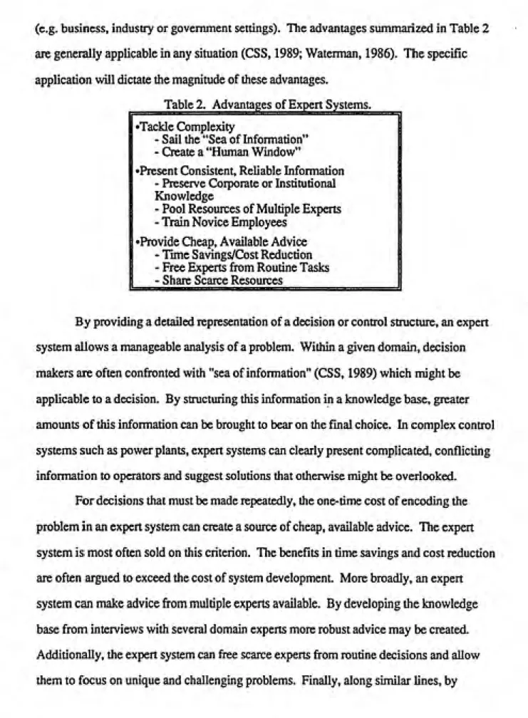
(e.g. business, industry or government settings). The advantages summarized in Table 2
are generally applicable in any situation (CSS, 1989; Waterman, 1986). The specific
application will dictate the magnitude of these advantages.
Table 2. Advantages of Expert Systems.
F
Tackle ComplexitySail the "Sea of Information" - Create a "Human Window"
•Present Consistent, Reliable Information
- Preserve Corporate or Institutional
Knowledge
- Pool Resources of Multiple Experts - Train Novice Employees
•Provide Cheap, Available Advice - Time Savings/Cost Reduction - Free Experts from Routine Tasks - Share Scarce Resources
"H
By providing a detailed representation of a decision or control structure, an expert
system allows a manageable analysis of a problem. Within a given domain, decision
makers are often confronted with "sea of information" (CSS, 1989) which might be
applicable to a decision. By structuring this information in a knowledge base, greater
amounts of this information can be brought to bear on the final choice. In complex control
systems such as power plants, expert systems can clearly present complicated, conflicting
information to operators and suggest solutions that otherwise might be overlooked.
For decisions that must be made repeatedly, the one-time cost of encoding the
problem in an expert system can create a source of cheap, available advice. The expert
system is most often sold on this criterion. The benefits in time savings and cost reduction
are often argued to exceed the cost of system development. More broadly, an expert
system can make advice from multiple experts available. By developing the knowledge
implementing the expert system on multiple workstations, an operation can effectively
share limited expert resources.
Well designed and programmed expert systems present consistent and reliable
information to users. Expert systems can provide managers some consistency between
field personnel. By approaching each problem from the same broad perspective, the
resultant decision is likely to be grounded on similar principles. In addition, a
well-documented expert system can provide an excellent training tool. Users can input a variety
of circumstances and learn the process followed by the system. Most expert systems create
reports that also foster consistency and leaming. The expert system is not likely to fall pray
to illness or absent-mindedness which adversely affect human experts. Lasdy, they can
preserve corporate or scientific knowledge which might be lost when the expert retires.
Benfer calls expert systems "inherently cumulative." (VanHom, 1986; Benfer, 1991)
An understanding of the disadvantages of expert systems is more important for new
users of experts systems. Otherwise, considerable time and expense can be invested in
unwarranted software which is rarely used. Table 3 notes some of the often cited problems
of expert systems. Some of the disadvantages are simply the opposite of the advantages
listed in Table 2. These problems are likely to be found in poorly planned systems which
were not adequately justified.
__________Table 3. Problems with Expert Systems.______^^
•Provide Wrong Answers 'Contain Hidden Rules
•Use Too Many Assumptions »Advice Interpreted Incorrectly
incorrect information. First, the knowledge base may itself be wrong, either by factual or structural means. If the knowledge is correct, problems may still arise because of faulty rules, improper interpretation of synonyms supplied by the user or an inabiUty to interpret complex input (CSS, 1989). Finally, the knowledge base may have been created from interviews with poorly qualified "experts" or developed by untrained "knowledge
engineers." (Van Horn, 1986)
Hidden rules represent another serious concern for expert system users. Hidden
rules can be described as rules that discriminate between different answers in ways that are unknown to the user. An excellent example which demonstrates the impact of a hidden rule might be found in an expert system which screens loan applications. The mle might state:
If the subjects address is in Chicago,
And the subject's age is less than 25, And the subject is non-caucasian.
Then die credit rating is poor. (CSS, 1989)
In this rule, if the non-caucasian statement is not clearly documented, it discriminates in subde but powerful way. More disconcerting examples might arise when results of linking several of these nested if statements yields the discriminatory information. These types of rules could easily be extended to bias against treatinent methods or technological choices in
other applications.
When the knowledge base encodes extensive assumptions, the expert system output
can also be problematic. By chaining together an extended Ust of assumptions, the system
can generate absurd or potentially dangerous advice. These assumptions can also be harmful when they encode values that are not universally accepted in the community of users. Medical recommendations that violate a users reUgious or ethical beUefs may be technically correct but will ahenate the user (CSS, 1989).
users are inclined to be very trusting of computer output. In both time-critical and highly
technical fields, this blind faith in a system can have catastrophic results. The aphorism "a
little knowledge can be a dangerous thing..." apdy encompasses the concern of many
expert system critics (CSS, 1989).In an article examining research directions for expert systems, Wesley captures both
the potential advantages and disadvantages of expen systems with the "equation"
(Wensley, 1989).
Expert System + Novice = Expert
This "equation" clearly shows the advantages of availability and ease of use attributed to
expert systems. Closer inspection, however, points to the pitfalls of ready acceptance of
this expression. The novice must both provide the right input to the system and accurately
interpret the results. Systems that claim these issues are not a concern almost assuredly are
not warranted except perhaps as training tools or as archives of knowledge.
3. Issues in Expert System Development
Proper protocol for developing expert system is widely documented (Benfer, 1991;
Waterman, 1986). Originally, expert systems were developed along the lines of traditional
software development ("life-cycle development") which involves extensive documentation
and analysis prior to any actual programming. As shells have become available, the expert
system development process has evolved as a different form of programming. This
process, called rapid prototyping, involves first developing a basic version of the program
which shows how the final system might look and act but has a very simple knowledge
base and inference structure (Waterman, 1986). With the help of the expert and the
knowledge engineer, the knowledge base is then expanded. This process mirrors the
human learning process and allows the representation of the decision to grow with the
capabilities of the system. This process continues until the system reflects the skill of the
human expert. Four key issues which must be addressed in this development process are
Knowledge Acquisition. A well defined strategy for knowledge acquisition is
essential for a complete representation of the problem and a fully operational software tool.
Techniques of elicitation useful in traditional decision analysis (Holtzman, 1989) and social
science research (Benfer, 1991) are commonly prescribed for knowledge acquisition. The
determination must be made whether one or several experts will be consulted and how
differences in their opinions wiU be reconciled. Another critical decision is whether to use
experts frx)m "inside" or "outside" a field of expertise or both. The necessary methodology
for acquisition may drive the choice of the shell used for the program (Rothenberg, 1987).
Knowledge Representation. As was mentioned briefly above, different
formalisms arc available to represent the knowledge base (e.g. trees or "frames"). Trees
are favored in systems which consider a single issue at a time whereas frames are useful
where multiple combinations of information must be considered simultaneously
(Benfer, 1991). More broadly, a work notes "it may be that the act of representing
knowledge and inference as expUcit rules will help to uncover assumptions and bias in the
minds of those on whom the program is modeled." (CSS, 1989) Knowledge
representation must be a central focus in the early stages of program development. The
more robust the structure, the more likely the program will evolve and remain useful as the
domain of expertise expands.
A final issue concerning knowledge representation is the need to expUcitiy
acknowledge that political, social and epistemological viewpoints are critical in most
decisions.(Kjaergaard, 1989). Without an analysis of the stakeholders in the decision, the
system may be discredited by those who are damaged by its recommendations. Theseissues are often so fundamentally held by domain experts that careful use of independent
observers may be necessary to avoid these pitfalls (Benfer, 1991). The setting in which the
system will be used, either public or private, also affects the representation of knowledge.
The pubUc sector has political, economic and environmental factors unique to it which can
Verification and Validation. The process of validating expert system software
is difficult because of the system's ability to draw conclusions beyond the explicitly stated
data. Thus, systematic validation is difficult (Benfer,1991). Because validation is such a
critical issue. Section VI of the paper is devoted to this issue.
Handling Uncertainty. Uncertainty management is the heart of an effective
expert system. In order to capture the knowledge and skill of a human expert, the software
must account for the human ability to consider the likelihood of events based on evidence that itself is inherently uncertain. Table 4 lists both the typical causes of uncertainty
encountered in expert systems and theoretical and pragmatic methodologies employed to
address uncertainty. It serves as an outline for the following discussion of uncertainty
management
Table 4. Uncertainty Management. Sources of Uncertainty
- Unreliable Information/Data - Imprecise Descriptive
Language
- Inference with Incomplete - Poor Integration of
Information Knowledge from Multiple
______________Experts_______________
Methods of Uncertainty Management
•Complete Theories 'Expert System Techniques Probability Theory - Certainty Factors
Demster-Shafer TTieory - Subjective Bayesian Method
Possibility Theory______________- Theory of Endorsement
Fundamental uncertainty stems fh)m two sources: unreliable data and uncertain
knowledge (CSS, 1989). Data collected from observation or instrumentation that are used
as input to an expert system can be wrong, contaminated or incomplete. This inherent
uncertainty forces the user to understand its source and provide the expert system a way of
incorporating measurable variability in the data. Understanding the weaknesses of
human expert in an area where concepts are poorly defined, the resultant advice must be qualified by this underlying lack understanding.
A second source of uncertainty can be attributed to the imprecision with which our language is able to represent complex ideas. Expert systems often attempt to accommodate input in "natural language." Thus, a broad range of synonyms and viewpoints must be contained in the database. When the system is forced to proceed based on a tenuous or erroneous assumption about the input, the resultant advice will be similarly affected.
Beyond imprecision in language, operational expert systems must function with data that does not match any definition in the database. These incomplete problem definitions add further imprecision to the information on which an expert system will ultimately make a recommendation. These vacancies can occur both in the data and in the representation of the problem.
Finally, in systems which acquire knowledge from multiple experts who disagree, the representation of this disagreement leads to unreliable output. In order to press forward, system developers represent a "consensus" viewpoint which results in often subtle biases (Ng, 1990) This representation ignores the even more subde issue of the
relative level of expertise among domain experts.
Formal representations of uncertainty are fundamental to science and mathematics. They were developed long before the advent of computers or expert systems. Table 4 indicates three different theoretical models used to represent uncertainty. Each was developed to serve a particular aspect of uncertainty management When applied in expert systems, each serves to combine uncertain existing knowledge and predict uncertain future events. Ng and Abramson call this process "belief propagation." (Ng, 1990)
known probability of being true. Observing the assumptions of mutually exclusive and exhaustive hypotheses, Bayes' Theorem can be used to combine available information to decrease the uncertainty of a hypothesis. Of course, the underlying premise necessary to apply probability theory is that aU of the necessary conditional probabilities can be
determined—no small task. Often, the assumption of the independence of the probabilities of separate pieces of evidence for a given hypothesis is made in order to limit the number of
conditional probabilities that must be determined. Even with these additional
simplifications, a significant information gathering burden remains.
Dempster-Shafer theory is motivated by the difficulty in probability theory in expressing ignorance. The theory is both mathematically and symbolically complex and has not been implemented in operational expert systems.
Possibility theory, which is based on the concept of fuzzy sets, has been
implemented. Possibility theory replaces the binary logic in probability theory with system that allows "shades of gray" to be expressed. Membership in a fuzzy set is not bound to
the yes or no criteria of probability theory sets. In addition, there is no restriction on the sum of the possibilities of an outcome. In probability theory, the sum of the probabilities of an outcome must equal 1. Fuzzy logic allows a range of logic properties and allows belief propagation to be formally expressed and coded. Those who question the utility of
possibility theory note that because a possibility set is defined subjectively, no additional
accuracy is introduced into the definition. Due to its potential, fuzzy set theory is an area of
extensive research (Ng, 1990).
Because of the difficulty in fully implementing probabiUty theory and the complexity of the other theoretical approaches mentioned above, several less
Certainty factors were developed in conjunction with MYCIN because the developers felt that inadequate medical information would be available to allow
implementation of probability theory. Certainty factors are the most commonly used method of uncertainty management in expert systems fielded today. A certainty factor can range between -1 and +1 with -1 representing a bit of evidence confirming that a hypothesis
is false and +1 representing evidence confirming that a hypothesis is true. Formal rules for
combining certainty factors have been developed and implemented in software. The key assumption in the use of certainty factors is the assumption that all hypotheses are mutually independent. Because of the weakness in this assumption, theoreticians continue to narrow the range of applicability of certainty factors.
The subjective Bayesian method relies on the concept of likelihood ratios. The likelihood ratio is defined as ratio of the probability that the evidence is true given that the hypothesis is true (p(EIH)) to the probability that the evidence is true given that the
hypothesis is false (p(EIH)) which can be thought of as the odds that p(E!H) is true. This
method has several key assumptions such as conditional independence of evidence under both a hypothesis and its negation. These demands are rarely met and systems that
overlook these restrictions have been shown to perform poorly.
Endorsement theory attempts to represent the reasons for believing a hypothesis.
This qualitative theory is beyond the scope of this report but is mentioned here for completeness (Ng, 1990).
The preceding discussion of uncertainty management is based on an understanding of probability theory and was derived from sources who endorse probability theory as the most rigorous approach to uncertainty management. Unfortunately, probability theory is impossible to implement fully. Thus, users of expert systems must look at the simpler models for uncertainty management and understand their inherent assumptions prior to
Because the uncertainty in a complex decision structure is multi-faceted and
ubiquitous, no model can claim to represent it all. The uncertainty management issue must
be an explicit component of the basic design of an expert system and must constantly be reviewed and documented throughout testing and implementation.
4. Beyond Expert Systems
No single method has been proposed for representing and programming expert
systems for decision support. In fact, the growing availability of expert system shells is causing the number of development tools to proliferate. In an interesting attempt to provide
a unifying paradigm, Holtzman proposed an expert system based on the formal concepts of decision analysis (Holtzman, 1989).
Holtzman focuses on the importance of the distinction between the decision maker
and the decision analyst He expresses concern that in current expert system application, this distinction is confused and blurred. When in the system development, the domain experts assume the role of the decision maker, they impart their preferences and
information on the decision maker in very subtle ways. They may not ask the sort of basic
questions that help to create an accurate, flexible representation of the decision structure.
To combat this bias, Holtzman recommends a decision analysis approach to
problem formulation. He suggests the use of influence diagrams to formally outline all
aspects of the decision problem. Through this rigorous analysis, the problem can be structured to explicitly recognize the decision maker's attitudes toward risk and preferences. With the formal structure laid out in an influence diagram, the required subjective probability infonnation can be elicited from either domain experts or the decision maker and integrated into the influence diagram. The resultant assemblage can then be queried to determine the appropriate recommendation for action. In his book, Holtzman
diagrams the set of computer based programs that must be associated to fully automate the process he advocates. He bolsters his position by describing a medical diagnosis system
Holtzman suggests three main advantages of his "intelligent decision systems" over
traditional expert systems. First, he states that the intelligent decision system, because of
its clearly defined decision stmcture, is more effective in focusing the knowledge
acquisition process. Second, because uncertainty is explicitiy confronted using decision
analysis methodology, the knowledge representation and uncertainty management schemes
are more effective. And third, because his model specifically acknowledges preferences in the decision framework, it has a greater normative power. In other words, an intelligent
decision system can more effectively determine which alternative among those considered
is better. He argues that the decision analysis methods used to define the preferences and
circumstances of a particular decision augment the domain expertise of a additional expert
system and create a more powerful tool.
Of course, as was discussed above, the use of formal probability concepts comes at
a significant cost. Tools of eUcitation must be employed to objectively determine decision
maker preferences and probability distributions associated with the knowledge base.
Numerous conditional probability statements must be elicited to ensure that the chance
nodes in the influence diagram are properly described.
The methodology presented by Holtzman is certainly not appropriate for all expert
system applications. It does, however, offer a rigorous scheme which can be employed in
high risk situations where fuU representation of all aspects of the decision are important.
Because it provides a formal treatment of probability and it attempts to explicitiy state the
portions of the decision which are influenced by decision maker preferences, it has the
potential to be withstand a more thorough validation.Having introduced CERCLA and the concepts of expert systems, the following
section describes the Remedial Action Assessment System (RAAS). The discussion ties
C. RAAS
1. Objective
Broadly, the objective of RAAS is to automate the CERCLA FS process. To
achieve this goal, RAAS will ultimately be integrated with other expert systems (see
discussion below). More specifically, RAAS's first objective is to automate the technology
screening phase of the FS process. Referring to Figure 2, RAAS wiU provide the
development and screening of alternatives based on a site characterization. The RAAS
output will focus and facilitate the detailed analysis of alternatives. Successful use of
RAAS should expedite signing of the Record of Decision and start of remedial action at the
site.
In its initial phase, RAAS wiQ provide the user a list of potential "treatment trains"
for a contaminated hazardous waste site. A "treatment train" is defined as a set of unitremediation processes arranged is such a way that their implementation will lead to
complete site clean up (e.g. a treatment train for a groundwater remediation might consist of
a pump-and-treat treatment technology train). RAAS first identifies technologies that will
effectively mitigate site risks and then arranges them in a sequence that will meet the overall
objectives for site cleanup. Both the individual technologies and the resultant process are
evaluated to ensure that they are viable with respect to basic technological constraints. In
itscurrentphase, RAAS will provide a comprehensive list of potential trains. All
reasonable sets of alternatives will be submitted to the user for further review. Subsequent
versions will include more discriminatory criteria that will allow a ranking of the potential
alternatives.The first phase of RAAS has several potential benefits. Several of the benefits are
commonly attributed to expert systems. They include: decreasing the time and cost
required to be considered under SARA but are unfamiliar to most practicing environmental
professionals. Finally, RAAS provides a consistent vehicle for performing the screening.
Once the regulatory community accepts the method used by RAAS, it may facilitate the
acceptance of remedial action plans.
RAAS is not the first attempt to use a computer based expert system to automate
remedy selection in the RI/FS process. Two other systems are documented in the literature
(Hushon,1990). The Cost of Remedial Action (CORA) model was developed by EPA and
CH2M Hill primarily to assist the EPA in developing order of magnitude cost estimates for
site cleanups. The output of the model is used to better budget for future Superfund
expenditures. In order to budget for a clean up however, the developers found it necessary
to at least guess at what type of technology would be employed a the site. Thus, as a front
end to the cost estimating model, they built the "Technology Screening System."(Chenu,
1990) A similar system was developed by Roy F Weston and EPA (Hushon, 1990). The
"Technology Selection of Altemative Remedies" (TSAR) was a prototype system which
identified potential technologies and recommended additional input information that must be
collected from field studies to verify the potential of the technology in the feasibility
stiidy.(Greathouse, 1989; Hushon, 1987)
Both CORA and TSAR used the traditional expert system approach to suggest
remediation technologies. Their knowledge bases have IF...THEN... statements that
suggest remediation technologies based on user answers to questions. In CORA, tiie
questions are primarily true/false statements about the contamination and the site. The level
and extent of contamination are not well qualified in the input. As a result, the output of the
technology screening phase of CORA is very general and of limited value beyond scoping
cost estimates. TSAR also focuses at the level of individual technologies and is primarily
useful in identifying necessary field and laboratory investigations. While both systems are
effective for their narrowly defined functions, they help to highlight the need for RAAS and
As will be detailed below, the particular innovation most significant in the first
phase of RAAS is its ability to model the effectiveness of remediation technologies. By
representing each remediation technology as a unit process and describing its effect on the
contaminant and media in a mass balance model, RAAS expands the potential site
conditions which can be evaluated beyond those of the rule-based schemes in CORA and
TSAR. RAAS can consider more technologies, more contaminants and a wider range
contaminant matrix than the other models. By modeling the physical processes of
remediation in addition to the procedural aspects of the CERCLA process, a more realistic
simulation of the actual decision process is achieved.
2. Implementation Approach
This section describes the basic method RAAS uses to reach its objective. It relates
the workings of the software in a graphic manner and explains the nature of the user
interface. Depiction of an example "run" wiU help to reinforce these descriptions.
RAAS is developed using the object-oriented software development model (Bohn,
1991) In object-oriented programming, a decision problem is described in units that are
natural to the process (i.e. as objects). Each object has an identity described with data or
equations. The entire problem is thus defined as a set of objects that are linked together.
By passing messages among the objects, the program can represent the decision process as
time progresses. The critical concepts which make object-oriented analysis effective in
describing the remedy selection process are that objects may be arranged hierarchically and
inherit information from their parent object. In addition, specific instances of an object can
be created during program execution to depict the results of different processes (e.g.
instances that show the effects of different clean up technologies on a given waste matrix).
Objects allow modularity in development and facilitate integration of knowledge from
separate experts to emulate the real process~the CERCLA FS process.
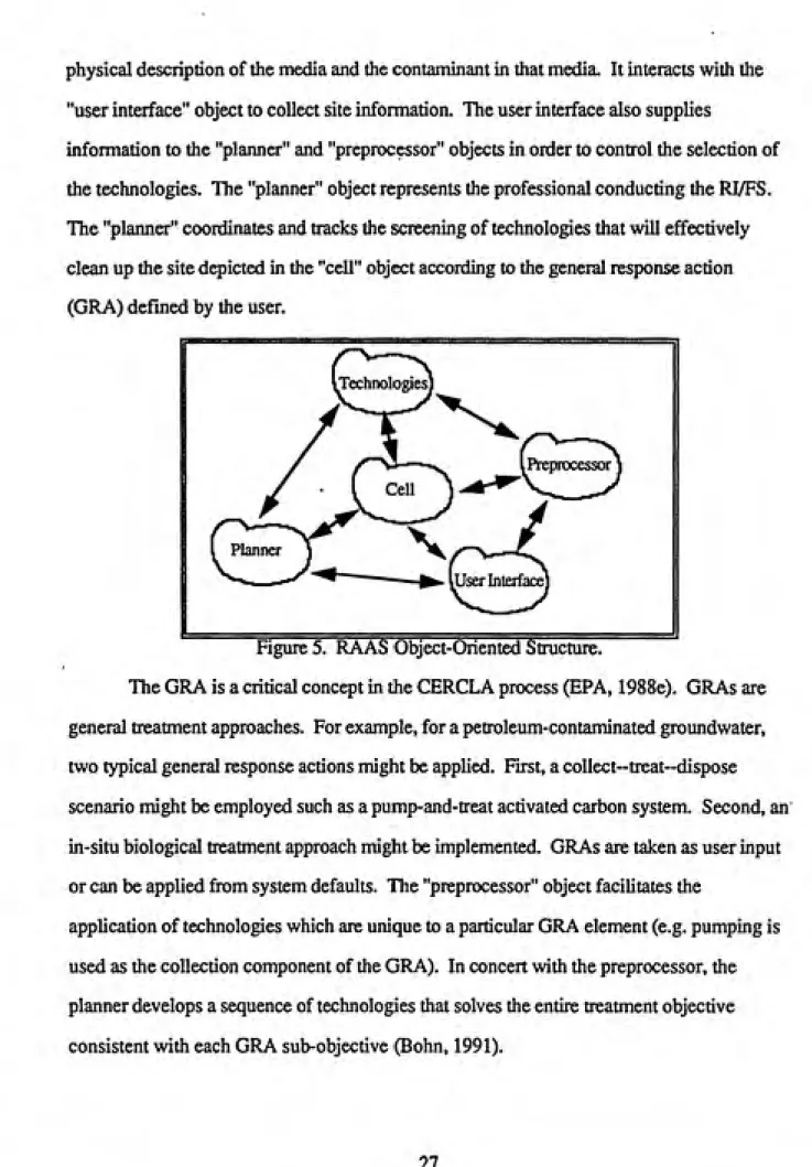
physical description of the media and the contaminant in that media. It interacts with the
"user interface" object to collect site information. The user interface also supplies
information to the "planner" and "preprocessor" objects in order to control the selection of
the technologies. The "planner" object represents the professional conducting the RI/FS.
The "planner" coordinates and tracks the screening of technologies that will effectively
clean up the site depicted in the "cell" object according to the general response action
(GRA) defined by the user.
Technologies
( Planner J^ X.
User Interface
I Pteiwocessor \
Figure 5. RAAS Object-Oriented Structure.
The GRA is a critical concept in the CERCLA process (EPA, 1988e). GRAs are
general treatment approaches. For example, for a petroleum-contaminated groundwater,
two typical general response actions might be applied. First, a collect-treat-dispose
scenario might be employed such as a pump-and-treat activated carbon system. Second, an
in-situ biological treatment approach might be implemented. GRAs are taken as user input
or can be applied from system defaults. The "preprocessor" object facilitates the
application of technologies which are unique to a particular GRA element (e.g. pumping is
used as the collection component of the GRA). In concert with the preprocessor, the
planner develops a sequence of technologies that solves the entire ti^atment objective
The heart of the technology screening phase of RAAS is the "technology" object.
Once the planner has an accurate representation of the existing conditions and has the user's
objectives for clean up in the form of a GRA, it systematically queries technologies to
develop viable treatment trains. The RAAS methodology uses two distinct processes to
accomplish this task (Pennock, 1991).
The first task is to determine the applicability of a particular technology. This is
shown in Figure 6 (Pennock, 1991). The technology object, which contains a series of
enabling and disabling conditions, is queried relative to the site conditions. Second, the
regulatory object is queried to determine if the technology is applicable in the given site
conditions. The inference object facilitates this rule-based analysis by accepting
knowledge, performing the inference and passing back the answer to the question. The net
result of this sub-system is to determine in a qualitative manner if a technology is
applicable.
h
Regulatory Object
Inference
Object
Technology Object
IL
Figure 6. RAAS QuaUtative Evaluation for Applicability
The second task is to determine the effectiveness of a given technology in meeting
the clean up objective. Each technology is represented by a set of mass balance equations
which model before and after conditions at the site when a technology is applied (see
section III below). The model of each technology is a coarse numerical approximation
which facilitates screening. Figure 7 shows how the technology object interacts with other
objects to screen for effectiveness (Pennock, 1991). The contaminant, medium and
physical properties which might be encountered in a treatment process. The site object is a
temporary instance of the cell object which shows how the site is altered after one or a
series of technologies has been appUed. The site object tracks all of the critical parameters
so that the "planner" can determine if the technology is effective.
Medium
Object
Contaminant
Object
Reaction
Object Technology
Figure 7. RAAS Qualitative Evaluation for Effectiveness.
As an example of the RAAS methodology, consider again the
petroleum-contaminated soil. In the initial interaction with the user, the system would query for the
principle contaminants (e.g. benzene or toluene) and the concentration of these
contaminants based on field tests. Additional physical parameters such as soil type and
hydraulic conductivity would also be elicited from the user. Next the GRA would be
determined. For simplicity, assume that the user required that an in-situ bioremediation
scenario be implemented.(I)nject
(Dreat
/\eiobi\
AnaerobK
I-l
1-2
Injection Technology
List
Subobjective
T- 1 T-2
T-3
Treatment
Technolgy
List
Final Objective
I I = Feasible Technology ^^ = Infeasible Technology
(I-l)-(T-l)-(T-3) a-l)-(T-2)-(T-5) (I-l)-(T-2)-(T-6)
= Potential Treatment Trains
I
Figure 8. RAAS Technology Screening Process.
Consider the bioremediation technology screening. First assume that two potential
technologies are available: aerobic and anaerobic bioremediation. When the planner
invoked the aerobic treatment, the applicability determination would be made first. Then if
found applicable, the technology object would run the mass balance model for aerobic
bioremediation and compare the residuals to the constraints of the program and those
supplied by the user. If found effective, the planner would link the technology with a
successful injection technology to create a complete treatment train. The resultant treatment
train and any others that are screened as both applicable and effective would be submitted to
the user for further evaluation. Figure 8 shows a result which includes three potential
treatment trains. Each uses the same injection technique but two use aerobic and one uses
anaerobic biodegradation. The user could then interact with RAAS to examine the decision
3. RAAS as an Expert System
Strengths. RAAS clearly employs the four basic components of an expert system
shown in Figure 4. The user interface communicates through interactive screens which
elicit site data and a GRA from the user and retum potential treatment trains and supporting
information. The inference engine is utilized by the technology objects to evaluate for
applicability and by the planner to determine the overall effectiveness of a potential
treatment train. Knowledge acquisition is accomplished by augmenting several of the
different objects which contain data. This distribution of the knowledge base is one of the
primary justifications for the object-oriented programming method used.
The critical programmatic innovation in RAAS is the distribution of the inferencing
and numerical calculations among the different technology objects (Pennock, 1991). This
distribution will allow incorporation of additional objects which allow RAAS to further
emulate the FS process. It will also facilitate RAAS's interaction with other software
systems which might provide unique input to the model of the FS process.
Weaknesses. The current version of RAAS also possesses several weaknesses.
They include: knowledge representation and uncertainty management. These weaknesses
will be addressed in subsequent versions of the program but deserve mention here so that
future work is focused on them.
While RAAS's object-oriented framework for alternative screening is functional,
the framework for a RAAS method which performs a detailed analysis of alternatives is not
clearly defined. The realm in which the final remedy selection is made is highly political
and an adequate representation of this process will be elusive (Kjaergaard, 1989). In
addition, RAAS plans to integrate with three other systems which will provide data on cost,
risk and regulatory compliance essential for the ultimate remedy selection.
structure to allow passing parameters to and from MEPAS must be designed to integrate
risk-related information at the appropriate steps in RAAS execution. The Remedial Action
Cost Estimating Routine (RACER) system^, under development by the Air Force, will
provide detailed, site-specific cost estimates for remedial actions. As with MEPAS the
RACER program must be queried at the appropriate times and with the appropriate
parameters to emulate advanced screening and the detailed analysis of the altematives. The
ARARs ASSIST system, which will provide detailed information on ARARs compUance,
is discussed in section IV below. Other systems, yet undeveloped, may be required to give RAAS sufficient capability to accurately screen the treatment trains and then analyze the
best ones based on the nine criteria set out in CERCLA section 121 by SARA and codified
in the NCR See Table 3 above.
RAAS must also further address the issue of uncertainty management Under the
first phase, the program does not provide the capability to represent the variability in either
the site data or the output of the numerical mass balance models of the remediation
technologies. While these shortfalls are not fatal to RAAS's first phase objective of
providing a list of potential treatment technologies, in order for future versions of RAAS to
have credibility differentiating between proposed treatment technology train,s uncertainty
management must be carefully implemented in the program. 4. Summary/Need for Further Development
RAAS can be seen to have two objectives. The first, technology screening, will be
operational with the first phase of the software. The second, advanced screening and
remedy selection, can only be achieved in subsequent versions. As was previously stated,
the objectives of this paper are to assist with the implementation of phase one of RAAS and
to provide information which will help to focus the work in subsequent phases.
^The RACER program is being developed by the U.S. Air Force Civil Engineering SuRwrt Agency at
The next three sections of this paper address issues important to the completion of
the screening phase of RAAS. They include: development of additional technology modules; integration of the ARARs screening process; and the expansion of RAAS's screening capabilities to include screening based on effectiveness, implementability and cost In Section VI, a method to validate phase one will be discussed. The paper
pi. Technology Modules
A. General
The technology module is the critical component in RAAS's method for screening technologies for applicability and effectiveness at a hazardous waste site. As was described above and diagrammed in Figures 5-7, the technology object contains a two-part
representation of each clean up technology. The first part is a set of inference rules which compare the constraints of the technology to the conditions at the site. The second is a
mass balance model which is invoked to determine what residual waste streams would result if the technology was applied at the site. If a technology passes both the test for applicability and the test for effectiveness, it is incorporated into a treatment train recommendation.
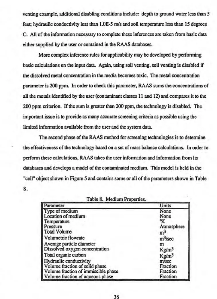
At present, RAAS contains modules for approximately 95 different remediation technologies. These technology modules describe the basic process (e.g. catalytic oxidation describes all types of incineration) but do not describe specific technology options for that process (rotary kiln, Uquid injection). Alternative options are called "process options" in RAAS. This section of the paper describes the information necessary to include a new process option in RAAS. Following this introduction, details of three process options will be presented.
In evaluating the applicability of a remediation technology, RAAS focuses on basic parameters about the medium, the contaminants and the site conditions. Theses parameters are supplied by the system user in the initial session with RAAS. RAAS works with the 10 medium types shown in Table 5 and contains information on 399 contaminants divided into the 14 categories shown in Table 6. For each of the contaminants, the RAAS database